
Blender 3D: Noob to Pro/Procedural Eyeball in Cycles
Knowing before Making
[edit | edit source]Blender is a powerful and complex 3D modeling and rendering package. However, before you can make anything, you need to understand several concepts used in 3D modelling and related fields. Examples include:
- Understanding the process of 3D modeling and rendering
- Understanding how the axis and 3D coordinates work in Blender.
- Understanding orthographic and perspective views.
- Local coordinates, parent objects, and child objects.
- Blender's user interface and how to navigate it.
- Viewing a scene from different camera angles
Don't be scared by their long names; a lot of these are actually pretty intuitive and easy to grasp. Of course, since you're not doing any actual modelling in this unit, you might be tempted to skip ahead, and that's completely fine! Just know that understanding these concepts well will help you a lot in the long run, and proceeding through tutorials in order will build a strong foundation for you to build on. Prior knowledge also plays a huge part in this, so if you're coming from other 3D software, you should already be familiar with these concepts.
That said, the actual fun (making stuff in Blender) comes in the next unit. However, keep in mind that Blender is not the kind of software you can jump into and experiment with. It's notorious for having a steep learning curve. It's less like exploring an unfamiliar city and more like flying a spaceship; if you hop into the pilot's seat without knowing the fundamentals, it's going to be near impossible to get off the ground.
Blender-specific terminology
[edit | edit source]Like any subject, 3D graphics has its own words and terminology used to describe specific ideas. In this book, important words are highlighted and defined on their first use. If you've missed or forgotten the meaning of a word, try looking it up in the Glossary.
Things you'll need
[edit | edit source]In order to follow the tutorials, you need a computer with Blender installed. You can download the latest Blender release here.
Depending on your system, you may also need the appropriate Python installation. Each version of Blender requires a specific version of Python, but it's usually packaged with Blender.
The Blender team has the Blender Long Term Support program which provides a stable Blender version with 2 years of support. During the 2 year support window, no new features, UI changes, API changes or other enhancements will be done; only critical fixes will be applied. This allows teams working on long-lasting blender projects to use a single supported version over a 2 year period. Long term versions are indicated below with the LTS suffix and a year indicating the last year of support.
| Blender version | Python version |
|---|---|
| 2.79 | 3.5 |
| 2.83 LTS 2022 | 3.7 |
| 2.90 | 3.7 |
| 2.93 LTS 2023 | 3.9 |
| 3.0 | 3.9 |
| 3.1 | 3.10 |
| 3.3 LTS 2024 | 3.10 |
| 3.4 | 3.10 |
| 3.5 | 3.10 |
| 3.6 LTS 2025 | 3.10 |
| 4.0 | 3.10 |
| 4.1 | 3.11 |
You can check Python version on Scripting workspace using:
import sys
print(sys.version)
Since Blender is open-source software, you can download the source code and build it yourself, but it's easier to download a pre-built binary. As of Blender 4.0, compiled releases are provided for the following operating systems:
- Windows 8.1, 10, and 11
- macOS 11.2 Intel or Apple Silicon
- Linux with glibc 2.28 or newer
Along with the website, many Linux distributions have Blender available in their package repositories, though it may be a slightly older version. You can use your system's package manager to download and install the package. It's also available on steam.
Windows users can also choose between an executable installer ("setup wizard") and a ZIP archive.
After the installation process is finished, Blender should appear in the Graphics section of your desktop environment application menu.
You may also want to download a 2D image editor, such as GIMP, Paint.NET, or Photoshop or a media player, such as VLC.
It's a good idea to have pencil and paper handy for sketching and taking notes. There's a lot to absorb. Taking notes as you go will pay dividends later.
Where to Go for Help
[edit | edit source]If you get stuck, you can ask for help from other Blender users in the appendices.
Additional Resources
[edit | edit source]Many modules have a section like this at the bottom, listing websites with information on the topics covered in the module.
What Blender Can Do
[edit | edit source]In this module, you'll learn what Blender does, both in terms of the product (images) and the process (3D modeling).
Blender is a free software package for authoring "three-dimensional" (3D) graphics (also known as computer graphics or “CG”), including still images, games, and video.
While the end-product of most Blender projects is a two-dimensional (2D) raster image on a flat surface (be it a monitor, movie screen, or sheet of paper) except for Head Mounted Virtual Reality applications, the images are said to be "3D" because they exhibit the illusion of depth. In other words, someone looking at the image can easily tell which parts are meant to be closer and which are farther away.
An Example
[edit | edit source]Here's a realistic still image that was created with Blender.

Look closely at the building.
- Because it is obscured by the building, you can tell that the tree-lined hillside is behind the building instead of vice versa.
- The way the top and bottom edges of the front wall appear to converge toward the base of the tree allow you to judge the angle between the front wall and your viewpoint.
- Your brain interprets dark portions of the wall as shadows, allowing you to estimate where the light is coming from, even though the sun is outside the frame of the image.
While an illusion of depth can be authored by hand with 2D graphics software (or a paintbrush!), Blender provides a much easier way.
It's likely that the lonely house never existed outside of the artist's mind. Instead of building a big set on a rural lot in Germany, waiting for the right light, and photographing it, the author built a scene in a virtual 3D world—one contained inside a computer. This is called CGI (Computer Generated Imagery). They then used Blender to render the scene (convert it into a 2D image). You can view more of what Blender can do at the Blender gallery: http://www.blender.org/features/
Steps in the 3D Production Process
[edit | edit source]To produce an image like the one above involves two major steps to start with:
- Modelling, which is the creation of your miniature 3D world, also known as a model or scene. This involves defining the geometry of the objects, making it look like they are made out of particular materials, setting up the lighting, and defining a camera viewpoint.
- Rendering, which is the actual generation of the image of the world from the viewpoint of the camera (taking a “photograph” of the scene, if you like), for your audience to enjoy.
3D is often used to produce not just single still images, but animations as well. This requires some additional steps:
- Rigging — setting up a rig, namely a way of deforming (changing the shape of) a character in various repeatable ways to convincingly mimic joint movements, facial expressions and other such actions of real-life people or animals.
- Posing — choreographing the positions of the objects and their parts in the 3D scene over time, using the previously-created animation rigs
- Rendering now involves creating a whole sequence of frames representing movement over time, rather than just a single still frame.
But that’s not all. There are frequently additional processes to embellish the results of the above, to make them look more realistic:
- Sculpting — a more organic form of modelling objects by shaping them as though they were made out of clay. This produces more complicated, irregular shapes which mimic real objects found in nature, as opposed to clean, simple, geometrical ones which mostly only exist in the world of mathematics.
- Texture painting — You’re probably familiar with programs that let you paint an image on a 2D digital canvas. Such programs are commonly used in 3D production, to create textures which are “wrapped” around the surfaces of 3D objects to give them a more interesting appearance. 3D programs also often allow direct painting on the surfaces of those objects, so the effect of the design can be observed immediately, instead of having to go through a separate paint-on-a-flat-surface-then-wrap sequence of steps.
- Physical modelling — simulating the behaviour of real-world objects subject to real-world forces, for example hard balls colliding, soft cloth draping itself over an obstacle under gravity, water flowing and pouring. Mathematical formulas are available for these that give results very close to real life, all you need is the computing power to calculate them.
- Motion capture, or mocap: producing convincing animations, particularly ones that look like the movements of real people (walking, running, dancing etc) can be hard. Hence the technique of capturing the motions of live actors, by filming them with special markers attached to strategic points on their bodies, and doing computer processing to track the movements of these markers and convert them to corresponding movements of an animation rig.
- Compositing — this is where 3D renders are merged together with real photographic/live-action footage, to make it look like a rendered model is in the middle of a real-world scene, or conversely a real live actor is in the middle of a rendered scene. If done with proper skill, in particular due care to matching the effects of lights and shadows, the viewer becomes unable to tell what is real and what is not!
And just to add another complication to the mix, there are two kinds of rendering:
- Real-time rendering is rendering that has to happen under tight time constraints, typically for interactive applications like video gaming. For example, most gamers expect the screen to be updated 60 times per second in order to render smooth motion and respond quickly enough to player actions. These time constraints impose major limitations on the kinds of rendering techniques that can be used.
- Non-real-time rendering is where the time constraints are not so tight, and quality is the overriding factor. For example, when producing a single still frame, it may not matter so much that it takes minutes or hours to do so, because the beauty and detail of the final image is worth it. When rendering a Hollywood-quality movie, it may still take hours per frame, but the use of a render farm of hundreds or thousands of machines, all working on different frames at the same time, allows the entire sequence to complete in just a few weeks.
But wait, there’s more: There are also some areas, which might be considered to be stepping outside of traditional 3D production work, where Blender provides functionality:
- Video editing — having rendered your animation sequences and shot your live-action footage, you will want to combine them in a properly-timed linear sequence to tell a coherent story.
- 3D printing — Many people are interested in creating physical objects using 3D printers. The shape data may be obtained from real objects with 3D scanning, or it may be created from scratch using 3D modelling, or you can even combine both processes.
Blender is a capable tool for every single one of these processes. There’s quite a lot there, isn’t there? But don’t be too intimidated: this Wikibook will take things step by step, and you will be able to produce some fun stuff from early on.
Additional Resources
[edit | edit source] 3D rendering at Wikipedia.
- Render farm at Wikipedia.
- Comparison of 3D computer graphics software at Wikipedia.
- Computer-generated imagery at Wikipedia.
- Depth perception at Wikipedia.
- Blender Art Gallery
- Blender Homepage
3D Geometry
[edit | edit source]
If you haven't previously studied 3D graphics, technical drawing, or analytic geometry, you are about to learn a new way of visualizing the world, an ability that's fundamental to working with Blender or any 3D modeling tool.
3D modeling is based on geometry, the branch of mathematics concerned with spatial relationships, specifically analytical geometry, which expresses these relationships in terms of algebraic formulas. If you have studied geometry, some of the terminology will be familiar.
Coordinates And Coordinate Systems
[edit | edit source]Look around the room you’re in. The odds are it will have a cuboidal shape, with four vertical walls at right angles to each other, a flat, horizontal floor, and a flat, horizontal ceiling.
Now imagine there’s a fly buzzing around the room. The fly is moving in three-dimensional space. In mathematical terms, that means its position within the room at any given moment, can be expressed in terms of a unique combination of three numbers.
There are an infinite number of ways —coordinate systems— in which we could come up with a convention for defining and measuring these numbers, i.e. the coordinates. Each convention will yield different values even if the fly is in the same position. Coordinates only make sense with reference to a specific coordinate system! To narrow down the possibilities (in a purely arbitrary fashion), let us label the walls of the room with the points of the compass: in a clockwise direction, North, East, South and West. (If you know which way really is north, feel free to use that to label the walls of your room. Otherwise, choose any wall you like as north.)
Consider the point at floor level in the south-west corner of the room. We will call this (arbitrary) point the origin of our coordinate system, and the three numbers at this point will be . The first of the three numbers will be the distance (in some suitable units, let’s say metres) eastwards from the west wall, the second number will be the distance north from the south wall, and the third number will be the height above the floor.

Each of these directions is called an axis (plural: axes), and they are conventionally labelled X, Y and Z, in that order. With a little bit of thought, you should be able to convince yourself that every point within the space of your room corresponds to exactly one set of values, and that every possible combination of values, with , and (where is the east-west dimension of your room, is its north-south dimension, and is the height between ceiling and floor) corresponds to a point in the room.


The following diagram illustrates how the coordinates are built up, using the same colour codes that Blender uses to label its axes: red for X, green for Y and blue for Z (an easy way to remember this if you're familiar with RGB is the order -- Red X, Green Y, Blue Z). In the second picture, the x value defines a plane parallel to the west wall of the room. In the third picture, the y value defines a plane parallel to the south wall, and in the fourth picture, the z value defines a plane parallel to the floor. Put the planes together in the fifth picture, and they intersect at a unique point.

Another simple way to understand what the coordinates of a point say (x,y,z) means is, if one starts from origin and moves x, y, and z units of distance parallel to x, y, and z axes respectively, in any sequence, one will reach that point. Thus, for example, a coordinate of (3,4,5) means the point which is reached when one moves, starting from origin, 3 units of distance along x-axis, 4 units of distance along y-axis and 5 units of distance along z-axis.
This style of coordinate system, with the numbers corresponding to distances along perpendicular axes, is called Cartesian coordinates, named after René Descartes, the 17th-century mathematician who first introduced the concept. Legend has it that he came up with the idea after watching a fly buzzing around his bedroom!
There are other ways to define coordinate systems, for example by substituting direction angles in place of one or two of the distance measurements. These can be useful in certain situations, but usually all coordinate systems in Blender are Cartesian. However, in Blender, switching between these coordinate systems is simple and easy to do.
Negative Coordinates
[edit | edit source]Can coordinate values be negative? Depending on the situation, yes. Here we are only considering points within our room. But suppose instead of placing our origin in the bottom southwest corner, we put it in the middle of the room, halfway between the floor and ceiling. (After all, it is an arbitrary point, we can place it wherever we like, as long as we agree on its location.) If the X-coordinate is the distance east from the origin, how do we define a point west of the origin? We simply give it a negative X-coordinate. Similarly, points north of the origin have a positive Y-coordinate, those south of it, have negative Y-coordinates. Points above the origin have a positive Z-coordinate, those below it, a negative Z-coordinate.
Handedness Of Coordinate Systems
[edit | edit source]It is conventional for most Cartesian coordinate systems to be right-handed. To understand this, hold the thumb, index finger and middle finger of your right hand perpendicular to each other:

Now orient your hand so your thumb points along the X-axis in the positive direction (direction of increasing coordinate numbers), your index finger along the positive Y-axis, and your middle finger along the positive Z-axis. Another way of looking at it is, if you placed your eye at the origin, and you could see the three arrows pointing in the directions of positive X, positive Y and positive Z as in Figure 1, the order X, Y, Z would go counter clockwise.

Another way to visualize this is to make a fist with your right hand, with your curled fingers towards you. Stick out your thumb directly to the right (X). Now aim your pointer finger straight up (Y). Finally, make your middle finger point toward yourself (Z). This is the view from directly above the origin.
Axes Of Rotation
[edit | edit source]Consider a spinning sphere. Every point on it is moving, except the ones along the axis. These form a motionless line around which the rest of the sphere spins. This line is called the axis of rotation.
More precisely, the axis of rotation is a point or a line connecting points that do not change position while that object rotates, drawn when the observer assumes he/she does not change position relative to that object over time.
Conventionally, the direction of the axis of rotation is such that if you look in that direction, the rotation appears clockwise, as illustrated below, where the yellow arrow shows the rotational movement, while the purple one shows the rotation axis:

To remember this convention, hold your right hand in a thumbs-up gesture:

If the rotation follows the direction of your curled fingers, then the direction of the axis of rotation is considered to be the same as the direction which the thumb is pointing in.
This gesture is a different form of the right-hand rule and is sometimes called the right-hand grip rule, the corkscrew-rule or the right-hand thumb rule. From now on we will refer to it as 'the right-hand grip rule'.
When describing the direction of a rotating object, do not say that it rotates left-to-right/clockwise, or right-to-left/counterclockwise. Each of these on their own are meaningless, because they're relative to the observer. Instead of saying this, find the direction of the axis of rotation and draw an arrow to represent it. Those who know the right-hand grip rule will be able to figure out what the direction of rotation of the object is, by using the rule when interpreting your drawing.
Additional Resources
[edit | edit source]- the Geometry wikibook
- Analytic geometry at Wikipedia.
- Cartesian coordinate system at Wikipedia.
- Right-hand rule at Wikipedia.
- Rotation at Wikipedia.
Coordinate Transformations
[edit | edit source]
Coordinate Transformations
[edit | edit source]A transformation is any operation that changes coordinate values in some way. For example, if you pick up an object and move it to a different place in the room without changing its orientation, then the coordinates of each point on the object relative to the room are adjusted by an amount that depends on the distance and direction between the old and new positions. This is called a translation transformation.
 |
Simply turning the object without moving it from its original location is called rotation.

If the object were to get bigger or smaller, that is a scaling transformation. In the real world, only a few objects can be scaled in this way. For example, a balloon can be inflated or deflated to a larger or smaller size, but a bowling ball cannot. Regardless of what can and can't be re-sized in the real world, any object can be scaled (re-sized) in the world of computer graphics. Scaling may be uniform, i.e. apply equally in all dimensions, or non-uniform.
 |
 |
Linear Transformations
[edit | edit source]The main types of coordinate transformations we’re concerned with are called linear transformations. Lines that were straight before the transformation remain straight. i.e. they do not become curved. For example, the following diagram illustrates three linear transformations applied to the square in the center: Clockwise from the left, a shear or skew, a scale, and a rotation, plus one non-linear transformation that causes two sides of the box to become curved.
![]()
Multiple Transformations
[edit | edit source]It is possible to concatenate or compose a series of transformations. The resulting transformation can do many things in one operation — translation, rotation, scaling etc. However, the order of composition of the component transformations becomes important. In general, transformations are not commutative. For example, compare the result of moving our model some distance along the Y axis followed by rotating it about the X axis (If this doesn't make sense, consider that the axes are fixed, they aren't moving with the object. More on that later Global and local coordinates):
versus the result of doing the rotation first:
In some instances, the three forms of transformation may be applied on a single object concurrently. Such a feature exists in Blender and is normally implemented in creating animations. For example, you can decide to pick up the object (first transformation - translation), twist it (second transformation - rotation), and, in a 3D modeling environment, increase the size of the object (third transformation - scaling).
Inverse Transformations
[edit | edit source]Often there is a need to find the inverse of a transformation. That is, a transformation that has the opposite effect. For example, a rotation of +45° about the X axis is undone by a rotation of -45° around the same axis.
Inverses have many uses, one of which is to simplify the construction of certain kinds of transformations.
For example, it is easy to construct a rotation transformation about the X, Y or Z-axis of the coordinate system. But what about a rotation of Θ° around an arbitrary axis? This can be made out of the following parts:
- a translation that makes the rotation axis pass through the origin.
- rotations about the Y and/or Z axes, as appropriate, so the rotation axis lies along the X axis.
- a rotation of Θ° about the X axis.
- the inverse of the rotations that aligned the rotation axis with the X axis.
- the inverse of the translation that made the rotation axis pass through the origin.
Most of the transformations we deal with in 3D modelling have an inverse, but not all. See the next section for some that don’t.
Projections
[edit | edit source]Most of our display and output devices are not three-dimensional. Thus, three-dimensional images need to be projected onto a two-dimensional surface (like a display screen or a printed page) before we can see them.
There are two main ways to perform such projections. One is orthographic projection, where parallel lines are drawn from all points of the three-dimensional object until they intersect a plane representing the display surface:

The other method is perspective projection, where the lines drawn are not parallel, but intersect at a point representing the location of the eye of the viewer:

Projections are also linear transformations. But since they take a three-dimensional space and flatten it onto a two-dimensional surface, some information is lost. Those transformations are irreversible i.e. they cannot be undone, at least in a unique way as the depth information is gone.
You will read more about both orthographic and perspective views in the following pages.
The mathematics of perspective were first worked out in the 11th century by Alhazen, and used to great effect by the Italian Renaissance painters four hundred years later.
Orthographic Views
[edit | edit source]
Orthographic Views
[edit | edit source]An orthographic view (or projection) of a 3D scene is a 2D picture of it in which parallel lines appear parallel, and all edges perpendicular to the view direction appear in proportion, at exactly the same scale.
Orthographic views are usually aligned with the scene's primary axes. Edges parallel to the view axis disappear. Those parallel to the other primary axes appear horizontal or vertical. The commonly used orthographic views are front, side, and top views, though back and bottom views are possible.
Uniform scale makes an orthographic view very useful when constructing 3D objects, not only in computer graphics, but also in manufacturing and architecture.
Here's one way to think about the orthographic view:
Imagine photographing a small 3D object through a telescope from a very great distance. There would be no foreshortening. All features would be at the same scale, regardless of whether they were on the near side of the object or its far side. Given two (or preferably three) such views, along different axes, you could get an accurate idea of the shape of the object, useful for "getting the feel" of objects in a virtual 3D world where you're unable to touch or handle anything!
Example
[edit | edit source]Here is a drawing of a staircase:

and here are three orthographic views of the same staircase, each outlined in red:

The views are from the front, top, and left. Dashed lines represent edges that, in real life, would be hidden behind something, such as the left wall of the staircase. (Think of each view as an X-ray image.)
The leading edges of the steps are visible in both the front and top views. Note that they appear parallel and of equal length in 2D, just as they are in 3D reality.
Additional Resources
[edit | edit source]- Orthographic projection at Wikipedia.
Perspective Views
[edit | edit source]As you know, the main reason for modeling 3D objects in Blender is to render images that exhibit the illusion of depth.
Orthographic views are great for building a house, but seriously flawed when it comes to creating realistic images of the house for use in a sales brochure. While a builder wants blueprints that are clear and accurate, a seller wants imagery that's aesthetically pleasing, with the illusion of depth. Blender makes it easy to use tricks like perspective, surface hiding, shading, and animation to achieve this illusion.
How does perspective work?
The essence of perspective is to represent parallel edges (in a 3D scene) by edges (in the 2D image) that are not parallel. When done correctly, this produces foreshortening (nearby objects are depicted larger than distant ones) and contributes to the illusion of depth.
Perspective is challenging to draw by hand, but Blender does it for you, provided you give it a 3D model of the scene and tell it where to view the scene from.
|
Blender only supports 3-point perspective, not 1-point or 2-point. |
If you're confident you understand perspective, you can skip the rest of this module and proceed to the "Coordinate Spaces in Blender" module.
One-point Perspective
[edit | edit source]
Drawing classes teach various kinds of perspective drawing: one-point perspective, two-point perspective, and three-point perspective. In this context, the word "point" refers to what artists call the vanishing point.
When you're looking at a 3D object head-on and it's centered in your view, that is an example of one-point perspective.
Imagine looking down a straight and level set of train tracks. The tracks appear to converge at a point on the horizon. This is the vanishing point.
The image on the right is a 2D image of a cubic lattice or framework. Like any cube, it has six square faces and twelve straight edges. In the 3D world, four of the edges are parallel to our line-of-sight. They connect the four corners of the nearest square to the corresponding corners of the farthest one. Each of these edges is parallel to the other three.
In the 2D image, those same four edges appear to converge toward a vanishing point, contributing to the illusion of depth. Since this is one-point perspective, there is a single point of convergence at the center of the image.
Two-point Perspective
[edit | edit source]
Now the cube is at eye level, and you're near one of its edges. Since you're not viewing it face-on, you can't draw it realistically using one-point perspective. The horizontal edges on your left appear to converge at a point on the horizon to the left of the cube, while those on the right converge to the right. To illustrate the cube with a good illusion of depth, you need two vanishing points.
Three-point Perspective
[edit | edit source]
Now imagine you're above the cube near one of its corners. To draw it, you'd need three vanishing points, one for each set of parallel edges.
From that perspective, there are no longer any edges which appear parallel. The four vertical edges, the four left-right edges, and the four in-out edges each converge toward a different vanishing point.
Additional Resources
[edit | edit source]- Perspective (graphical) at Wikipedia.
Coordinate Spaces in Blender
[edit | edit source]
We'll start looking at how 3D scenes are represented in Blender.
As was explained in the "3D Geometry" module, Blender represents locations in a scene by their coordinates. The coordinates of a location consist of three numbers that define its distance and direction from a fixed origin. More precisely:
- The first (or x-) coordinate of the location is defined as its distance from the YZ plane (the one containing both the Y and Z axes). Locations on the +X side of this plane are assigned positive x-coordinates, and those on the -X side are given negative ones.
- Its second (or y-) coordinate is its distance from the XZ plane, with locations on the -Y side of this plane having negative y-coordinates.
- Its third (or z-) coordinate is its distance from the XY plane, with locations on the -Z side of this plane having negative z-coordinates.
Thus the origin (which lies at the junction of all three axes and all three planes) has the coordinates (0, 0, 0).
Global and local coordinates
[edit | edit source]Blender refers to the coordinate system described above as the global coordinate system, though it's not truly global as each scene has its own global coordinate system. Each global coordinate system has a fixed origin and a fixed orientation, but we can view it from different angles by moving a virtual camera through the scene and/or rotating the camera.
Global coordinates are adequate for scenes containing a single fixed object and scenes in which each object is merely a single point in the scene. When dealing with objects that move around (or multiple objects with sizes and shapes), it's helpful to define a local coordinate system for each object, i.e. a coordinate system that can move with, and follow the object. The origin of an object's local coordinate system is often called the center of the object although it needn't coincide with the geometrical center of the object.
3D objects in Blender are largely described using vertices (points in the object, singular form: vertex). The global coordinates of a vertex depend on:
- the (x, y, z) coordinates of the vertex in the object's local coordinate system
- the location of the object's center
- any rotation (turning) of the local coordinates system relative to the global coordinate system, and
- any scaling (magnification or reduction) of the local coordinate system relative to the global coordinate system.
For example, the teacup in Figure 1 is described by a mesh model containing 171 vertices, each having a different set of local (x, y, z) coordinates relative to the cup's center. If you translate the cup (move it without rotating it), the only bits of the model that have to change are the global coordinates of the center. The local coordinates of all its vertices would remain the same.
Coordinates of child objects
[edit | edit source]

Any object can act as a parent for one or more other objects in the same scene, which are then referred to as its children. (An object cannot have more than one direct parent, but parent objects may themselves be the children of other objects.)
If an object has a parent, its position, rotation, and scaling are measured in the parent's local coordinate system, almost as if it were a vertex of the parent. i.e. the position of the child's center is measured from the parent's center instead of the origin of the global coordinate system. So if you move a parent object, its children move too, even though the children's coordinates have not changed. The orientation and scaling of a child's local coordinate system are likewise measured relative to those of its parent. If you rotate the parent, the child will rotate (and perhaps revolve) around the same axis.
Parent-child relationships between objects make it simpler to perform (and animate) rotations, scaling and moving in arbitrary directions. In Fig. 1b the teacup is a child object of the coordinate cross on the right. That cross is itself the child of an invisible parent. (It is both a parent and child.) In the cup's local coordinate system, it is not rotating, but as the cross on the right rotates around its Z axis, it causes the cup to rotate and revolve. In real animations, it will be much easier when the character holding the cup rotates, the cup changes its position respectively.
View coordinates
[edit | edit source]
Taking the viewer of the scene into consideration, there is another coordinate space: the view coordinates. In Fig. 2 the viewer is symbolized by the camera. The Z axis of the view coordinates always points directly to the viewer in orthographic projection. The X axis points to the right, the Y axis points upwards (Fig. 3).

In fact you always work in view coordinates if you don't set it any other way*. This is particularly useful if you have aligned your view prior to modeling something, e.g. if an object has a slanted roof and you want to create a window to fit in that roof, it would be very complicated to build the window aligned to the local coordinate system of the object, but if you first align your view to the slanted roof, you can easily work in that view coordinate system.
(* In the Blender 2.6 series, the default has been changed to global coordinates. View coordinates remain as an option.)
If you work in one of the three standard views (Front/Top/Side) the alignment of the view coordinates fits the global coordinates. Therefore, it is quite natural to model in one of the standard views and many people find this the best way to model.
Normal coordinates
[edit | edit source]
Although Blender is a 3D program, only objects' faces are visible. The orientation of the faces is important for many reasons. For example, in our daily lives it seems quite obvious that a book lies flat on a table. This requires the surface of the table and that of the book to be parallel to each other. If we put a book on a table in a 3D program, there is no mechanism that forces these surfaces to be parallel. The artist needs to ensure that.
The orientation of a face can be described with the help of the so-called surface normal. It is always perpendicular to the surface. If several faces are selected, the resulting normal is averaged from the normals of every single face. In Fig. 4 the normal coordinates of the visible faces are drawn.
This concept can be applied to individual points on the object, even if the points themselves have no orientation. The normal of a point is the average of normals of the adjacent faces.
UV Coordinates
[edit | edit source]In later parts (for example, talking about textures) you will come across coordinates labelled “U” and “V”. These are simply different letters chosen to avoid confusion over “X”, “Y” and “Z”. For example, a raster image is normally laid out on a flat, two-dimensional plane. Each point on the image can be identified by X and Y coordinates. But Blender can take this image and wrap it around the surface of a 3D object as a texture. Points on/in the object have X, Y and Z coordinates. So to avoid confusion, the points on the image are identified using U and V to label their coordinates instead of X and Y. We then refer to “UV mapping” as the process of determining where each (U, V) image point ends up on the (X, Y, Z) object.
Overview
[edit | edit source]Blender's user interface (the means by which you control the software) is not particularly easy to learn. However, it has improved over time and is expected to continue doing so. The current version of the Blender software is available for download from the Blender Foundation's website.
The tutorials in this section will familiarize you with the basics of the user interface. By the end of this section, you should be able to:
- resize, split, and merge any Blender window;
- change the type of any Blender window;
- access user preferences;
- access panels containing buttons and other controls;
- change the viewpoint of a viewport.
For those new to Blender, this is a fundamental section of the book.
Advice on Customization
[edit | edit source]Blender is a complex software package with many customizable features. You can customize the user interface to assign new functions to buttons and hotkeys. In fact, you can change almost anything to suit yourself. However, this complicates the giving and following of directions. It is recommended you adhere to the default screen arrangements of Blender in order to be able to follow the remaining parts of these tutorials. Blender ships with 4 to 5 screen-content arrangements which are suitable for almost any kind of job you'll want to use it for - from creating motion and animation to making games.
We recommend leaving Blender's user interface in its "factory settings" while working through the Noob to Pro tutorials. At the very least, wait until you've mastered the basics before you customize the interface — and we know you definitely will when you master it!
Keystroke, Button, and Menu Notation
[edit | edit source]As you read through these tutorials, you will encounter cryptic codes such as SHIFT + LMB and Timeline → End Frame. They describe actions you perform using the keyboard and mouse. The notation used in this book comes from the standard used by the Blender community. We will try to import those standards here to facilitate our studies.
If you're reading this book online, you may wish to print this page for future reference. In addition, or as an alternative, you can bookmark it in your browser for faster reference.
Hotkeys
[edit | edit source]
Most computer keyboards have number keys in two different places. A row above the letters, and in a numpad (numeric keypad) to the right of the keyboard. While many applications use these two sets of keys interchangeably, Blender does not. It assigns different functions to each set. If you're using a laptop keyboard without a separate numeric keypad, this might cause some difficulty. You'll need to use your function key to do some things. It is possible to indicate to Blender the type of keyboard you are using, but we strongly recommend you use a standard external keyboard if you use a laptop for these tutorials as it will make your studies and usage of Blender much more straightforward and enjoyable.
This book often assumes your keyboard has a numpad. If yours doesn't, consult the tutorial on Non-standard Input Devices for alternative ways to access the numpad's functions.
Key Notation
[edit | edit source]| Notation | Corresponding key or action |
|---|---|
| Alt | The Alt key (known as ⌥ Option on Apple keyboards) |
| Cmd | The ⌘ Command key also known on other platforms as the ⌘ Windows key or ❖ Super key |
| Ctrl | The ⌃ Ctrl key (also known as the Control key) |
| Fn | The Fn key (also known as the Function key, generally found only on laptops) |
| Shift | The ⇪ Shift key |
| Enter | The ↵ Return key (also known as the Enter key) |
| Esc | The Esc key (also known as the Escape key) |
| F1 through F12 | The function keys F1 through F12 (often in a row along the top of the keyboard) |
| Space | The Spacebar |
| Tab | The ↹ Tab key |
| A through Z | The letters A to Z (on the keyboard) |
| 0key through 9Key | The digits 0 to 9, placed above the letters on the keyboard |
| Num0 through Num9 | The digits 0 to 9, placed on the numpad |
| NumLock , Num/ , Num* , NUM− , Num+ , NumEnter , and Num. | The NumLock, /, *, -, +, Enter, and . keys respectively, all located on the numpad. |
| Delete | The Delete key |
| Down Arrow | The ⇣ Down Arrow key |
| Left Arrow | The ⇠ Left Arrow key |
| Right Arrow | The ⇢ Right Arrow key |
| Up Arrow | The ⇡ Up Arrow key |
When a key is used in a module, it means press that key. For exammple:
- M means "press the M key"
- Num0 means "press the 0 key thats found on the numpad."
Combinations that involve holding down a key while performing another action are written with a plus sign (+). For example:
- Shift + Tab means "press Tab while holding down Shift "
- Shift + Ctrl + F9 means "press F9 while holding down both Ctrl and Shift "
Mouse Notation
[edit | edit source]Blender uses three mouse buttons and the scroll wheel, if you have one. If your mouse only has one or two buttons, consult the tutorial on Non-standard Input Devices for alternative ways to access the functions assigned to these buttons.
| Notation | Corresponding action |
|---|---|
| LMB | click with the Left Mouse Button |
| RMB | click with the Right Mouse Button |
| MMB | press down on (don't turn) the scroll wheel or Middle Mouse Button |
| SCROLL | turn the scroll wheel in either direction |
Mouse and keyboard actions are often combined. Shift + RMB means to click RMB while holding down Shift .
Navigating Menus
[edit | edit source]Blender uses both pop-up and pull-down/pull-up menus. Many menus have sub menus (menus that are reached via another menu). If a menu item displays a triangle, that means it leads to a sub menu.

You can move through items in a menu by either:
- Moving the mouse pointer up and down
- Pressing Up Arrow and Down Arrow
You can enter a sub menu by either:
- Moving the mouse pointer to the right
- Pressing Right Arrow while hovering over a menu item that shows a triangle on its side.
You can leave a sub menu by doing one of the following:
- moving the mouse pointer to the left
- pressing Left Arrow
To initiate a menu action, you can:
- click LMB
- press Enter
You can escape from a menu by:
- moving the mouse pointer away from the menu
- pressing Esc
For each menu, Blender remembers your last choice and highlights it for you the next time you enter the menu.
Notation
[edit | edit source]Menu notation is fairly self-explanatory.
Shift + A Mesh → UV Sphere
Means:
- Press Shift+A
- In the menu that pops up, move through the items until Mesh is highlighted
- Enter the Mesh sub menu
- Move through the items until UV Sphere is highlighted
- Press Enter or click the left mouse button to initiate the action
Additional Resources
[edit | edit source]- the Blender Manual page on "keyboard and mouse" at http://wiki.blender.org/index.php/Doc:Manual/Interface/Keyboard_and_Mouse
Non-standard Input Devices
[edit | edit source]This module is applicable only to users with non-standard input devices. If you have both a three-button mouse and a keyboard with a numpad, you can skip this module.
Keyboards lacking a numpad
[edit | edit source]Most modern laptops have a pseudo-numpad, a set of keys in the main keypad which double as a numpad. The keys typically used for this purpose are:
| 7key | 8key | 9key | 0key |
| U | I | O | P |
| J | K | L | ; |
| M | ,Key | .Key | SLASH |
When used as a pseudo-numpad, these keys typically act as the following keys from a true numpad:
| Num7 | Num8 | Num9 | Num/ |
| Num4 | Num5 | Num6 | Num* |
| Num1 | Num2 | Num3 | NUM− |
| Num0 | NumENTER | Num. | Num+ |
The numpad functions of these keys can often be toggled with F11 or NUMLOCK on PCs or with F6 on Macs. Alternatively, you can often temporarily activate the numpad behavior by holding down Fn .
If your keyboard has the alternate labellings but you don't know how they work, consult your laptop owner's manual.
As a last resort, you can use the "Emulate Numpad" feature of Blender. This will allow you to use the normal numeric keys as if they were numpad numerics. Instructions for enabling this feature may be found in the "User Preferences Windows" module.
Blender uses the numeric keypad quite a bit. If you envision using your laptop for this kind of work, it may be worth investing in a USB Numeric Keypad. On eBay, prices for simple external numpads start around $10 USD.
Non three-button mouse
[edit | edit source]For single-button mouse users, make sure that Input for Blender 2.79 (under "User Preferences" on the left-most drop-down menu) → Emulate 3 Button Mouse is enabled.
On many computers with two-button mice, MMB can be emulated by simultaneously clicking LMB and RMB . On Windows machines you'll need to enable this in the mouse settings in the Control Panel. On a Mac, open the Keyboard and Mouse preference pane and enable Use two fingers to scroll. Alternatively, by selecting Emulate 3 Button Mouse under User Preferences, MMB can be emulated by simultaneously clicking Alt and LMB .
Recent IBM Thinkpad laptops allow you to disable the 'UltraNav' features of the middle mouse button in order to use it as a 'normal' third button. Alternatively, some laptops allow areas (called gestures) on the movement pad to act as MMB or RMB , and these can be set up in the Control Panel in the Mouse Pointer options, selecting gestures and editing features there.
Apple single-button mouse
[edit | edit source]| Notation | Single-button Substitute | Description |
|---|---|---|
| LMB | MB | the Mouse Button |
| RMB | Cmd + MB | Apple key + the Mouse Button |
| MMB | Alt + MB | Option (Alt) key + the Mouse Button |
While Mac OS X natively uses both the Ctrl + MB and Cmd + MB to emulate RMB , recent Blender releases for Mac OS X use only Cmd + MB for this purpose. This behavior is documented in the OSX Tips file that comes with the Mac version. You can also set the mouse to sense a right-click in System Preferences.
Note also that in the new, "unibody" design, the mouse button is under the trackpad, and the shortcut for RMB is clicking with two fingers simultaneously, which can be enabled in the System Preferences.
Laptops lacking a middle button but with a touchpad
[edit | edit source]Many laptops have touchpads. Touchpads, also known as trackpads or in some cases as smart-pads, can use gestures to give the effect of MMB . The default for an Elan® Smart-Pad is two-finger tapping equivalent to clicking a MMB . Dragging two fingers is the same as turning a mouse wheel.
Tablet PCs
[edit | edit source]To get the effect of MMB in a viewport, drag your pen around while holding down the Alt key.
Additional Resources
[edit | edit source]Operating System-specific Issues
[edit | edit source]This tutorial covers user-interface issues that are specific to particular operating systems or window managers. Read the section that applies to your computer; you may skip the rest.
GNU/Linux
[edit | edit source]Alt + LMB is used for changing the angular view on two angular axes of the 3D View window, if Alt + LMB moves the current window, then there's a conflict with your window manager. You can resolve the conflict or use Ctrl + Alt + LMB or MMB instead. (Also, you may have activated Compiz->Rotate Cube. Default configuration for rotating the Cube is also Ctrl + Alt + LMB ; you may have to change this binding to an alternative configuration.) If you are running KDE this can be resolved by: RMB on the title bar of the main Blender window → select Configure Window Behavior → go to Actions → Window Actions → in the Inner Window, Titlebar and Frame section → select the Modifier key to be Alt and set all the select boxes beneath it to Nothing. An alternate method within KDE might be to RMB click on the title bar of the main Blender window; then select Advanced → Special Application Settings... → Workarounds and then click Block global shortcuts with Force selected and checked.
In Gnome, Click System → Preferences → Window Preferences. Look for the last three options Control, Alt and Super. Select Super. Or in Xfce, click Whisker → Settings → Window Manager Tweaks, and in the Accessibility pane, change Key used to grab and move windows to Super. Now you can press and hold Cmd or ⊞ to drag windows around, and use Ctrl and Alt as normal.
KDE
[edit | edit source]Under KDE, Ctrl + F1 through Ctrl + F4 are by default configured to switch to the corresponding one of the first four desktops, while CTRL + F12 brings up Plasma settings. You can change these in System Settings.
Alternatively you can suppress global shortcuts while inside blender by adjusting the kwin rules for this application, which you can access with a RMB click on the title bar of the window and pressing more actions->add program rule.
Gnome
[edit | edit source]You'll want to disable the Find Pointer functionality in Gnome, which will impair your ability to use certain functions such as Snap to grid and the lasso tool. If your mouse pointer is being highlighted when you press and release Ctrl , go to: Mouse in Gnome's Desktop Settings and uncheck the box Find Pointer.
Ubuntu
[edit | edit source]As of Ubuntu versions prior to about 09.10 (“Karmic Koala”), there was a known incompatibility between Blender and the Compiz Fusion accelerated (OpenGL) window manager used in Ubuntu. By default, Compiz Fusion is enabled in Ubuntu, causing the problems to manifest themselves in Blender as flickering windows, completely disappearing windows, inconsistent window refreshes, and/or an inability to start Blender in windowed mode.
The fix for this is simple. Install compiz-switch (might be in universe). Go to Applications → Accessories → Compiz-Switch. This will disable compiz temporarily. Do the same to turn compiz back on when you're done using Blender.
This is no longer needed for current releases of Ubuntu.
Mac OS X
[edit | edit source]You may need to press Fn in order to use the F1 through F12 keys.
To expand a section in Blender, you would usually press Ctrl + UpArrow . On a Mac, if “Spaces” is enabled, you may have to use Ctrl + Alt + UpArrow .
Microsoft Windows
[edit | edit source]Two Ways to Launch Blender
[edit | edit source]Blender requires a console for displaying error messages, so if you launch Blender by means of an icon, two windows will appear: the graphical user interface plus a console window. Closing either window will terminate Blender. These windows are indistinguishable in the Windows taskbar in versions of Windows before Windows 7, which leads to confusion. Also, launching this way does not provide any way to pass command-line arguments to Blender.
Launching Blender from a command prompt is extra work, but it overcomes these issues:
- Start → Run...
- enter cmd
- enter cd c:\Program Files\Blender Foundation\Blender
- enter blender
Blender version 2.6 onwards doesn't have this problem, and hides the console window by default. You can show it by clicking Window > Toggle system console
Sticky Keys
[edit | edit source]Pressing Shift five times in a row may activate StickyKeys, an accessibility option which alters how the computer recognizes commands. If a StickyKeys dialog box appears, you should LMB the "Cancel" button.
If you don't need the accessibility features, you can disable sticky keys:
- Start → Control Panel (OR search for "Accessibility Options" on the Start menu/Search)
- double-click on Accessibility Options (Ease of Access Center in Windows 10)
- LMB the Keyboard tab
- for each of the options StickyKeys, FilterKeys, and ToggleKeys:
- clear the Use … checkbox
- LMB the Settings button
- uncheck the Use Shortcut checkbox in the settings
- LMB the OK button for the settings
- LMB the OK button for Accessibility Options/Ease of Access Center.
Multiple Keyboard Layouts
[edit | edit source]On systems with multiple keyboard layouts, pressing Shift + Alt can alter the layout. (For instance, it might change from QWERTY to AZERTY or vice versa.) Because of this issue, Noob to Pro avoids Shift + Alt hotkeys.
If you find your keyboard layout altered, press Shift + Alt again to change it back.
You can also disable the hotkey:
- Start → Control Panel
- double-click on Regional and Language Options
- LMB the Languages tab
- LMB the Details button
- LMB the Key Settings button
- LMB the Change Key Sequence button
- uncheck the Switch Keyboard Layout checkbox
- LMB the OK button
Additional Resources
[edit | edit source]- Input method editor keyboard shortcut (CTRL+SHIFT+0) switches the input language in Vista — Microsoft Support Knowledge-Base
- StickyKeys at Wikipedia.
Blender User Interface
[edit | edit source]
|
|
Applicable Blender version: 2.90. |
Here's a preview screenshot of Blender's interface, after a new installation.

For those familiar with older versions of Blender, this will look very different. The redesign makes it much easier to find things.
For a detailed rationale explaining the redesign, read this.
Why does Blender use its own windowing system instead of the operating system's?
[edit | edit source]Blender follows its own user interface conventions. Instead of making use of multiple windows as defined by your particular OS/GUI, it creates its own “windows” within a single OS/GUI window, which is best sized to fill your screen. Many people accustomed to how applications normally work on their platform of choice, get annoyed by Blender’s insistence on being different. However, there is a good reason for it.
The essence of the Blender UI can be summed up in one word: workflow. Blender was originally created by a 3D graphics shop for their own in-house use. Being a key revenue engine for them, they designed it for maximum productivity, speed and smoothness of operation. That means avoiding “bumps” that slow down the user. For example, windows never overlap, so there’s no need to keep reordering them. You don’t have to click in a window to make it active, just move the mouse. There is a minimum of interruption from popups asking for more information before performing some action. Instead, the action is immediately performed with default settings, which you can adjust afterwards and get immediate feedback on the results.
Blender may not be “intuitive” to start learning, in that you cannot simply sit down in front of it and figure out things on your own, especially from a position of knowing nothing at all. But once you have picked up some basic conventions, you will find it starts to make sense and then you will be free to experiment and discover things on your own.
"Save changes on exit" prompt
[edit | edit source]As of Blender version 2.79, you are prompted on exit when there are unsaved changes. You can change this behaviour in Edit → Preferences → Save & Load → Save Prompt.
Prior to that version, Blender was not asking about unsaved changes. Instead, Blender saved changes, when it closes, to a file called 'quit.blend'. The next time you use Blender, you had to select File → Recover Last Session to resume right where you left off.
Blender Windowing System
[edit | edit source]|
|
Applicable Blender version: 2.69. |
The Blender user interface may appear daunting at first, but don't despair. This book explores the interface one step at a time.
In this module, you'll learn about Blender windows:
- recognizing windows and their headers,
- the different types of windows,
- how to activate and resize windows,
- how to split and join windows.
You'll also practice launching and leaving Blender.
An Interface Divided
[edit | edit source]Blender's user interface is divided into rectangular areas called windows (or sometimes, areas). The overall arrangement of windows is called a workspace.
If you haven't already launched Blender, go ahead and do so. You should soon see something that resembles the following.
Blender has had some major changes to its user interface (UI) since version 2.4x. Some of these changes include moving buttons and changing the space bar hot key from the “add menu” to the “search menu” ( SHIFT + A is now the "add menu” hot key). This is important to know when trying to follow tutorials.
Other changes include the addition of the tool bar and window splitting widget. The shelf widget (indicated by a plus sign) opens hidden tool shelves. The object tool shelf can be toggled on and off by pressing T . The properties tool shelf can be toggled on and off by pressing the N . The split window widget allows you to split and join windows. Blender 2.69 is shown below.

- You may be running a different version of Blender - perhaps a newer version. The screenshot was made using the 2.69 release.
- If you're running an older version, you should probably upgrade. Download instructions are in the Introduction.
- The user-interface settings on your computer may have been changed.
- Try resetting the user interface with File → Load Factory Settings.
- To take a video in Blender, press Alt + F3 , and click Make Screencast. This will record what's on your screen until you click the red Close button on the info header. The screencasts will be saved in the tmp folder. In Microsoft Windows, the tmp folder is located at 'C:\tmp'.
Window Headers
[edit | edit source]Did you find all five headers?
Every Blender window has a header. A header can appear at the top of the window, at the bottom of the window, or it can be hidden. Let's take a closer look at the headers.

The header of the 3D View window is outlined in red. Note that it runs along the bottom of the 3D View window, not the top.
The header of the Properties window is outlined in blue.
The header of the Outliner window is outlined in white.
The header of the Timeline window is the one on the bottom (not outlined)
If you click with RMB on the header, a menu pops up which lets you move the header (to the top if it’s at the bottom, or vice versa), or maximize the window to fill the entire workspace:

To hide the header completely, move the mouse to the edge of the header furthest from the edge of the window (i.e. the top edge of the header if it is at the bottom of the window, or vice versa); it will change into a vertical double-headed arrow. Now click with LMB and drag towards the window edge, and the header will disappear. In its place, you will see the following symbol appear at the corner of the window: ![]() . Click this with LMB to bring the header back.
. Click this with LMB to bring the header back.
Window Types
[edit | edit source]Blender has many types of windows (there are 16 of them in Blender 2.69) and a Console for the Python programming language. You've just encountered the Info, 3D View, Properties, and Outliner windows. The rest will be introduced as needed in later modules.
Every window header in Blender has an icon at the left end to indicate the window type. For instance:
 = Info
 = User Preferences
 = 3D View
 = Outliner
 = Properties
If you LMB on the icon, a menu will pop up. (If you don't know what LMB means, please review the Keystrokes, Buttons, and Menus Notation module.)

The menu can be used to alter a window's type. In this screenshot, the user is about to change the window into a Properties window.
|
Any window can be changed to any type. Blender doesn't mind if there are multiple windows of the same type. |
|
The workspace layout is saved along with the document. Anybody subsequently opening the document will see the last-saved layout. |
If you've changed any window's type, please change it back (or reload the factory settings with File → Defaults → Load Factory Settings) before continuing with this tutorial.
The Active Window
[edit | edit source]The active window is the one that will respond if you press a key. Only one Blender window is active at any given time.
The active window is usually the one containing the mouse pointer. (Blender uses a "focus follows mouse" user interface model. When a hotkey fails to work as expected, it is often because the mouse pointer has strayed into a neighboring window.) To change the active window, simply move the mouse pointer into the window you wish to activate.
Practice changing the active window by moving your mouse between the 3D View and the Timeline windows. The Timeline window is directly below the 3D View header. At this point, it's worth mentioning that the header for the 3D View window and Timeline window is at the BOTTOM of its own window instead of the top as the name "header" implies.
|
When a window becomes active, its header gets brighter. |
Resizing Windows
[edit | edit source]Resizing windows is easy.
Dragging on a Border
[edit | edit source]
Drag with the mouse to move the border up and down.
When the border is where you want it, release LMB .
Whenever you increase the size of one window, you decrease the size of another. That's because Blender has a non-overlapping window interface: unlike many other programs, it does not permit windows to overlap. Neither does it move windows; it just resizes them. If you find that you cannot increase the size of a window (e.g. the Info window) any further although there seems to be enough space to do so, it may be because you decreased the size of another window (e.g., the Outline window) to its minimum size (i.e, just the heading).
Maximizing a Window
[edit | edit source]Another way to resize a window is to maximize it. When Blender maximizes a window, it makes the window as large as possible. The previous window configuration is saved.
- To maximize the active window, press Ctrl + UpArrow , Ctrl + DownArrow or Shift + Space . On a Mac, if “Spaces” is enabled, you may have to use Ctrl + Alt + UpArrow .
- When a window is maximized, use Ctrl + UpArrow , Ctrl + DownArrow or Shift + Space to restore the previous (unmaximized) window configuration.
Practice maximizing and un-maximizing the 3D View and Timeline windows.
|
If you are running a version of Blender before 2.57, you cannot maximize a User Preferences window. |
Shelves
[edit | edit source]You will notice that the 3D View ![]() window (the largest window in the screenshots above) has several buttons down the left side. This rectangular portion is called the Tool Shelf. This is like a window within a window - you can drag the boundary between it and the main part of the 3D View to resize.
window (the largest window in the screenshots above) has several buttons down the left side. This rectangular portion is called the Tool Shelf. This is like a window within a window - you can drag the boundary between it and the main part of the 3D View to resize.
If you drag all the way to the window boundary, the shelf will disappear. In its place, the following symbol will appear: ![]() . Click it to bring the shelf back.
. Click it to bring the shelf back.
Too Much To Fit
[edit | edit source]If a window or shelf contains too much information to fit within its display area, scrollbars will appear along the bottom or right edge. You can scroll the contents by dragging these with LMB ; alternatively you can drag with MMB directly within the contents.
A window header may also contain more than fits within its displayable area. There is no explicit visual clue for this (though some of the widgets at the right edge might not be visible), but if that happens, you can drag sideways within the header with MMB to scroll its contents.
Splitting And Joining Windows
[edit | edit source]At the top right and bottom left of every window, you will see something like this: ![]() . If you move the mouse over the icon, you will see the pointer turn into a cross. At that point, you can do one of the following by clicking and dragging with LMB :
. If you move the mouse over the icon, you will see the pointer turn into a cross. At that point, you can do one of the following by clicking and dragging with LMB :
- Split the window into two copies horizontally by dragging horizontally away from the edge.
- Split the window into two copies vertically by dragging vertically away from the edge.
- Join the window to the adjacent one horizontally (getting rid of it and taking over its space) by dragging towards it.
- Join the window to the adjacent one vertically (getting rid of it and taking over its space) by dragging towards it.
Of course, the last two are only possible if there is in fact another window in that direction. Note: you can only join windows horizontally that are the same height, and windows vertically that are the same width.
The Default Workspace
[edit | edit source]If you look at the above screenshot of the default workspace, you will see the following window types:
- The menu bar at the top (outlined in green) is actually a window, called Info
 . In previous versions of Blender, you could resize this to reveal the User Preferences, but in 2.5x they have been moved to their own window type. Instead, all you can see here if you enlarge the window are some debug messages, which may be removed in a future version of Blender. As of 2.70, the debug messages are still present in this menu.
 - The largest window on the screen is the 3D View
 . This is where you work on your model.
 - The Properties
 window is the tall area on the right; this is where most of the functions are located for performing operations on models, materials etc. In previous versions of Blender this was called the Buttons window. Over time, it evolved into a disorganized area that made it difficult to find things. It has been cleaned up significantly in 2.5x. Note that it defaults to a vertical layout, rather than the horizontal one of previous versions. The new design prefers a vertical layout, which better suits today’s widescreen monitors.
 - The Outliner
 (at the top right) gives you an overview of the objects in your document. As your models get more complex, you will start to appreciate the ability to quickly find things here.
 - The Timeline
 (across the bottom) becomes important when you’re doing animation.
The default layout may not be optimal. For example, if you’re doing a static model or scene, not an animation, you can get rid of the Timeline. If you’re doing heavy script development, you’ll probably want the Console available to try things out. And so on.
Workspace Presets
[edit | edit source]In the Info window/titlebar, you will see a menu with an icon like this ![]() . Clicking on it with LMB will show the following menu:
. Clicking on it with LMB will show the following menu:

Selecting from this menu lets you quickly switch between various predefined workspace layouts, tailored to various workflows. Try it and see. You can return to the default layout by selecting “Default” (but note that any changes you make to the layout are immediately associated with the name being displayed here). The menu has a search box at the bottom. Typing text here will restrict the menu to showing items containing only that text. It might not appear to have much use, but in a complicated project that needs dozens of different layouts, the search function could become very useful indeed!
The name of the currently selected item appears to the right of the menu icon. In the illustration above, this is "Default". Blender allows you to rename the current menu item by clicking on it with the LMB and typing a new name, so take care not to do so unless you actually want to rename the menu item. For example, if you replace the name "Default" with "MyDefaults", you will subsequently see that "MyDefaults" appears in the list of menu items.
Note also the “+” and “X” icons to the right of the menu; clicking “+” creates a new entry which is a duplicate of the last-selected entry, while clicking “X” gets rid of the currently-selected entry. You will see these conventions appear consistently in menus elsewhere in Blender’s new, revamped interface.
One Document At A Time
[edit | edit source]Blender can only work with one open document at a time (this does not apply to blender 2.79, which allows multiple instances of blender to run concurrently). To save changes to the current document, select one of the Save options from the File menu (or press Ctrl + S to save under the last-saved name). To open a new document (actually load a copy of your last-saved user preferences), select “New” from the File menu (or press Ctrl + N ), and select “Reload Start-Up File” from the popup that appears, but be aware this will not automatically save any changes to the previous document.
Scenes
[edit | edit source]A scene is like a separate Blender-document within-a-document. Different scenes within the same document can easily share objects, materials etc. You can define them once and make different renderings and animations from them. You create, delete and switch scenes using the scene ![]() menu in the info header. A new document starts by default with just one scene, called “Scene”.
menu in the info header. A new document starts by default with just one scene, called “Scene”.
Leaving Blender
[edit | edit source]To exit Blender:
- If there's a tool active, press Esc to exit the tool.
- Press Ctrl + Q . This brings up an OK? menu.
- Confirm Quit Blender by clicking LMB or pressing Enter .
|
In versions before 2.79, Blender will not prompt you to save your work. However, you can easily pick up where you left off by using File → Recover Last Session. |
Additional Resources
[edit | edit source]- YouTube video on Splitting and Joining Windows in 2.49 at http://www.youtube.com/watch?v=uYb1j8X-ulc
- YouTube video on Splitting and Joining Windows in 2.59 at http://www.youtube.com/watch?v=mGK1gwFhx9M
- the Blender Manual page on "window types" at http://wiki.blender.org/index.php/Doc:Manual/Interface/Window_types
- the Blender Manual page on "changing window frames" at system/Arranging frames http://wiki.blender.org/index.php/Doc:Manual/Interface/Window system/Arranging frames
User Preferences Windows
[edit | edit source]
|
|
Applicable Blender version: 2.80. |
In this module, we'll take a closer look at the Blender Preferences window.
Accessing Blender Preferences
[edit | edit source]To open the Blender Preferences window click Edit → Preferences...
In Blender 2.79, you will find it under File → User Preferences...
Configuring Your Preferences
[edit | edit source]In order to get to modeling and rendering sooner, this tutorial will cover only a few of the many user-settable preferences.
If you ever need to restore Blender to its factory settings, click File → Defaults → Load Factory Settings
Save & Load → Auto Save
[edit | edit source]As the name suggests, Auto Save automatically saves the current .blend after a specified period of time. You can turn this on and off using the checkbox labelled "Auto Save". You can also adjust the amount of time between each save, by adjusting the "Timer (Minutes)" field.
System → Undo Steps
[edit | edit source]By default, Blender remembers your last 32 actions and allows you to undo them one at a time by either pressing Ctrl + Z or by selecting a frame under Edit → Undo History. However, you can change the number of Undo Steps stored to remember more or less actions, in case you want to conserve memory or simply stay on the safe side. You can also use the Undo Memory Limit slider to specify the amount of RAM (in megabytes) used for storing the undo levels. In case you're not too worried about memory, you can set the Undo Memory Limit field to 0 to remove the memory limit.
Input → Numpad Emulation
[edit | edit source]Blender uses numberpad keys (such as NUM7 ) to control the 3D View and ordinary numeral keys (such as 7 ) to change layers. If you are working on a laptop or if you find the numberpad inconvenient, you can select Emulate Numpad to reassign the 3D View controls to the ordinary numeral keys.
Input → Emulate 3 Button Mouse
[edit | edit source]Blender makes significant use of all three buttons on a standard computer mouse. If you do not have a mouse with three buttons, enabling this setting will let you perform MMB -related actions with ALT + LMB
Keymap
[edit | edit source]In Blender 2.79 and earlier, Blender used right click for selection. However, in Blender 2.8, this was changed to left click on default, along with some changes to keyboard shortcuts for efficiency. To stay compatible with different users' preferences, three keymap presets are provided on installation: "Blender", the new default keymap, "Blender 27x", which includes very few changes compared to earlier versions, and "Industry Compatible", designed to be used by those coming from other 3D software, such as Maya and ZBrush
Since much of this book was written before the 2.8 update came out, you may find pages that still use the old "right click to select" option, along with some outdated keybinds. If you're following a lot of tutorials for Blender 2.79 or earlier, you can go into Keymap and select Blender 27x under the presets list. You can always switch back if needed.
Additional Resources
[edit | edit source]- The Blender manual pages on Preferences
- The tutorial on Non-standard Equipment describes other workarounds for numpad issues.
Properties Window
[edit | edit source]|
|
Applicable Blender version: 3.3. |
The properties window lets you change many settings and properties relating to the current scene and selected objects. You can edit many options, including customizing materials and textures, controlling how your scene is rendered and at what quality, among many other things.
The properties window is divided into categories, which themselves group individual tabs. Each tab, in turn, groups a selection of properties and settings. For example, the World Properties tab, under the Scene category, lets you control the color and texture of the background of the scene (i.e. the sky), and allows you to add volumetric effects to the scene (i.e. fog or mist). Each tab has their own, unique, icon. Some tabs will even change depending on the type of object selected!
Active Tool and Workspace settings
[edit | edit source]Active Tool and Workspace settings
[edit | edit source]As the name suggests, this simply configures the active tool (for example, the move tool) and various workspace settings (such as switching to object mode when a workspace is opened).
Scene
[edit | edit source]Render Properties
[edit | edit source]This tab lists settings that control the how the resulting render of a scene is displayed, such as performance-related settings, color management settings, and effects like motion blur. These settings will change depending on the render engine used, which can also be edited from this tab
Output Properties
[edit | edit source]This tab controls various settings that determing the output of a render. This includes resolution, frame rate, file format, among other
Scene Properties
[edit | edit source]This tab lets you choose which camera to use for rendering, change the units and edit the gravity settings for the current scene.
You can also select another scene to be a “background” for this scene. That is, all renders of this (foreground) scene will also include the contents of the background scene, as though they had been copied into this scene. While the background appears in the 3D viewport when editing this scene, none of its contents are editable, or even selectable; that has to be done in the background scene itself.
World Properties
[edit | edit source]This lets you change the environment of the scene. In this tab, you can edit the background color and texture (i.e. the sky color), and add volumetric effects such as fog or mist.
Collection
[edit | edit source]Collection Properties
[edit | edit source]This tab lets you control various collection settings, such as whether its contents are selectable, or whether it can be seen in render.
Object
[edit | edit source]Object Properties
[edit | edit source]This tab lets you control general object properties, such as transformations (i.e. location, rotation, scale), parent-children obejct relationships, collections, and other. Note that even if you have multiple objects selected, these properties only control the active object, which is usually the last object selected.
Modifier Properties
[edit | edit source]This tab lets you add, edit, and remove modifiers. Object modifiers are operations that affect your object in a non-destructive way (i.e. it can always be reversed later). For example, adding the bevel modifier to a cube applies a bevel to the geometry of the cube, but you can adjust the bevel or remove the bevel whenever you like. Some object types, such as lights and cameras, can't have modifiers.
Visual Effects Properties
[edit | edit source]This tab lets you add visual effects to grease pencil objects, such as pixelation and blur effects. These effects treat the object like an image. Unlike modifiers, these can not be applied to the object.
Particle Properties
[edit | edit source]This tab lets you add particle systems to objects, which can let you create effects such as smoke, flames or sparks. Particles in Blender can also be used to generate hair or fur. Particles can be set to custom objects, to produce effects like blades of grass, water droplets on a wet surface, or even entire buildings to make up a large cityscape!
Physics Properties
[edit | edit source]This allows you to simulate real-world physics, such as simulating solid dice colliding with each other, or simulating how water in a cup reacts when you move it.
Object Constraint Properties
[edit | edit source]Constraints limit various object properties, such as the location, rotation, and scale of the object. These are usually to set animate objects, such as making the wheels of the bus rotate together.
Object Data
[edit | edit source]Object Data Properties
[edit | edit source]These control settings specific to the object type such as text font, lamp settings, and camera settings. This is reflected in the icon, which changes according to the type of object selected.
Object Shading
[edit | edit source]Material Properties
[edit | edit source]The material settings for an object control its appearance, e.g. its colour, whether it has a shiny or dull surface, how transparent it is, and so on.
You can also control the material of an object using shader nodes.
Texture Properties
[edit | edit source]Textures in Blender used to control the surface of an object, alongside the materials. Nowadays, it has been replaced by the shader nodes, and is only used for texture painting.
3D View Windows
[edit | edit source]|
|
Applicable Blender version: 2.70. |
3D View ![]() windows are used to visualize 3D scenes. You’ll do a lot of work in these windows, so you will need to learn your way around.
windows are used to visualize 3D scenes. You’ll do a lot of work in these windows, so you will need to learn your way around.
|
The 3D view only shows an approximation of the final appearance of the scene. The overall geometry should be correct, but don’t expect accurate rendition of materials, textures, lighting etc, since that can be very time consuming. The 3D view is designed to respond to your actions at interactive speeds. There are additional view options (wireframe, hiding etc) that make it easier to see which parts of the model you’re working on, have no effect on the final render. You can change your viewpoint at any time (which will be essential while working on your model/scene), while the viewpoint of the render is controlled by the camera position. |
In this module, you'll learn:
- to recognize 10 things commonly seen in viewports
- to tell which mode Blender is in
- how to change viewport options and viewpoints
- how to position the 3D cursor
You'll also learn the fundamentals of:
- visibility layers
The Viewport and its Contents
[edit | edit source]Aside from its header, the remainder of a 3D View window is its viewport. You use viewports any time you need an up-to-date view of the scene you're working on.
Viewports are busy places. Go on a scavenger hunt and see what you can find in a simple viewport.
- Launch Blender.
- Just so we're all looking at the same scene, load the factory settings using File → Defaults -> Load Factory Settings.
- Confirm the “Load Factory Settings” popup with LMB (or Enter ).
- If the NumLock indicator on your keyboard is unlit, press NumLock so that numpad hotkeys will work properly.
(If you're unsure what LMB means, please review the Keystroke, Button, and Menu Notation module.)
You should see something like this:

A Virtual Scavenger Hunt
[edit | edit source]Look at the default scene and find the following eight items:
- In the Center
1.  a solid gray cube with orange edges.
- This is the default cube, your first Blender object!
2.  Three arrows, one red, one green and one blue, their tails joined to a white circle
- This is not an object (part of your model/scene), but part of Blender’s user interface for manipulating objects. It is the manipulator, also known as the 3D transform widget.
- The arrows represent the directions of the X, Y and Z axes of the currently chosen transform orientation coordinate system. Initially this is the global coordinate system.
- The circle represents the center of the selected object (the cube).
- If you don't know what the "global coordinate system" is, please review the module on Coordinate Spaces in Blender.
- It's possible that a tool is active. Press Esc to cancel any tool action.
- Another possibility is that the manipulator has been disabled:
- Toggle it on or off with Ctrl + Space .
3. ![]() A red-and-white striped circle with black cross-hairs
A red-and-white striped circle with black cross-hairs
- This is not an object. It is the 3D Cursor, which indicates where newly-created objects will appear in the scene.
- The cursor is similar to the insertion point in a text editor, which indicates where new text will be inserted in a document.
- In the Lower Left Corner
4. 
- This is not an object. It is the mini axis, and its orientation matches that of the global coordinate system, with the usual conventions: red for X, green for Y and blue for Z. Think of it as a little compass, reminding you which way is left/right, front/back and up/down.
5. The notation "(1) Cube"
- This is not an object. It is object info, indicating that:
- You're viewing the first frame of an animation.
- and
- The current or most recently selected object is named "Cube".
- In the Upper Left Corner
6. The notation “User Persp”
- This is not an object. This tells you which mode the viewport is in. The first word will change if you select one of the perfect views or the camera view (see below), otherwise it just says “User”, and the second word is “Persp” or “Ortho” to indicate whether this is a perspective or orthographic view.
- To the Right of Center
7. ![]() A black round thing that resembles a sun symbol
A black round thing that resembles a sun symbol
- This represents a lamp, a light source for the scene. (It is an object.)
8. ![]() A pyramidal wireframe item
A pyramidal wireframe item
- This represents a camera, a viewpoint that can be used for rendering. (It too, is an object.) The camera is looking at the base of the pyramid. The solid triangle attached to one side of the base is to remind you which way is up in the image that the camera takes.
- On a small display, the camera might initially lie outside of the viewport and thus be invisible. In that case, SCROLL to zoom out until it becomes visible.
- Throughout
9. A dark gray background, divided into squares by lighter lines. This is the grid floor, which you can (but don’t have to) use as a ground plane for positioning your models.
- Each grid square is one blender unit (or BU) on a side. A BU can be whatever you wish, e.g. an inch, a centimeter, a mile, or a cubit. Blender lets you choose your scene scale in the Scene tab of the Properties Panel.
10. Three mutually perpendicular coloured lines associated with the grid floor: the red and green ones lying horizontally in the floor and the blue one running vertically. These are the global coordinate axes for orienting your scene. Red is the X-axis, green the Y-axis, and blue the Z-axis.
- In Blender 2.67a, you can't see the blue line for Z-axis here, but you can see it in Front or Side view.
Modes
[edit | edit source]Blender has many modes, i.e. settings that affect its behavior, and this is especially true of the 3D View window.
Sometimes it's not obvious which mode is active. This leads to mode errors where Blender will do something you didn't expect because you thought it was in one mode and it was actually in another.
The function performed by a hotkey or mouse button can depend on:
- what mode the user interface is in,
- whether the keyboard is in NumLock mode,
- which window is active,
- the mode the active window is in,
- which item or items are selected,
- whether you've initiated a hotkey sequence.
It helps to recognize the common modes and how to get out of them.
Object Mode vs. Edit Mode
[edit | edit source]The 3D View windows are normally in Object Mode. In this mode:
- The mouse pointer is the default arrow normally used on other programs.
- RMB is used to select objects in the scene.
- In versions 2.8 and above Use LMB to select objects in the scene
If there are objects in the scene, you can get into five other modes:
- Edit Mode: used to edit the shapes of objects
- The mouse pointer is a thin inverse-video cross.
- RMB is used to select vertices, faces or edges of the current object.
- Press Tab to enter/exit this mode.
- Sculpt Mode/Vertex Paint/Texture Paint/Weight Paint
- The mouse pointer is now a thin, orange (white in Texture Paint) circle.
These modes are also indicated by a menu in the 3D View header. You can use this menu to change modes.

These modes are a setting shared by all 3D View windows. In other words, when you change the mode in one window, any other 3D View windows change mode also.
Viewport Options
[edit | edit source]|
The options in this section only affect 3D View viewports. They do not affect renders. |
Solid vs. Wireframe
[edit | edit source]By default, the 3D View window draws objects using the Solid drawtype, in which surfaces are opaque. To toggle between Solid and Wireframe drawtype (edges only, no faces) for a particular viewport:
- Activate the 3D View window
- Press Z .
Alternatively, you can choose these and other drawtypes from the "Viewport shading" menu in the 3D View window header.
Orthographic vs. Perspective
[edit | edit source]By default, viewports draw orthographic views. To toggle a viewport between orthographic and perspective views:
- Activate the 3D View window.
- Press Num5 .
(If you're unsure what the difference is, please review the "Orthographic Views" module and the "Perspective Views" module.)
Note this perspective versus orthographic setting for the 3D viewport is completely separate from the similar setting in the camera properties. The former takes effect while you’re working on the model, the latter when you render.
So why have a separate setting for the 3D view? Because certain aspects of modelling are easier in one view than another. If the final render will be using perspective, then showing perspective in the 3D view naturally gives you a better idea of how the final render will look. But perspective foreshortening can sometimes make it hard to ensure the model has the proper shape, which is why there is the option to switch to orthographic view.
... you should activate the View Name option. This is enabled by default and causes the name of the current view ("User Persp", for instance) to appear in the upper left corner of every viewport. If there is no text, then you can enable it by:
- Accessing the User Preferences window.
- Click on the Interface tab.
- Enable View Name.
Changing Your Viewpoint, Part One
[edit | edit source]Each viewport has a viewpoint, which takes into account:
- the location of the viewer in the 3D scene (There doesn't need to be an object at that location.)
- the direction the viewer is looking
- the magnification (or zoom factor) used
Changing your viewpoint allows you to navigate your way through a 3D scene.
We'll start with three very basic techniques:
- Zooming
- Orbiting/View Rotation
- Perfect Views.
Additional techniques will be covered later in this module.
Zooming
[edit | edit source]Blender offers several ways to zoom in and out:
- Use SCROLL
- Click and drag vertically with Ctrl + MMB .
- Use Num+ and NUM− to zoom in and out in small increments.
Note the following limitations of Blender's zoom feature:
- If the viewport is in orthographic mode, Blender zooms as if looking through a telescope. You can increase the magnification, but the viewpoint's location doesn't change. For this reason, you cannot zoom into or through objects in orthographic mode.
- If the viewport is in perspective mode, Blender zooms to the center of the viewport. The viewpoint can pass through objects, but can't pass beyond this point, no matter what you do. Zooming only gets slower and slower and slower. If the center of the viewport is somewhere you don't expect, zooming may appear to be broken.
Orbiting and View Rotation
[edit | edit source]Let's fly around the default cube, viewing it from different angles. In this way you'll see that it really is a cube, centered on the origin, half above the X-Y plane and half below it.
- Activate the 3D View window by placing the mouse pointer inside it.
- Now you can:
- Click and drag with MMB to orbit freely around the center of the view.
- Use Shift + Alt + SCROLL to rotate the viewpoint vertically around the center of the view.
- Use Num2 and Num8 to rotate the viewpoint vertically around the center of the view in 15-degree increments.
- Use Ctrl + Alt + SCROLL to rotate the viewpoint around the Z axis.
- Use Num4 and Num6 to rotate the viewpoint around the Z axis in 15-degree increments.
If this is all very confusing for you, don't worry! You'll learn as you get more experience.
When you are finished flying around the cube, you can restore the original view by reloading the factory settings with File → Load Factory Settings.
You may have pressed number keys above the letters instead of the ones on the numpad. If you do, the default cube will vanish. This is because the scene consists of multiple layers. The default cube is in layer 1, and you've told Blender to switch to the layer of the number you just pressed. The selected object (the cube in this case) remains in layer 1, which is no longer visible. For instance, 2Key tells Blender to switch to layer 2. To switch to layer 1 again, press 1Key . You can view the different layers by clicking on the little squares on the layer map: ![]()
The center of the viewport is not marked, i.e. it's difficult to tell where it is. This can cause unexpected behavior during rotation. |
Perfect Views
[edit | edit source]It's often useful to get a perfect view of a scene, i.e. to view it along one of the main axes, with the other two main axes oriented up-down and left-right.
| Hotkey | View | Axis Pointing Right | Axis Pointing Up |
|---|---|---|---|
| Num7 | "top" | +X | +Y |
| Ctrl + Num7 | "bottom" | +X | -Y |
| Num1 | "front" | +X | +Z |
| Ctrl + Num1 | "rear" | -X | +Z |
| Num3 | "right side" | +Y | +Z |
| Ctrl + Num3 | "left side" | -Y | +Z |
The following screenshot shows all three perfect views plus camera perspective for the Suzanne primitive:

This layout is used so often, it has a keyboard shortcut: ( CTRL + ALT + Q ).
Positioning the 3D Cursor
[edit | edit source]Positioning the 3D cursor is a very basic operation, yet one that many beginners find challenging. It touches on an issue common to all 3D graphics software: "How do you specify points in a 3D scene when we can only see two dimensions at a time?"
Basic Technique
[edit | edit source]- Go into either Object Mode or Edit Mode.
- Move the mouse pointer to the desired position (in any viewport).
- Click SHIFT + RMB .
| This technique will fail if the 3D manipulation widget is enabled and your desired position is too close to it. Clicking LMB on or near the widget (the white circle with the colored arrows) will initiate a transform operation; the object's outline will turn white and the mouse pointer will begin dragging the object around. If this happens, press Esc to cancel the transform operation. |
| Clicking LMB in a viewport can only reposition the cursor in two out of three dimensions. (The cursor's projected distance along the central line-of-sight remains unchanged.) For this reason, any time you reposition the cursor this way you should immediately verify its position using a different viewpoint. |
Two Challenges
[edit | edit source]Challenge #1. Using only tools presented thus far, try positioning the 3D cursor on the virtual camera.
Try it!
When you're done, check your work by orbiting the camera.
Perhaps you thought you were done when you clicked on the camera. But the moment you changed your viewpoint, you probably found that the 3D cursor was actually behind (or in front of) the camera.
Hints:
- Try positioning the cursor in two different perfect views.
- Use orthographic, not perspective, view.
Challenge #2. Using only tools presented thus far, try repositioning the 3D cursor at the origin (that is, at the center of the cube).
As before, check your work by orbiting the cube. Don't spend too much time on this.
"I found that I would select the cube when left clicking on it in object mode, if the "Use 3d transform manipulator" button was enabled. To toggle this off, you click on the gray pointing hand in the 3d panel header, or (Ctrl Space)."
"When you want the cursor back into the cube, just select the camera with RMB, put the cursor into the cube following the steps above, and re-select the cube with RMB."
"I've discovered it helps a lot if you are in Object Mode and not in Edit Mode. I wrote the following before discovering this: The problem with this exercise, for me, is that left clicking on the cube selects the cube instead of moving the 3d cursor. If I click on the cube outside of its central white circle I can get the cursor to move there, but only to outside of this white circle, and even then this only works sometimes."
"I failed at this until I had zoomed in close enough to the cube. When I was too far zoomed out I kept selecting the cube rather than creating an edit point."
"I had the same problem and found it was because the cube was selected. I made sure I was in object mode, right clicked on the camera to select the camera instead of the cube, and I could then position the edit point in the cube. However, doing this messed up the next part of the tutorial because you cannot switch into edit mode with the camera selected! Perhaps the suggestion of trying to put the 3D cursor in the cube should be dropped as it raises too many questions at this stage."
"You can deselect all by pressing the AKEY or the select button in the 3D View."
"Use wireframe mode works better to get the cursor in."
"To get it back in the cube: 1) Make sure you're in object mode. 2) Select the cube. 3) Object > Snap > Cursor to selection (cursor refers to the 3D cursor here) so it puts it right in the middle of the cube."
"I think it's an essential point to note that in order to place the cursor inside the cube, the cube must NOT be selected. AKEY was probably the best way to deselect the object."
"If I remember correctly, undo history gets cleared when you switch between object and edit mode."
"I wasted a lot of time here. Thank you to the reader who suggested (on the 3D view header) Object > Snap > Cursor to selection. It was the only thing that worked to get the cursor visible again and placed where clicked."
"I missed the point of the exercise first time around. You can't set a 3D point on a 2D screen without technique. Orthographic views are crucial. I am just learning, but take that, at least, away from it."
"Positioning the 3D cursor in othographic views always made it snap to the cube surface, making it impossible to center precisely. Fix this by disabling "Cursor Depth" on the "interface" tab under "User Preferences".
"The phrase check your work by orbiting the camera needs additional clarification, such as a referenced section or the precise commands to use."
More Ways to Position the Cursor
[edit | edit source]
Here's an easy way to position the cursor at the center of an object:
- Make sure Blender is in Object Mode, with the object selected.
- Move the mouse pointer to any 3D View window.
- Snap the cursor to the selected object using either:
- Shift + S → Cursor to Selected
- or
- Object → Snap → Cursor to Selected
Here's 2 easy ways to relocate the cursor to the scene's origin (0, 0, 0):
- Move the mouse pointer to any 3D View window.
- Press Shift + C to reset the cursor to the origin.
- Note that this also changes the view location, meaning that when you zoom in, you won't zoom in to the scene origin.
- A better way is to click Object → Snap → Cursor to Center
- You can also do this by Shift + S → Cursor to Center.
Changing Your Viewpoint, Part Two
[edit | edit source]Now you'll learn some additional techniques for obtaining the view you want:
- Panning
- Centering
- Jumping to the camera's viewpoint
- Zooming in on a selected area
Panning
[edit | edit source]When you orbited the cube, the viewpoint's position and direction both changed at the same time. You also can shift the viewpoint up-down or left-right without changing its direction. (This is similar to the side-scrolling effect in the classic Mario and Sonic video games.)
This is called panning, and it's an important skill to master. Try it now:
- Activate a 3D View window by placing the mouse pointer inside it.
- Now you can:
- Use Shift + SCROLL to pan up and down.
- Use Ctrl + Num2 and Ctrl + Num8 to pan up and down in small increments.
- Use Ctrl + SCROLL to pan left and right.
- Use Ctrl + Num4 and Ctrl + Num6 to pan left and right in small increments.
- Click and drag with Shift + MMB or Shift + Alt + LMB to pan freely in the viewplane.
You will likely find this to be a distraction in some cases. To move the viewpoint position back to the center, snap the cursor to the center, then click View → Align View → Center View to Cursor. You could also snap the cursor to the center then press Ctrl + Num. .
In versions ≥2.74 you can also use Alt + Home to center the view to the cursor.
Centering
[edit | edit source]When you zoom or rotate the view, you always zoom or rotate around the center of the view.
To make sure everything in your scene is visible:
- Press Home .
To center the view on an arbitrary point:
- Move the 3D cursor to the point of interest.
- Verify the cursor position from a second viewpoint.
- Press Alt + Home to center the view.
To center the view on an object in the scene:
- Make sure Blender is in Object Mode.
- Zoom out until the object is in the viewport.
- If any objects are selected, use A (or Select → Select/Deselect All) to deselect them.
- Select the object of interest by clicking RMB on it.
- Press Num. to center the view.
Jumping to the Camera's Viewpoint
[edit | edit source]To see the scene as the virtual camera sees it, press Num0 . Afterwards, you can rotate, pan, and zoom normally, but the virtual camera will not follow. To go back to your previous view, press Num0 again. (In the latest versions of Blender, the virtual camera can be made to follow all the changes made in viewpoint while in camera view by checking the option "Lock Camera to View" on the Transform panel. Hit N on your keyboard to bring up the transform panel. To disable this option uncheck "Lock Camera to View.")
Zooming into a Selected Area
[edit | edit source]Suppose you want to get an extreme closeup of a particular area. Because there's no center mark on the viewport, you might have to pan and zoom several times to get the desired view.
The shortcut for zooming to an area is:
- Activate a 3D view window that contains the area of interest.
- Press Shift + B . A crosshair appears in the viewport.
- Click and drag with LMB to draw a rectangle around the area of interest.
- When you release LMB , the viewport will zoom in on the area you selected.
View Navigation
[edit | edit source]You can also change your viewpoint in the 3D view by “walking” or “flying” through it. To activate this, press SHIFT + F . By default in Blender 2.70, this puts you in “walk” mode. Earlier versions only offered “fly” mode. (In Blender 2.70 and later, you can choose which one you prefer in User Preferences, under the Input tab.)
In both modes, helpful prompts appear in the header of the 3D view window to remind you of the key functions while the mode is in effect. When you have reached the position and orientation you want, press LMB or ENTER or SPACE to end the navigation mode and stay there, or RMB or ESC to abandon the navigation mode and be teleported immediately back to your original position and orientation. (In 2.77+, pressing SPACE will teleport you to where the cross hairs point towards.)
Walk Mode
[edit | edit source]In this mode, you move the mouse to turn your view up/down/left/right, and W , A , S and D or the corresponding arrow keys to move forward, left, back or right, and E and Q to move up or down respectively. Hold a movement key down to keep moving. Movement stops as soon as you release it. Pressing MMB will “teleport” you close to whatever objects lie within the crosshairs at the centre of the view.
You can also use TAB to turn on gravity. Make sure there is a floor or other object under you to land on! With gravity on, you can no longer use the vertical movement keys, but you can use V to make jumps. Press TAB again to turn gravity off.
Fly Mode
[edit | edit source]In this older mode, moving the mouse to change the view works the same as in Walk mode, but the above direction keys ( W , A , S , D , E , Q and the arrows) apply “thrust” in the respective directions, so you keep moving after releasing the key. Press the key repeatedly to increase your speed in that direction, or press the key for the opposite thrust direction to reduce your speed. You can roll the mouse wheel up to apply forward thrust, or roll it down to apply backward thrust.
Your current velocity vector automatically changes direction with you when you turn. Thus, you can apply a single burst of sideways thrust while facing an object, then, without applying any additional thrust, keep turning to face the object, and you will go right around it.
Visibility Layers
[edit | edit source]Every object in the scene is assigned to one or more of 20 visibility layers.
Visibility layers have many uses:
- You can put scenery, characters, particles, and lamps in different layers, to help organize your scene.
- By changing which layers are visible, you can simplify your view of the scene and work with only one or two layers at a time.
- When rendering, only visible layers are included. You can use this to render your scene layer by layer, checking each layer separately.
- You can configure lamps to illuminate only objects in the same layer.

Right: Viewing all 20 layers.
In Object Mode, you can tell which layers are visible by looking at the twenty small boxes located in the 3D View header between the Transform Orientation menu and the "Lock" button. The top row of boxes represents layers 1 through 10, with 1 being the leftmost and 10 being the rightmost. Similarly, the bottom row of boxes represents layers 11 through 20.
Hotkeys
[edit | edit source]- To view just one of layers 1 - 9, press 1KEY .. 9KEY .
- To view just layer 10, press 0Key .
- To view just one of layers 11 - 19, press ALT + 1KEY .. ALT + 9KEY
- To view just layer 20, press ALT + 0KEY .
- To toggle the visibility of one of layers 1 - 9 without affecting the visibility of the other layers, press SHIFT + 1KEY .. SHIFT + 9KEY .
- To toggle the visibility of layer 10 without affecting the visibility of the other layers, press SHIFT + 0KEY .
- To toggle the visibility of one of layers 11 .. 19 without affecting the visibility of the other layers, press ALT + SHIFT + 1KEY .. ALT + SHIFT + 9KEY .
- To toggle the visibility of layer 20 without affecting the visibility of the other layers, press ALT + SHIFT + 0KEY .
- To make all layers visible at once, press ~ . Press ~ again to return to your previous layer visibility setting.
|
The hotkeys in this section will not work if you've enabled numpad emulation in the User Preferences window. See the "User Preferences Windows" module for more details. |
On the AZERTY keyboard layout, the standard number keys are the &é"'(-è_çà keys. Do not use Shift unless you want to toggle visibility as explained below.
Holding down Shift while selecting a layer (by keyboard or mouse) will, instead of making only that layer visible, toggle the visibility. In this way, you can select combinations or to hide particular layers.
The key to press to select all layers at once differs by keyboard layout. It is:
- ¬' (the key under Esc) on UK keyboards,
- `~ US,
- ö German, Swedish, Finnish and Hungarian,
- ¨ Swiss German,
- æ Danish,
- ù AZERTY,
- ø Norwegian,
- Ñ Spanish,
- ç Portuguese,
- " Brazilian Portuguese,
- ò Italian, and
- ё Russian.
After pressing the aforementioned key, holding down Shift while pressing it again will restore the visibility settings you had before you made all layers visible.
When only one layer is selected, new objects are automatically assigned to that layer. When two or more layers are visible, new objects are assigned to the most recently visible layer.
Count Your Polys
[edit | edit source]If you want to count the polygons in your scene, the data is available in the Info Header.

As you can see in the above image, this scene has 507 vertices and 500 faces (polygons).
Object Mode
[edit | edit source]|
|
Applicable Blender version: 2.70. |
Introduction
[edit | edit source]In this module, you will learn some basics about operating in Object mode. This is normally the default mode Blender is in when you open a new document. It is the mode where you operate on whole objects, rather than on their parts.
Many of the conventions involving selection and manipulation of objects or parts of objects apply to other modes as well, so this is a good place to become familiar with those conventions.
Open a new document, then confirm you are in Object mode by checking the mode menu.
Select the default cube by clicking on it with RMB . You will see it framed in an orange outline.
Object Origin
[edit | edit source]When you select an object, you will notice a round dot appears, normally in the middle of the object, the same orange-yellow as the rest of the selection.
This is the object’s origin. It is the reference point for the object’s local coordinate system. Certain kinds of edits to the object can cause this origin to end up at a position well outside the object. If that happens, operations like transformations applied with reference to the origin may not behave as expected. However, Blender has capabilities to deal with this. They will be explained when you need them.
Multiple Selections
[edit | edit source]You can select more than one object at a time. With the cube still selected, change your view until you can see both the cube and the default lamp. Select the lamp by clicking on it with SHIFT + RMB ( SHIFT + LMB for versions after 2.8), so both the lamp and the cube are selected. You will notice that the lamp takes on the orange-yellow colour, but the cube now has a more reddish highlight.
The active object is the last one selected. Other objects can be part of the selection, but the reddish-orange highlight indicates that they are not active. The Properties window shows properties for the active object, not the entire selection, although operations in the 3D view like moving and deleting objects will affect the entire selection. Some operations (like parenting, which you will learn about later) set up a special relationship between the active object and the rest of the selection, so for these, the order of selection of objects becomes important.
You can remove the active object from the selection with SHIFT + RMB ; the small spot indicating the origin of the object’s geometry stays highlighted in the yellow-orange colour, even though the rest of the object loses the selection highlight. If you do this to an inactive object, it will make that object active.
Pressing CTRL + I inverts the selection. i.e. it deselects what was previously selected, and selects everything else instead. It does not change the active object.
Selecting Obscured Objects
[edit | edit source]If multiple objects lie under the mouse, you can choose which one to select by clicking ALT + RMB : this will bring up a menu listing the names of the selectable objects.
Alternatively, you can add an object to the current selection, or remove it from the current selection, by clicking ALT + SHIFT + RMB and selecting it from the menu.
On Ubuntu 16.04 LTS, it appears that ALT + RMB has the same effect as RMB on a Window's title bar. But ALT + SHIFT + RMB does the trick of Selecting Obscured Objects.
Selecting Everything and Nothing
[edit | edit source]Pressing A does one of two things: if anything is selected, it clears the selection (i.e. selected objects are no longer selected). But if nothing is selected, then it selects everything. You will often see instructions to press A either once or twice, to ensure that either nothing is selected, or everything is selected.
Hiding Things
[edit | edit source]When working on a complex model or scene, things are likely to get cluttered, making it hard to see the specific part you’re working on. It is possible to hide objects, so they no longer appear in the 3D view. Select the object(s) you wish to hide, and press H . This is purely a convenience for working in the 3D view, i.e. hidden objects remain unchanged when you render them.
Pressing SHIFT + H hides everything except the current selection. This is a quick way to remove the clutter and narrow the view to the objects of interest.
Pressing ALT + H brings back all hidden objects and selects them. If you lose track of what is hidden and what is visible, press this to bring everything back.
Local Versus Global View
[edit | edit source]Local view is another way of selectively hiding parts of the scene. Pressing NUM/ ( \ for emulated numpad) hides everything that is not selected, and automatically zooms in or out as necessary so the selected objects fill the 3D view. Pressing NUM/ again, restores the items to the normal global view.
This differs from simple hiding with H in that a render done in local view only shows the objects currently visible in that view. In particular, if your lights are excluded from the local view, you are liable to see black blobs in place of your objects.
How do I determine the viewing mode? Look at the words in the upper-left corner of the 3D view. They indicate your current view orientation and perspective settings (e.g. “User Persp”). If the word “(Local)” appears at the end of the string, you are in local view. Otherwise, you are in global view.
Border Select (Box Selection)
[edit | edit source]A quick way to select many objects at once is with the Border Select (box selection). Press B to activate it. You will see a pair of dotted crosshairs appear centred at the current mouse position. Drag diagonally with LMB to mark a selection rectangle, then release the LMB . Everything within the rectangle will be added to the selection. If you didn't mean to engage box-selection mode, pressing ESC exits border select mode.
Alternatively, to remove things from the current selection, after pressing B , drag the selection rectangle with MMB . When you release the mouse button, everything in the drawn box will be deselected.
Circle Select (Brush Selection)
[edit | edit source]Another way to select several objects at once is with the Circle Select (brush selection), engaged by pressing C . In this mode, clicking or dragging on objects with LMB adds them to the selection, while MMB removes them from the selection. Thus the mouse becomes a brush that you can use to “paint” objects in or out of the selection.
The circle showing the size of the brush can be adjusted with the mouse wheel. This allows you to use a broad brush for selection of lots of objects at once, or a finer one for better control.
Clicking RMB or pressing ESC terminates Circle Select mode.
The Manipulator
[edit | edit source]


The manipulator appears in the middle of the selection. There are three kinds of manipulator as shown in the illustrations. It can be used to apply translation (position changes), rotation, and scaling (size changes) to objects. Its appearance changes according to which of these functions are enabled. You can click on the menu transformation buttons that appear when the manipulator is visible, to choose a single transformation, or shift-click to enable more than one simultaneously. You can toggle the visibility of the manipulator with CTRL + SPACE , or by clicking the menu button with the red, green and blue arrows.
If you have troubles selecting the red arcs of the rotation manipulator select File→ User Preferences... System → Selection and change it to "OpenGL Select" or "OpenGL Occlusion Queries".
Transform orientations: the “Orientation” menu governs how the axes of the manipulator are aligned, with the default “Global” corresponding to the global coordinate system. Other useful options are “Local”, which corresponds to the local coordinates system of each object, and “View”, which is always aligned to your view.
To demonstrate this, click on the camera with RMB so that it is the only object selected. Set the manipulator to do only translations (blue arrow button is selected in menu), and ensure the orientation is set to “Global”. Drag any of the manipulator's coloured arrows with LMB to move the camera in the corresponding direction.
Now switch the orientation to “Local”. You will see the manipulator arrows re-orient themselves. Note that the Z-direction (blue arrow) is now in the direction of the camera view. The local co-ordinates of the camera have the optical axis of the camera running along the Z axis. By default, that is pointing towards the cube object.
The cube, by default, has its own local Z-direction running vertically.
With the manipulator orientation still set to Local, add the cube to the selection with SHIFT + RMB . You will see the manipulator move so it is in the centre of the selected objects. It is now between the camera and the cube. Now if you drag the manipulator Z axis arrow with LMB , each object will move along its own version of that axis. The camera moves towards or away from the cube and the cube rises or falls.
Switch the orientation to “Global”, and try dragging a manipulator arrow again. This time, both objects will appear locked together and will move in the same direction, along the same (global) axis.
Transformation Hotkeys
[edit | edit source]The manipulator is not the only way to apply transformations to objects. That can also be done via keyboard shortcuts.
Hide the manipulator to reduce clutter. Select the cube, and only the cube, with RMB . Now press G to Grab the object. The selection outline around the object turns white, as it did when you were dragging with the manipulator, except this time, you didn't press any mouse buttons. Now move the mouse without pressing any buttons, and you will see the object move along with it. Press LMB or ENTER to terminate the movement and leave the selected object at the new position, or RMB or ESC to cancel the operation and leave the object at its original location.
Similarly, use R to Rotate the object, and S to Scale it.
You can constrain the movement to particular axes by pressing the appropriate axis key. For example, press G to start moving the cube again, then press X and you will see a bright colored line appear parallel to the global X-axis. Now when you move the mouse, the cube will move along only that colored line. Similarly Y and Z constrain movement to the Y and Z axes respectively. The colored lines that appear are a brighter reddish, green or blue that correspond to the red, green or blue lines for the X, Y or Z axes, respectively.
Transform orientations: to constrain the transformation to a different set of axes, press the constraint key twice. The coordinate system used depends on the selection in the Transform Orientation menu:
- Local or Global — the transformation happens in the object’s local coordinate system.
- View — the transformation is aligned to view coordinates.
For example, with the default “Global” selection from this menu, select the camera with RMB , press G to move it, then press Z twice, and you will see the coloured line orient itself along the direction of view of the camera.
The axis constraints also work with scaling, and rotation (which only happens around the specified axis).
You can also constrain movement and scaling to happen along two axes, but not the third one, by holding down SHIFT when typing the axis constraint. For example, G followed by SHIFT + Z will constrain movement to the global X-Y plane (i.e. any direction except along the Z-axis). To constrain movement to the local X-Y plane, type the contraint twice: G SHIFT + Z SHIFT + Z .
Here's a summary of what the transformation hotkeys do, with and without constraints:
| Key | without constraint | followed by axis | followed by SHIFT -axis |
|---|---|---|---|
| G | moves in plane perpendicular to view direction | moves along axis | moves in plane perpendicular to axis |
| R | rotates about view direction | rotates about axis | |
| S | scales uniformly along all axes | scales along axis | scales uniformly in plane perpendicular to axis |
In addition, the hotkey sequence R R enables free rotate, i.e. the object can rotate around all three axes as you move the mouse.
Transforming by Numbers
[edit | edit source]Sometimes you need to position things accurately, using calculated numbers, instead of estimating by eye. Blender can do that too. Simply type the number after the transformation hotkeys before pressing ENTER to confirm the operation. For example, G X 1KEY ENTER will move the selection by 1 unit in the positive X direction. G X −KEY 1KEY ENTER will move by 1 unit along negative X. Decimal points are allowed, thus S 0KEY .KEY 5KEY ENTER will scale the selection by a factor of 0.5, or 50%.
Rotation works similarly, using degrees clockwise around the selected X, Y or Z axis.
Transformation Menu
[edit | edit source]Yet another way is shown at right, in the Transform panel that appears at the top of the Properties shelf (press N to toggle its visibility at the right side of the 3D view). Here you can see the existing transformations values. You can drag the sliders to change them, or click on them and enter new values.
Choosing the Pivot Point
[edit | edit source]
When you do a scaling or rotation operation, you can choose the pivot point, which is the central origin point that remains unaffected by the operation. By default this is the “Median Point”, or centre point of the selection, but the Pivot Point menu lets you choose some other options. For example, select both the cube and the camera, and rotate them ( R ). By default they will rotate around their common centre. Now go to the Pivot Point menu and choose “Individual Origins” and rotate your two selected objects with R again, and you will see each one now rotates about its own centre, rather than the common one.
Another useful pivot option is “3D Cursor”, which places the transformation origin at the 3D cursor location.
Finally, the button with three dots and a double-headed arrow immediately to the right of the one that pops up the Pivot Point menu is titled “Manipulate center points.” Selecting this means transformations do not rotate the actual objects themselves, only their positions. To see the effect, you need to choose a pivot point that is not the object’s origin. Now try rotating the object. You will see its centre describes an arc around the pivot point, without changing the object's orientation. Think how the seats in a Ferris Wheel rotate around the wheel's pivot, yet still maintain their orientation.
Similarly scaling will change the distance between the chosen pivot point and the object’s origin, but will not affect the size of the object itself. A bursting firework scales rapidly in this way.
Why can't I rotate or scale objects? One pitfall you might encounter is that you select an object, try rotating with R or scaling with S , and nothing happens, though moving with G still works. It's quite likely you have the “Manipulate center points” button active when you didn't mean to. Check if it's active, and click it to deactivate if so.
Hotkeys — there are keyboard shortcuts for all the above options:
| Pivot Option | Key |
|---|---|
| Active Element | ALT + .KEY |
| Median Point | CTRL + ,KEY |
| Individual Origins | CTRL + .KEY |
| 3D Cursor | .KEY |
| Bounding Box Center | ,KEY |
| Toggle Manipulate Center Points | ALT + ,KEY |
Basic Camera Technique
[edit | edit source]The camera view NUM0 is very useful for making adjustments to your camera while getting continuous feedback on how the render will look. This view shows a framing rectangle covering the area that will appear in the render, surrounded by a passepartout which gives a darkened view of the surrounding part of the scene. You can use the mouse wheel to zoom in and out, adjusting how much of your view is the rendered area and how much is passepartout.
In this view, use RMB on the framing rectangle to select the camera, and it will show the usual orange-yellow highlight. The manipulator will not appear even if enabled, so you must use the transformation hotkeys to perform camera transformations.
Use G to move the camera around parallel to the view plane. Since the view stays locked to the camera, you will see the scene move in the direction opposite of what you might expect.
The camera’s local Z-axis lies along its direction of view. This allows useful operations like G Z Z to move the camera in or out without affecting the direction in which it's pointing. Also the X axis runs left to right in the camera view so rotating around X R X X will adjust the up-and-down pitch angle. Rotating around the vertical Y axis R Y Y will change the yaw (left-right) angle, and you can rotate around the optical axis of the camera using R Z Z to produce an effect of rolling the view around the visual axis.
Another useful technique is to position the 3D cursor at a point of interest, set the pivot point to the 3D cursor, then rotate the camera about a global axis, like the global Z-axis ( R Z ), to adjust the angle of view while keeping the same objects in view, and without altering the distance of the camera from the point of interest. In real life you'd get that effect by walking in a circle around your subject with your camera mounted on a Steadicam rig.
Scaling the camera object changes its size as shown in the 3D view, but has no effect on the actual render. Regardless of what axis constraints you try to apply, the camera object will always scale uniformly along all axes.
You can also use Fly mode SHIFT + F in camera-view mode to fly around the scene, taking the camera with you.
Another choice for moving your camera in Camera View is to bring up the Properties panel ( N ) and, in the View section, tick the box next to Lock Camera to View. Now you will be able to use the MMB to "move objects" just as you move things around in other views such as the 3D view. Holding down the MMB and dragging will rotate, Shift + MMB will allow you to "move the object" around in the view (panning), and the scroll wheel will allow you to "move the object" closer or farther from the camera. You are actually moving the camera with these manipulations and not the object(s) themselves.
|
Scaling the Camera: You can scale the camera object with S as you can most other objects. However, this has no effect on what is seen with that camera. Think of it as strictly a cosmetic thing to make the camera object easier to spot (if it's too small relative to other objects in the scene), or scale it down to keep it in proportion when working with smaller objects. Another way of changing the displayed size of the camera is to look in the Camera |
Adding/Removing Objects, Undo/Redo, Repeat
[edit | edit source]Select the cube with RMB again. Press either X or DEL and, after confirming the popup, the cube disappears! It has been deleted from your scene. Unlike mere hiding, it really has disappeared. Press CTRL + Z to undo your last operation, and it reappears.
Click with LMB to position the 3D cursor away from the default cube. Press SHIFT + A to bring up the Add menu, go to its Mesh submenu, and add another cube to the scene. Again, undo with CTRL + Z , and you are back to a single cube again.
Now press CTRL + SHIFT + Z : this will undo the undo, and redo the last operation you undid, bringing back the second cube.
Try adding a third cube. Now CTRL + Z should undo that and take you back to two cubes, and pressing CTRL + Z again should undo the addition of the second cube, taking you back to one. Try CTRL + SHIFT + Z at this point to restore the second cube, then CTRL + SHIFT + Z again to restore the third one.
Blender remembers up to the last 32 things you did (depending on the limit set in your user preferences) in its undo stack. You can go backward and forward through it with CTRL + Z and CTRL + SHIFT + Z .
Sometimes you want to perform an action repeatedly. To repeat the last action, type SHIFT + R .
Assigning Layers
[edit | edit source]Earlier, you learned about showing and hiding layers in the 3D view. To assign layers for selected objects, press M . The same keyboard shortcuts apply here as when choosing which layers to display, i.e. 1KEY for only the first layer, 2KEY for only the second etc, SHIFT + 1KEY to include/exclude the first layer and so on.
After assigning an object to a different layer, it disappears! If this happens to you, it's because the layer(s) you assigned to the object, and the layer(s) you currently have visible in the 3D view, have nothing in common. Simply change the visible layers to include at least one of those you assigned the object to, and it will reappear. For example, if currently only layer 1 is visible, and you assign an object to only layer 2, it will disappear, but reappear when you change the visible layer to layer 2.
Object, Action, Settings
[edit | edit source]Bring up the Add menu again ( SHIFT + A ). This time, add a new cylinder mesh to the scene. Look to the left of the 3D view, in the Tool Shelf (toggle its visibility with T if it's not visible), at the bottom you should see a new panel has appeared, titled “Add Cylinder”. Near the top of it is the “Vertices” number, initially defaulting to 32, which gives a fairly round-looking cylinder. Reduce it to 6, and adjust the view as necessary to get a good view of your “cylinder”, and you will see it is now a hexagonal prism. Change the number of vertices to 3, and it becomes a triangular prism.
This is an example of an important user-interface convention that runs right through Blender: first you select the object you want to perform an operation on as appropriate (not applicable here because we are creating a new object), then you perform the specified action with some default settings, and finally you adjust the settings to give the exact result you want. This way, instead of getting a popup before the action is performed, into which you have to put the right settings and hope they will give the right result, you get to interactively adjust the settings and immediately see the results, without having to continually redo the operation and deal with popups.
Meshes and Edit Mode
[edit | edit source]
|
|
Applicable Blender version: 2.67. |
A mesh is one of the most important and frequently-used object types in Blender. While there are other types of objects that can be used to model parts of a model or scene (text, NURBS patches, etc.), they often get converted to meshes at some point anyway, because it is the object type that offers the greatest amount of detailed control. And as it happens, Blender offers more functions, both built-in and available as addons, for dealing with meshes than for any other object type.
Edit mode is the mode in which you make changes to the internals of the active object. Not every object has an Edit mode (e.g. cameras), and the details of what you can do in Edit mode vary between the object types where it is available. This module specifically covers Edit mode for mesh objects.
What Is a Mesh?
[edit | edit source]A mesh is made up of one or more vertices; each vertex is just a point in space. A pair of vertices can be joined by a straight line called an edge, and a complete loop of edges can be filled in to form a face.
It is the faces that make up the visible surface of the object. The edges and vertices are essentially geometrical "scaffolding" necessary to hold the object together.
A face must have three or more sides (edges). Prior to version 2.63, only three or four sides were allowed, so faces had to be triangles or quadrilaterals (usually abbreviated to quads) respectively. Starting with v2.63, and the introduction of the BMesh architecture, that restriction has been lifted. You can have faces with 5 or more sides, but you will usually find that things work best if all faces, as far as possible, are quads. Particularly when constructing a model for animation purposes.

Blender’s Object-mode “Add” menu ( SHIFT + A ) contains a Mesh submenu with a collection of pre-made mesh objects. Think of these as starting points. They make building your own objects easier by enabling you to modify an object that is an approximation of the form you want instead of having to construct a mesh entirely from scratch.
Introduction to Edit Mode
[edit | edit source]Start a new model. Hide the manipulator if it is visible ( CTRL + SPACE ). You should be in Object mode. Click with RMB on the default cube to ensure it is selected and the active object.

You can switch modes using the mode menu, as you previously learned. However, because switching between Object mode and Edit mode is such a frequent operation, it has a keyboard shortcut: TAB . Do this now, and you should see the appearance of the cube change, as shown at right. The mode menu should also update. Press TAB again, and you should be back in Object mode. Press TAB once more before continuing, to ensure you are in Edit mode.
Note the following features of the cube, and how they relate to the description of a mesh above:
- The dots at the corners are the vertices.
- The lines joining them are the edges.
- The filled areas bordered by the lines are the faces.
Selection Modes
[edit | edit source]
In Edit mode, the header (it's at the top) of the 3D View window changes to show the selection-mode controls. If you hover over each of the buttons in the group of three, you will see they represent vertex-select, edge-select and face-select respectively. You can shift-click to enable more than one at a time.
In vertex-select mode, you select a single vertex by clicking on it with RMB , and select more than one by shift-clicking on additional vertices with RMB . Shift-clicking with RMB on an already-selected vertex will deselect it.
Pressing A will select all vertices if none are currently selected, otherwise it will unselect all vertices.
Edge-select mode works in a similar way, except with edges instead of vertices. Similarly, face-select mode will allow you to select and unselect faces.
The single button immediately to the right of these three is titled “limit selection to visible”. When it is active (the default), the mesh object being edited is displayed as opaque which means that vertices, edges or faces on the side away from you are hidden and cannot be selected. Click this button, and the object becomes translucent, allowing clicking through front faces to select parts of the mesh behind them.
Another useful display mode for working in the 3D view is wireframe, which can be selected from the Viewport Shading menu or toggled with the Z key. In this mode, the faces become transparent, almost invisible, and the edges and vertices are displayed more prominently.

Here is what these various selection and display modes look like in combination: in the first row, a single vertex is selected. In the second row, a single edge, and in the third row, a single face. In the first column, limit-selection-to-visible is enabled. In the second column, it is disabled, and in the third column, wireframe mode is enabled.
Selection Mode Hotkeys
[edit | edit source]You can also switch selection modes with CTRL + TAB . In the menu that appears, you can switch to a single selection mode by selecting it with the mouse or up/down-arrow keys and pressing ENTER or LMB . But if you press SHIFT + ENTER or SHIFT + LMB that toggles the enabling of only that selection mode, without affecting the state of the others, as does shift-clicking on the icons above.
In common with other Blender popup menus, you can quickly select an item from the CTRL + TAB menu and immediately confirm by pressing one of 1KEY , 2KEY or 3KEY to select the first (vertex), second (edge) or third (face) item in the menu. Or, SHIFT + 1KEY , SHIFT + 2KEY and SHIFT + 3KEY while the menu is up, will toggle the enabling of vertex, edge, and face-select modes respectively.
Multiple Selections
[edit | edit source]You can use SHIFT + RMB to select multiple items, and CTRL + I to invert the selection, just like in Object mode. Only here, the “items” are vertices, edges or faces, depending on the selection mode in effect. The active (last-selected) part is shown in white, while the rest of the selection (if any) is drawn in the usual orange-yellow colour.
As mentioned above, A works similar to the way it works in Object mode, only instead of applying to everything, it applies to all parts of the object being edited.
Hiding Things
[edit | edit source]H , SHIFT + H and ALT + H work in a way analogous to their behaviour in Object mode. Again, instead of applying to everything, they apply to all parts of the object being edited.
Remembering What's Hidden: If you switch out of Edit mode with some parts hidden, they will reappear, then disappear again when you re-enter Edit mode, i.e. each object remembers what was hidden when you last edited it.
Local Versus Global View
[edit | edit source]You can toggle local/global view in Edit mode, as you can in Object mode. However, instead of narrowing the view to one or more selected objects, it narrows it to just the object being edited.
Border Select (Box Selection) & Circle Select (Brush Selection)
[edit | edit source]B and C work analogously to the way they do in Object mode, i.e. you select multiple items by drawing a box or by “painting” over them.
Select More, Select Less
[edit | edit source]Edit mode has some additional selection capabilities. To demonstrate them, let’s use something other than the default cube, for a change. TAB back to Object mode, and delete the cube. Now add ( SHIFT + A ) a Grid object. TAB into Edit mode, and you will see that the grid is made up of 9×9 faces, or 10×10 vertices. Initially they will all be selected. Use A to unselect them then C to brush-select a few vertices in the middle. End brush-select mode with RMB or ESC . Now watch what happens to the selection when you press CTRL + NUM+ (select more). Additional vertices adjacent to those already selected are added to the selection. Now try CTRL + NUM− (select less), and you will see the vertices on the edge of the selection are removed from it.
Manipulator, Transformation Hotkeys, Pivot Point
[edit | edit source]All of these are available for use in Edit mode as they are in Object mode, except for the “Manipulate center points” button.
Note that scaling vertices scales the distances between them. The vertices themselves have no size, so they do not get larger or smaller. Similarly, rotating vertices only changes their direction relative to the pivot point, since a featureless point itself has no orientation.
Transform Orientations
[edit | edit source]The Global, Local and View options in the Transform Orientation menu apply in Mesh Edit mode as they do in Object mode. In addition there is Normal mode, where the transformation axes are aligned relative to the selection:
- If a single face is selected, the X and Y axes are aligned along the face, while the Z axis is aligned perpendicular (normal) to the face.
- If a single edge is selected, the Z axis is aligned along the edge, with the X and Y axes perpendicular to it.
Other selections are also possible. Feel free to investigate their behaviour for yourself.
Thus, with a single face selected, G Z Z will move the face along its normal.
In addition, it is possible to define the current Normal transformation orientation as a custom orientation for use in transforming other vertices and even other objects. To do this, you need to go to the Properties Shelf, which is made visible on the right of the 3D view with N . Near the bottom is the Transform Orientations panel which contains a Transform Orientation menu which looks the same as the one in the header of the 3D View window, except it also has a “+” button next to it. Click the "+" and the current Normal transformation orientation will be added to the menu initially labeled “Vertex”, “Edge” or “Face”, depending on what is currently selected (and with a unique numeric suffix added if there is already a custom orientation defined with that name). Now if you look in either Transform Orientation menu, you will see a new selectable item, in a separate section above the five standard items.
With your new orientation option selected, an editable text field will appear in the Transform Orientations panel, allowing you to change the name if you wish, and there is also a “X” button allowing you to delete the orientation item when you no longer need it.
With your new orientation option selected, you can now select a different part of the object, or even TAB into Object mode and select some other object. The manipulator and the doubled axis hotkeys will now align their transformations along this custom orientation. This is handy, for example, for aligning objects to a sloping plane.
Proportional Editing
[edit | edit source]When trying to produce natural, organic shapes, moving vertices one by one gets tedious. To produce smoother looking shapes, you need a mode where unselected vertices close to the selection also get some movement. In contrast to the sharp distinction between selected vertices which are moved and unselected ones that remain in place, there is a gradual transition from one to the other.
This is where proportional editing comes in. If you select “Mesh” in the header and examine the pop-up menu, you will see two submenus, titled “Proportional Editing” and “Proportional Editing Falloff”. The former toggles the mode on and off, the latter controls the falloff function choice. There is also an icon for “Proportional Editing” in the header of the default 3D view. Look to the right of the "Limit Selection to Visible" (on edit mode). The hot key is the letter O. Pressing O will toggle between Enable and Disable. Pressing SHIFT + O will change the Falloff type.
The “Proportional Editing” submenu has 4 options: “Disable”, “Enable”, “Projected (2D)”, and “Connected”. Do you still have the Grid object you created in the “Select More, Select Less” section above? If not, add a fresh Grid object. Switch to Edit mode, and ensure that just a few vertices in the middle are selected. Enable proportional editing, and now use G to move the selected vertices. You should notice 2 things:
- unselected vertices near the selected ones also move, and
- there is a white circle enclosing all the vertices that undergo any movement.
Try using the mouse wheel while moving the vertices, and you will see the white circle grow or shrink, and the proportional region of influence will grow or shrink correspondingly.
Try different falloff functions in the “Proportional Editing Falloff” submenu. Some ensure the mesh stays smooth and curvy, others give a more angular effect, etc.
The third option to "Disable" and "Enable" proportional editing is "Projected (2D)". This view is similar to enabled, except depth is ignored. The radius of the influence region is applied to the mesh two dimensionally.
The fourth option to “Disable” and “Enable” proportional editing is “Connected”. This one makes a difference in more complicated meshes, which might have folds or concavities in them. In this situation, “Enable” affects all vertices within a particular distance of the selected ones, while “Connected” only measures the distance via connected edges, rather than directly through space. This lets you move one part of the mesh without affecting another part which might be located nearby purely as a result of a fold.
Of course, proportional editing works with scale S and rotate R operations as well.
Deleting Things
[edit | edit source]
Now let’s try deleting parts of a mesh. This is the menu that comes up when you press X or DEL when editing a mesh. For now, we will concentrate on the first three items.


First, go into face-select mode. Select one face of the default cube, press the delete key, and select “Faces”. As shown in the screenshots, the selected face should disappear.


Use CTRL + Z to undo your previous deletion. Now go into edge-select mode. Select one edge this time. Press delete again, this time select “Edges”. As the screenshots show, the selected edge disappears, but the faces bordering that edge also disappear. Faces cannot exist without their bordering edges!


Use CTRL + Z to undo your previous deletion again. Go into vertex-select mode. Select one vertex, make sure it's the one closest to you so you get the best view of the effect. Press delete, and select “Vertices”. Not only does the selected vertex disappear, but also the edges connected to that vertex. Edges cannot exist without their endpoint vertices. And since those edges disappeared, the faces dependent on them for their borders were deleted as well.
So, to recap:
|
Undo/Redo
[edit | edit source]You can undo your last Edit-mode operation with CTRL + Z , and undo your undo with CTRL + SHIFT + Z , similarly to Object mode. However, Edit mode maintains its own undo stack, separate from the Object-mode stack. To undo/redo an Edit-mode operation, you must be in Edit mode, not Object mode.
Adding Things
[edit | edit source]Back to the default cube and Edit mode. Ensure you are in vertex-select mode with nothing selected. Do a CTRL + RMB somewhere near the cube. Do you see a little orange-yellow dot appear where you clicked? You just added a new, unconnected vertex to the mesh. (If not, you may need to set this hotkey in user preferences - CTRL + ALT + U and search for "duplicate or extrude".)
Undo your addition ( CTRL + Z ). Select an existing vertex with LMB . Now CTRL + RMB to add a new vertex again. You will notice that it is connected to the previously selected vertex by a newly added edge as well. Since the newly added vertex is now the selected vertex, doing CTRL + RMB again at another position, and so on repeatedly, lets you construct a whole chain of new edges. But what good are edges and vertices without faces?
To construct a face, you will need a closed loop of edges. To close a loop of edges, select all the vertices in the chain, and press F . That will add another edge joining the first and last vertex into a complete loop of edges and fill in the loop with a new face.
If you want to close the loop without filling in the face, select only the first and last vertex in the chain before pressing F . Since only two vertices are selected, a new face will not be added, i.e. it will only add an edge joining the two vertices.
You can also extrude new sections of mesh with a single click in this way. Try selecting two adjacent corner vertices of the cube (i.e. two joined by an edge). Now CTRL + RMB near them, and you will see you’ve created two more vertices, joined to the previous two by a new face. CTRL + RMB again, and you can construct a whole sheet of new mesh in this way.

Undo all your additions, and get back to the pristine cube. Now select all four vertices of a single face. CTRL + RMB near your selection, and you should have four new vertices (corresponding to the original four you selected), plus a new face connecting them, plus four new faces connecting them to the original four. (You may not have noticed it, but the face formed from the original four vertices has been removed as well.) Another CTRL + RMB does the same thing again. So with just a few clicks, you started with a cube and ended up with something (see at right) that is starting to resemble — who knows? A square-cross-sectioned piece of some wonky-looking pipe, perhaps?
Simplifying Things
[edit | edit source]It is possible to remove vertices without leaving holes behind in the mesh, by merging two or more vertices into one. Select the vertices you want to merge, and press ALT + M ; a menu will pop up with some options, including whether to position the resulting vertex in the middle of the ones being merged, or at the position of the first or last one you selected. The resulting vertex inherits all the edges that were connected to the vertices being merged, as well as the faces connected between those edges.
Sometimes an operation creates duplicate vertices in exactly the same positions, or very close together. You can merge these en masse by ensuring you have selected all possible candidate vertices (e.g. the whole mesh), bringing up the Vertex Specials menu ( W ) and selecting the “Remove Doubles” item. Look for a message saying “Removed n vertices” to show briefly in the Info window. If n is 0, nothing was done. If you look in the lower left part of the Tool shelf, you will see a “Remove Doubles” panel has appeared, with a “Merge Distance” slider that governs the maximum distance allowed between vertices that are merged. Change this value as appropriate (either by clicking on the left and right arrows, or by clicking and typing in a new value and pressing ENTER ), and the Remove Doubles operation is immediately redone. A new message will indicate how many vertices were removed. Simply keep adjusting the value until you are satisfied you haven't removed too many or too few vertices.
Normals and Shading
[edit | edit source]|
|
Applicable Blender version: 2.63. |

Open a new Blender document. Delete the default cube, and add a “UV Sphere” mesh. In the “Add UV Sphere” panel which appears at the lower left of the Toolshelf (press T to make the Toolshelf visible if it’s not), set both the Segments and Rings to a low number, e.g. 8. The result will be very angular, as shown to the right, not round like you would expect a sphere to be.

Press F12 to do a quick render. The 3D view will be replaced with the UV/Image Editor ![]() view, showing the rendered image, as at right. Press Esc to return to the 3D view
view, showing the rendered image, as at right. Press Esc to return to the 3D view ![]() .
.

Select the sphere object ( RMB ). Now look in the Toolshelf for the shading buttons:  , and click on “Smooth”. Now try a new render with F12 .
As you can see, the surfaces of the object look a lot smoother and curved, even though the outline or silhouette is just as angular as before.

Return to the 3D view with Esc . Ensure the UV sphere object is selected, and you are in Edit mode. Bring up the Properties shelf at the right side of the 3D view with N if it’s not already visible. Look for the Mesh Display panel, and find the settings for Normals.  . If you check both icon boxes, the display of the UV sphere should change to look something like the image to the right.
Those spiky little lines are the normals; the green ones in the middle of each face are face normals, the blue ones protruding from each vertex are vertex normals.
In the physical theory of light, the normal is a line perpendicular to the surface of the object the light is hitting. When your eye (or the camera) C is positioned on a plane through the normal of a particular surface observing a certain surface point P illuminated by a coplanar light source L, a specific amount of light will be reflected and hence be registered by the camera depending on the physical characteristics of the surface. The observed intensity of reflected light is at a maximum if the angle C-P-L is divided into two equal halves by the normal.
In the real world, a lot of surfaces are curved or otherwise not flat. But a mesh can only be made up of straight edges and flat faces. So how can it represent an object with a curved surface?
When you added the UV sphere to your scene, you had the option of specifying how many segments and rings it was made from. The more of those present, the closer the geometry approximates a curve. However, the more there are, the longer the render will take, and the more memory the model will consume to hold information about all the extra vertices, edges and faces.
Which is where that “Smooth” shading button you clicked comes in. It applies a trick called Phong shading. Instead of doing the lighting calculation based on a normal for each face as the physical theory says you should, it starts with a normal assigned to each vertex, and interpolates the normal at each point on a face from the vertex normals at its corners, based on the distance at that point to those corners. The result fools the eye into seeing curved, rounded surfaces where there aren’t any.
This completely violates the laws of physics. To start with, how can you define a “normal” which is perpendicular to a point? But as you can see, the results look rather good, with relatively little extra computation involved, much less than actually generating all the extra geometry.
As you learn more about computer graphics, you will come across more tricks like this. Physically accurate modelling is still very difficult to do, even with modern computers, and the results may not look all that good. But by adopting a bit of lateral thinking that goes completely against physics, we can often, ironically, come up with much more realistic-looking results.
Not So Smooth?
[edit | edit source]
If you have been adding lots of vertices, edges and faces to your mesh, you may end up with discontinuities in smooth shading causing unsightly blotches, as shown to the right.
Assuming your mesh is constructed properly (e.g. no edges and faces cross each other in physically impossible ways), the most likely reason for this is the normals in the newly added vertices and faces are pointing the wrong way. To fix it, select the troublesome part of the mesh (or select the whole thing) in Edit mode, and press CTRL + N to recalculate all the normals. Re-render the scene to confirm the shading discontinuity has disappeared.
|
Note the different meaning of CTRL + N in Edit mode. In all other modes, it opens a new default Blender document! |
More Mesh Editing Techniques
[edit | edit source]|
|
Applicable Blender version: 2.67. |
You previously scratched the surface of the tools that Blender provides for editing meshes. This page will introduce more of them.
Adding More Mesh Pieces
[edit | edit source]Start with the default cube again. Select it and TAB into Edit mode. Press SHIFT + A to bring up the Add menu. Instead of all the submenus with all the objects you could add in Object mode, you will see only a single menu containing only mesh objects. Select another cube, and use G to move it away from the first cube.
If you TAB into Object mode, you will see that the two cubes look like separate, disconnected objects, but they are in fact one object, and cannot be selected separately in Object mode. You can TAB back into Edit mode, and make connections between the vertices of the two cubes, which you cannot do with separate objects. Therefore:
|
A single mesh object can be made of separate, disconnected pieces. |
Linked Selections
[edit | edit source]If you have some part of a mesh selected, pressing CTRL + L will select all other parts of the mesh that are connected to the already-selected parts. In the above case of the object made up of two disconnected cubes, you can RMB on a single vertex of one cube, then use CTRL + L to select all the rest of that cube but not the other.
Another way to do linked selections is to simply move the mouse over some part of the piece you want to select, and press L to immediately select everything connected to that. Conversely, SHIFT + L will unselect everything connected to the vertex under the mouse.
Separating and Joining Meshes
[edit | edit source]You can separate a part of a mesh into its own object. The part you are separating doesn’t have to be disconnected from the rest of the mesh. Simply select the part you want to separate in Edit mode, and press P , and in the menu that appears, choose “Selection”. You will see the selected part immediately change to a reddish-orange highlight, indicating it is part of the object selection but not the active object.
Conversely, you can join two or more mesh objects into one. Select all the desired objects in Object mode, and press CTRL + J , and you will see them all immediately take on the orange-yellow highlight indicating they are all the active object. TAB into Edit mode, and you can confirm all are editable as part of the same mesh object.
Proper Extrusion
[edit | edit source]You previously discovered how to add whole new sections to a mesh with CTRL + LMB . Blender also has a proper Extrude function, which lets you do this with a bit more control.
Start with the default cube, as usual. Go into Edit mode. Select just the top four vertices. Press E to start extruding, and move the mouse roughly along the direction of the Z-axis. You will find yourself dragging out a whole new face formed from four new vertices connected to the ones you previously selected. You will notice also that the movement of the newly-added part of the mesh is automatically constrained to be parallel to the Z-axis. Press LMB or ENTER to finish the extrusion operation.
Deselect everything. Now try selecting another four vertices of the original cube, say making up a face pointing along the X-axis. Now if you extrude these, you will see that the extrusion is automatically constrained to move only parallel to the X-axis.
A quirk of the extrusion function is that if you press E and then immediately abort with RMB or ESC , the additional mesh piece is still created, but it is left in the same position as the original mesh. To really abort the extrusion, you have to undo it with CTRL + Z .
More Extrusion Options
[edit | edit source]ALT + E brings up the Extrude menu, which gives you access to more options, depending on what you have selected:
- “Region”—extrude the entire selected area as one, exactly equivalent to E .
- “Individual Faces”—if you have more than one face selected, then they are extruded separately. In particular, any edge common to two selected faces will give rise to two separate extruded edges, rather than one.
- “Edges Only”—extrudes only the edges; new faces are created only connecting the new edges to the existing ones, not between the new edges.
- “Vertices Only”—extrudes only the vertices; edges are created only connecting the new vertices to the existing ones, not between the new vertices, and no new faces are created.
Edge Loop Selection
[edit | edit source]Edge loops are an important concept when constructing meshes. They are so important that Blender provides a shortcut for selecting an entire edge loop with one click: ALT + RMB on an edge or vertex that is part of the loop you want to select, and it will select the entire loop. Alternatively, ALT + SHIFT + RMB adds an edge loop to the selection; or, if the part you click on is already selected, it will deselect the entire loop.
For example, try experimenting with a UV sphere: every line of “latitude” and “longitude” in this mesh is an edge loop.
Loop Cuts
[edit | edit source]Sometimes you need to add more vertices to the interior part of a mesh, perhaps to flesh in some detail. The loop cut function lets you add more edge loops between existing ones.
Ensure you are in Edit mode. It doesn’t matter what parts of the mesh are currently selected. Press CTRL + R to activate the Loop Cut function. You will see a magenta-coloured loop wrap itself around different parts of the mesh as you move the mouse. You can press RMB or ESC to abandon the operation at this point, or once you see the loop appearing around the correct part of the mesh, you can use LMB or ENTER to proceed. Now the magenta colour changes to the usual orange-yellow selection highlight, and will now restrict itself to sliding along this section of the mesh as you move the mouse. If you press LMB or ENTER at this point, you will end up with a new loop of vertices and edges at the last-shown point, while RMB or ESC will still create the new loop, but leave it positioned at the midpoint.
When the loop is still at the magenta stage, you can use the mouse wheel to increase the number of cuts to 2 or more. You can also type a number of cuts using 0KEY ... 9KEY .
Edge Loop Deletion
[edit | edit source]Conversely, you can get rid of edge loops as well, reducing the complexity of the surface without leaving holes in it. Select the edge loop (the quick way is ALT + RMB on a component edge or vertex as described above), then bring up the deletion menu ( DEL or X ) and select “Edge Loop”. The selected loop will disappear, and adjacent edges and faces will be merged.
Subdividing Parts
[edit | edit source]A loop cut always cuts a complete loop. Alternatively, you can subdivide just a selected part of the mesh: make your selection, then press W to bring up the Vertex Specials menu, and select the top option, “Subdivide”. This will create one cut, but a panel will appear at the lower left of the Toolshelf ( T to make it visible at the left of the 3D view if it’s not), where you can alter the number of cuts and other settings. This same option is also available on Edge Specials CTRL + E .
Another option is the second one on the W menu: “Subdivide Smooth”. This one computes a Catmull-Clark interpolation to give more of a curve rather than a flat subdivision.
Subdivision Surface Modifier
[edit | edit source]A modifier causes some change to the geometry of an object just before it gets rendered. The change does not affect the object as you view and edit it in the 3D view, or as it is stored in the document (unless you apply the modifier, which makes the change permanent). This allows you to create some complicated effects at render time, while the original mesh stays simple and easy to edit. Modifiers for the active object are applied and controlled in the Modifiers ![]() tab in the Properties window.
tab in the Properties window.

A subdivision surface modifier (also known as a “subsurf” modifier) applies the Catmull-Clark interpolation discussed above as a modifier. Being a modifier, it applies to the entire object, not just to selected vertices. But since the original mesh is preserved, you use it as a control cage to adjust the shape of the interpolated curve.

Start with the default cube selected in Object mode, as usual. Go to the Modifiers tab in Properties ![]() . When you select “Subdivision Surface” from the “Add Modifier” menu, a new panel appears as at right.
Notice the two value sliders under the “Subdivisions” heading; 'View' controls the level of subdivision within the 3D view, while 'Render' applies to the actual render; the higher the number of levels, the closer to a curve the interpolated geometry becomes. Having two separate settings for working environment and render allows for faster operation in the 3D view, with the usual tradeoff of lower quality, while still allowing maximum quality for the final render.
. When you select “Subdivision Surface” from the “Add Modifier” menu, a new panel appears as at right.
Notice the two value sliders under the “Subdivisions” heading; 'View' controls the level of subdivision within the 3D view, while 'Render' applies to the actual render; the higher the number of levels, the closer to a curve the interpolated geometry becomes. Having two separate settings for working environment and render allows for faster operation in the 3D view, with the usual tradeoff of lower quality, while still allowing maximum quality for the final render.
|
Keyboard shortcuts: Because the Subdivision Surface modifier is so heavily used, there is a set of hotkeys for adding the modifier to the current object if it doesn’t already have one, and setting the number of subdivision levels in the 3D view: CTRL + 1KEY .. CTRL + 5KEY for setting the view levels to 1 .. 5 respectively. |

As soon as you add the modifier, the appearance of the cube should change to look something like at right (here shown with just one level of subdivision).
The upper part of the panel (from the “Apply” and “Copy” buttons upwards) is common to all modifiers. Note the X button at the right. Clicking it gets rid of the modifier. Notice also a group of 4 icon buttons in the middle, the leftmost two look like a camera and an eye. The icons are defined as follows (from left to right):
- Use the modifier during rendering
- Show the modifier effect in the 3D view
- Show the modifier effect in the 3D view in Edit mode (if this is unchecked and the previous one is checked, the modifier effect disappears while in Edit mode)
- Show the mesh as though the modifier were applied to it in Edit mode.
Unchecking the first one lets you disable the modifier without losing its settings. The remaining three can be handy if you’re trying to disentangle the effects of different modifiers during editing.

When the third button is enabled, the mesh will look like this in Edit mode. The original mesh remains highlightable and editable. A preview of the effect of the modifier is also visible, and responds immediately to any changes made to the original mesh. (Try moving some vertices around, and see what happens.)

The fourth button goes one step further and acts as if the modifier has already been applied, while allowing you to edit only those parts corresponding to the original mesh. (This button affects the behavior of the third button. It cannot be used independently, and may disappear if the third button is unchecked.)
Sharpening the Curves
[edit | edit source]The subdivision surface modifier offers much more control over the resulting shape than might be apparent from above. For example, you may not want uniform curvature everywhere, you may want some parts of the shape to have sharper edges. This can be achieved in two ways:
- by applying a crease value to selected edges
- by strategic positioning of additional vertices in the control-cage mesh.
Applying a Crease
[edit | edit source]
Select the edges where you want the curve to be sharper. Press SHIFT + E . Note how the curve gets pulled more or less closer to those edges as you move the mouse. The selected edges take on a magenta colour, indicating they have a nonzero crease value applied.
The crease value can be seen and edited in the Transform panel at the top of the Properties Shelf at the side of the 3D view (you can toggle its visibility with N . Values can range from 0.0 (no crease, the default) to 1.0 (maximum sharpness of the edge).
Adding Vertices
[edit | edit source]
For example, start with the subdivided cube example as above. Press CTRL + R to start a loop cut, and position the magenta outline something like this:

Press LMB or ENTER ...

... and move the mouse so the newly-added loop moves closer to one side of the cube. See how the subdivided mesh develops a sharper curve on this side?
To confirm the placement of the new loop, press LMB or ENTER .
Which to Use?
[edit | edit source]The basic principle is, the closer together the vertices are, the more control you have over the curve at that point. So the question is, do you just want a sharper edge, or do you want more detail? That will govern whether you need to add vertices, or just apply a crease to the existing edges.
Quickie Lighting
[edit | edit source]|
|
Applicable Blender version: 2.63. |

Open a new default Blender document. Without doing anything else, hit F12 to render the default cube with the default settings. The result should look something like the image to the right.
Note the lower left visible face of the cube is completely black because the default light is at the upper right.

Go back from the render to the 3D view ( F11 ). Now select (with RMB ) the default light, and either delete it or move it to another layer (with M ). Go to your World tab ![]() in the Properties
in the Properties ![]() window, and look for the Environment Lighting panel:
window, and look for the Environment Lighting panel:

Check the box next to the title, and leave the “E:” (energy) value at its default 1.0. This gives us a pervasive, directionless light, illuminating all objects equally from all directions, which means there will be no shadows. Do another render, and it should now look like the image to the right.
See how we have gone from inky-black shadows to no shadows at all. In the real world, lighting is almost never perfectly uniform, and this variation of light and shade is important to help us distinguish details of the scene around us. Without such variations, everything devolves into featureless blobs.

Now undo your deletion of the default lamp (or move it back to layer 1). Enable Environment Lighting again, but this time lower the Energy value to 0.1. Do another render, and it should now look like the image to the right. The shadowed face is still shadowed, but not enough to make it impossible to see any details it may have. This is usually the type of effect you want, unless you are aiming for really dramatic contrasts.
So the lesson is:
|
A single light is rarely enough for a good looking scene. |
As you learn more, you will find that it is common to use two or three lights, or even more, to ensure proper illumination of a scene. In simple tutorials, where no explicit details are given about lighting, you can probably get by with the default light, plus some environment lighting (as we added earlier) to soften the shadows.
Quickie Model
[edit | edit source]|
|
Applicable Blender version: 2.57. |

In this module, you'll learn how to extrude and merge vertices of a mesh and how to save a model. This module also introduces the File Browser window type.
Your first model will be a house, which we will develop over the course of several modules. Here we will start with four walls and a pyramidal roof. Simple! Since you're going to use the default cube as a base, all you actually need to build is the roof!
Editing in Blender generally involves four steps:
- Selecting an object to edit.
- Activating Edit Mode on that object.
- Selecting part(s) of the object to act upon.
- Specifying the action(s) to be performed on those parts.
Bring up the Default Cube
[edit | edit source]- Launch Blender.
- Load the factory settings using File → Defaults → Load Factory Settings.
This should give you a perspective view of a scene containing three objects:
- a cube,
- a light source,
- a camera.
Setting up the Viewport
[edit | edit source]It will be easier to work on the roof of your house in a perspective side view:
- Press Num3 to switch to a "perfect" right side view.
|
Num5 puts the viewport into perspective only if it's not already in perspective. Otherwise, Num5 switches the viewport back to orthographic view. |
"Right Persp" will be shown on the top left of the 3D View. The "up" (Z) direction in the scene is now "up" on your monitor as well.
It will also help to zoom in a bit:
- Make sure the 3D View window is active (which means your mouse cursor is in it).
- SCROLL or press Num+ a few times until the cube is about 1/3 the height of the viewport.
Because you just loaded the factory defaults, the 3D transform manipulator will be enabled. For mesh editing, it will help to turn the manipulator off:
- Make sure the 3D View window is active.
- Press Ctrl + Space to toggle the manipulator on or off.
Press Tab once. This puts you into Edit Mode on the selected object, i.e. the cube.
|
If the lamp and/or camera were selected instead of (or in addition to) the cube, you wouldn't be able to enter Edit Mode. (Cameras and lamps are edited in a different fashion.) |
Here's how the cube should look at this point:

|
The Occlude Background Geometry button is only visible when Blender is in Edit Mode and the draw type is Solid, Shaded, or Textured. |
The default cube is constructed as a mesh. Now that you're in Edit Mode, you can access the individual vertices, edges, and faces that make up the mesh. The default cube consists of eight vertices, twelve edges, and six faces.
Adjusting the Height
[edit | edit source]Right now, all eight vertices are selected, so any vertex edits you make will affect them all. For instance, if you were to move a vertex, the other seven vertices would follow. In order to build a roof peak for the house, you need to alter just the four top vertices of the cube. To do that, you must change the selection so that only those vertices are selected.
- Turn 'Occlude Background Geometry' off, so you can see all vertices. Note, in newer versions, this button is called "Limit Selection to Visible." It is one of the buttons to the right of transform orientation which is to the right of the mode select which should be currently set to "edit mode".
- Deselect the bottom four vertices, one by one, using Shift + RMB .

The picture to the right shows the cube (in right perspective view and occlude background geometry "off") with the correct vertices selected.
|
Remember, if you make a mistake, you can undo your work step-by-step by pressing Ctrl + Z . |
Now you'll adjust the height of your house's ceiling. Activate the grab tool:
- Make sure Blender is in Edit Mode, with the relevant part(s) of the object selected.
- Make sure the 3D View window is active.
- Press G .
The 3D View header will be replaced by numbers: "Dx: 0.0000 Dy: 0.0000 Dz: 0.0000 (0.0000)".
You want to lower the ceiling without making the walls crooked. This is hard to do freehand, but happily the grab tool provides an option for doing just that.
With the grab tool activated:
- Press Z to limit movement to the global Z-axis.

When your ceiling is the height you want, confirm the grab with LMB (or Enter ).
Extruding
[edit | edit source]
Now you're going to "add on" to your house by extruding. Extrusion begins by duplicating selected parts of an object. Then the new parts are pulled away from the old ones, with new faces and edges created as necessary.
To add an attic to your house:
- Make sure Blender is in Edit Mode, with the top four vertices selected.
- Make sure the 3D View window is active.
- Press E to activate the extrude tool.
- Restrict movement to the Z axis and move the mouse pointer upward.
- When the attic is the height you want, confirm the extrude with LMB or Enter .
- Keep the extrusion visible: you will need it for the next exercise.
|
At the end of this process only the four new vertices (the upper corners of the attic) will be selected. The others (including the four that were originally selected) will not be selected. |
|
If you cancel an extrude operation without confirming it, duplicate vertices and edges have already been created. If this isn't what you wanted, use Ctrl + Z to undo the duplication. |
Merging
[edit | edit source]
You can change the roof from a flat one to a pyramidal one by merging the vertices of the roof:
- Make sure that you still have the extruded roof from the previous exercise visible.
- Make sure Blender is in Edit Mode, with the four top-most vertices selected.
- Make sure the 3D View window is active.
- Press W to bring up the Specials menu.
- Select Merge. (You can also access this by pressing Alt + M .)
- The Merge menu should pop up, select At center.
A message should appear on the Info header saying that 3 vertices have been deleted, this is because in order to merge four vertices into one, three vertices must be deleted.
Saving your Work
[edit | edit source]
We will be developing the house in later modules, so save your work now. To save the current scene in a .blend file:
- Press F2 (or select File → Save As). The active window temporarily changes into a File Browser window.
- Navigate to the directory (folder) where you want to write the file by clicking LMB on directory names in the File Browser window. (Clicking on ".." will take you up one level.)
- If you wish to name the file something other than "untitled.blend", type a filename in the text box to the left of the "Cancel" button. (The .blend suffix will be added automatically.)
- Click LMB on the "Save As Blender File" button. As soon as the save operation is complete, the window will automatically revert to its former type.
Saving Further Changes
[edit | edit source]Once you have saved your work to a file for the first time, you can save subsequent changes to the same file name by pressing CTRL + S and confirming you want to overwrite the existing file.
Additional Resources
[edit | edit source]Quickie Render
[edit | edit source]|
|
Applicable Blender version: 2.63. |

If you haven't completed the "Quickie Model" module, do so now. You will need the resulting model for this module.
Now that you've created your first model, you'll probably want to try rendering it. Your first render, with a single light source and only nine faces, should finish quickly. However, as your 3D scenes become more complex, you'll find that rendering can take a long time.
In this module, you'll render your quickie model and save the result in various file formats. You'll also learn how to aim cameras and create lamps.
Rendering the Quickie Model
[edit | edit source]- Launch Blender and load factory settings.
- To load the house model from the previous module, select File → Open Recent, and select the file you saved. Alternatively, press F1 or select File → Open, find the file, and open it. As soon as the operation is complete, the window will load the quickie model that you created in the previous exercise.
- Press F12 or select Render → Render Image. This opens the Image Editor so you can watch the render progress.
- With the new Apple keyboard, use Fn + F12 to avoid the Mac Dashboard.
- With Macintosh OS X 10.5, use Alt + Fn + F12 .
- With Gnome, use Alt + F12 to avoid the Gnome Search Dialog.
|
You can stop a render in progress by pressing Esc any time the render window has the focus. Bear in mind this will stop the rendering of the current frame and abandon any partial results. Pressing F12 will start rendering the image from the beginning again. |
Seeing Your Render
[edit | edit source]By default, pressing F12 will switch to the UV/Image Editor window, and show your render there. You can switch back to the 3D view with F11 . Pressing F11 in the 3D view will switch you to the UV/Image Editor window without redoing the render, i.e. you will see the same image as last time.
Aiming the Camera
[edit | edit source]If you don't get a picture of the house, or if the picture is not framed well, try moving or re-aiming the camera:
- Press Esc to get back to Edit Mode, if needed.
- Press Num0 to take the camera's viewpoint.
- Press Shift + F to put the 3D View window into camera fly mode.
In camera fly mode, you can:
- Pan and tilt by moving the mouse pointer up, down, left, or right.
- Accelerate by SCROLL forwards.
- Decelerate by SCROLL backwards.
- Press any key or button to exit fly mode.
(It works differently in version 2.70 and later, more like a FPS game with possibility to slide and so on, buttons are regular FPS controls)
When you're done positioning the camera, try rendering again.
Lighting
[edit | edit source]If your cube is completely black, you may not have a lamp in the scene. Either the default lamp got deleted, or you're using a version of Blender that doesn't provide a default lamp.
To add a lamp:
- Make sure Blender is in Object Mode.
- Place the 3D cursor where you want the lamp to go; or add the lamp then immediately grab it, and move it somewhere else.
- Press Shift + A .
- In the popup menu, select Lamp → Point.
Saving the Render
[edit | edit source]This is old information and is no longer valid. Saving the scene (with F2 , for instance) does not save any renders. Saving renders is a separate step.
To save your current render :
- Make sure you are in the Image Editor. If not press F12 to render
- Press F6 . This temporarily changes the active window into a File Browser window. (in the older versions you use F3 but in the newer versions the button can be FN + S or SHIFT + S
- Navigate to the directory (folder) where you want to write the file.
- Type a filename in the text box (to the left of the "Cancel" button).
- To the left of the window, choose your preferred file type.
- Click LMB on the "Save as Image" button. As soon as the save operation is complete, the window will return to the Image Editor.
Renderer Selection
[edit | edit source]
Blender offers a choice of different rendering engines for producing images. The menu for selecting from these appears in the Info window (the thin one that contains the menu bar at the top of the default layout). In most of these tutorials, you will leave this choice set at Blender Render. But it is worth knowing what other choices are available:
- Blender Render—the oldest renderer, commonly known as the Blender Internal renderer. Built into Blender right from its early days. Can still produce good results with the right tricks, but considered by the Blender developers to be antiquated and not worthy of continuing development.
- Blender Game—this is the renderer used by the Blender Game Engine. Designed to be fast enough for interactive use in a game, which means there are limitations in the quality of renders it produces. You also use this renderer to create rigid-body physics simulations.
- Cycles Render—for this and other choices, see Advanced Rendering.
Render Control
[edit | edit source]
The top panel under the Render tab ![]() in the Properties window shows 3 buttons and a menu. The first button renders a single frame, equivalent to F12 . The other two buttons are more relevant to animations.
in the Properties window shows 3 buttons and a menu. The first button renders a single frame, equivalent to F12 . The other two buttons are more relevant to animations.

The “Display:” menu controls what happens when you press F12 : the default “Image Editor” causes the 3D view to be switched to the UV/Image Editor showing the rendered image. “Full Screen” causes the UV/Image Editor display to take over the entire screen, while “New Window” makes it appear in a separate OS/GUI window (similar to how older versions of Blender used to work). Finally, “Keep UI” causes no changes to your window layout at all; you have to explicitly bring up the Image Editor with F11 to see the rendered image.
Render Image Dimensions
[edit | edit source]
You can control the size of the image that Blender creates when rendering. This is specified in the “Dimensions” panel under Render ![]() properties. Apart from the menu at the top, the settings in this panel are grouped into two columns:
properties. Apart from the menu at the top, the settings in this panel are grouped into two columns:
- The column on the left controls settings for a single image.
- The column on the right specifies additional settings for rendering a whole sequence of images as part of an animation. These settings will be discussed later.
At the upper left, under “Resolution:”, we have the dimensions in pixels of the image (the default settings are 1920×1080 as shown in the screenshot), plus an additional scale factor slider below (showing 50% by default). With these settings, the image will actually be rendered at (1920×50%)×(1080×50%) = 960×540. Having the scale factor is a convenience. Rendering smaller, lower-quality images is faster, which speeds up initial work on your model, but you'll want full quality for the final result. Instead of mentally having to work out numbers for render quality, you can simply set the resolution to full quality, and use the scale factor to reduce this to, say, 50% or 25% for interim work, then set it to 100% for the final output.
Image File Formats
[edit | edit source]
You set the format and location for saving rendered images in the “Output” panel under the Render ![]() properties.
properties.
In current versions of Blender, the default format for saving rendered images is PNG. This is a lossless format which has the option for alpha transparency (which means the sky background is replaced by transparent pixels—enabled by clicking the “RGBA” button). This is a good format if you intend to do further work with the image (e.g. in an image editor like Gimp or Photoshop), but the files can be large.
JPEG is a lossy image format, which means it throws away information that the human eye doesn’t see. This produces much smaller files than PNG, and is adequate if you just want to upload the render directly for use in a Web page or other such document, but is not the best choice if you intend to do further processing of the image. It also doesn’t support alpha transparency.
To change the render file format:
- Switch to the Render tab in the Properties window.
- Look for the “Output” panel.
- Click LMB on the popout menu with the current file format.
- Select your preferred format.
Additional Resources
[edit | edit source]- the "Output Formats" module
- Tutorial on Using Multiple Cameras ← Pictures are missing from this tutorial
- Ira Krakow's Basic Blender Camera Positioning (Rigging)
Enter the World
[edit | edit source]Warning: Display title "Blender 3D: Noob to Pro/Enter the World" overrides earlier display title "Blender 3D: Noob to Pro/Meshes and Edit Mode".
|
|
Applicable Blender version: 2.70. |
In the properties panel, the World ![]() settings control the background or sky settings for your scene. A scene doesn’t have to have a World, in which case, the background will simply be black. If you save your images with a transparent Sky setting, the background doesn’t matter. But in other situations, you will want to control what appears here.
settings control the background or sky settings for your scene. A scene doesn’t have to have a World, in which case, the background will simply be black. If you save your images with a transparent Sky setting, the background doesn’t matter. But in other situations, you will want to control what appears here.

Here is what the top two panels in the World Context look like in a new default document. (Settings further down for Ambient Occlusion, Environment Lighting and Indirect Lighting will be discussed later, when we discuss lighting.)
“Ambient Color” is a sourceless, shadowless light, coming from all directions, applied to all objects. Trouble is, its effect is very “flat”, i.e. it washes out detail. It's probably better to use the Environment Lighting or Ambient Occlusion options (in panels further down) to soften murky shadows.
With none of the boxes checked, “Zenith Color” has no effect, only “Horizon Color” does. The sky will simply be a flat expanse of this colour. Selecting “Paper Sky” and “Real Sky” on their own has no effect, they work only in conjunction with “Blend Sky”.
Check “Blend Sky” on its own. Now the sky takes on a gradient from “Zenith Color” at the zenith (straight up) to “Horizon Color”, not at the horizon, but at the nadir (straight down).
Check both “Blend Sky” and “Real Sky”. Now you get “Horizon Color” at the horizon, with a gradient to “Zenith Color” at both zenith and nadir.
The effect of “Blend Sky” with “Paper Sky” is a bit more subtle. It means the horizon is always in the middle of the image, regardless of the orientation of the camera. The effect is more noticeable if you check “Real Sky” as well, otherwise it looks little different from “Blend Sky” on its own.

Here is an example with contrasting horizon and zenith colours. I also set the camera field of view to 90°.

With only “Blend Sky” checked, a render looks like this.

With “Blend Sky” and “Real Sky” checked, this is how the render comes out. Note how the cube is noticeably off-centre relative to the horizon band, because the camera view is at an angle to the horizontal.

With all three of “Blend Sky”, “Real Sky” and “Paper Sky” checked, the result is this. The cube now looks like it is on the horizon, even though the camera angle is the same as the previous image.
You can also add a texture to your sky. That will be discussed later.
Understanding the Camera
[edit | edit source]Real-World Cameras
[edit | edit source]Before discussing the camera in Blender, it helps to understand something about how cameras work in real life. We have become accustomed to so many of their quirks and limitations when looking at real photographs, that 3D software like Blender often expends a lot of effort to mimic those quirks.
When taking a photo with a real camera, a number of important factors come into play:
- the focus — because of the way lenses work, only objects within a certain distance range from the camera (the depth of field) will appear sharp in the image. Objects outside this range will begin to appear noticeably blurred, the blur getting worse the farther they are outside the focus range. The narrower the range of in-focus distances (the shallower the depth of field), the more quickly this blurring happens with objects outside it.
- the exposure time — how long the shutter remains open. The longer this is, the more light is captured, but also the more likely the image is to pick up motion blur from moving objects.
- the aperture — how wide the iris opening is. This is expressed, not as an actual distance measurement, but as a fraction of the focal length of the lens (loosely, distance between the lens and the image-capturing surface when the image is properly focused), written as f: thus, say, f/2.8 (“f over 2.8”, not “f 2.8”) is a larger number, hence representing a wider aperture, than f/8. A wider aperture increases the amount of light being captured without contributing to motion blur, but it reduces the depth of field. The extreme case of a pinhole camera has a very tiny aperture with infinite depth of field (no need to focus at all), but captures very little light, so it needs a very well-lit scene, a long exposure, or a very sensitive image-capturing surface.
- the sensitivity of the image-capturing surface to light. In the days of film cameras, we talked about film sensitivity (“fast” film being more sensitive to light than “slow” film). Nowadays, with digital cameras we talk about the gain of the light-amplification system. High-sensitivity film was more likely to produce a grainy image. In a somewhat similar manner, high light-amplification in a digital camera is more likely to produce a noisy-looking image under low-light conditions.
- the field of view — how much of the scene the camera can see at once. A wide-angle lens gives a wider field of view, but you have to be closer to objects to be able to see them, and there is greater perspective distortion. At the other extreme, a telephoto lens gives a very narrow field of view, but can take pictures of things from much further away. A wide-angle lens also has a shorter focal length than a narrow-angle one (remember that aperture is expressed as a ratio of the focal length f), therefore the telephoto lens is going to capture less light than the wide-angle one with the same aperture width. You may also have heard of the zoom lens, i.e. one with a variable focal length. It can be adjusted from a wide-angle mode to a telephoto mode.
As you can see, many of these different factors interact with each other. The brightness of the image can be affected by the exposure time, the aperture, the gain sensitivity and the focal length of the lens. Each of these have side-effects on the image in other ways.
Blender and other computer graphics software are, in principle, free of the problems of focus, exposure time, aperture, sensitivity and focal length. Nevertheless, it is common to want to introduce deliberate motion blur into an image, to give the impression of movement. Sometimes it is useful to introduce a deliberately shallow depth of field, blurring objects in the background in order to draw emphasis to the important part of the image, i.e that which is in focus.
Exposure (the total amount of light captured in the image) is also less of a problem in computer graphics than in real-world photography, because in computer graphics you always have total control over the amount and placement of lighting in the scene. Nevertheless, if you’re not careful, you can produce overexposed (bright parts losing detail by saturating to a solid, featureless white) or underexposed images (dark parts losing detail by becoming solid black).
The field of view issue arises from basic principles of geometry, and Blender’s camera is just as much subject to that as real cameras.
The Camera In Blender
[edit | edit source]Here we are going to concentrate on the important issue of field of view.
You can change the field of view in two ways - move the camera closer to or farther from the scene (called dollying in film/TV production parlance), or change the angle of the lens (zooming). You do the latter in the Object Data ![]() tab in the Properties window (the Camera has to be selected by RMB in Object Mode, or the required tab will not be visible).
tab in the Properties window (the Camera has to be selected by RMB in Object Mode, or the required tab will not be visible).
Perspective is the phenomenon where objects that are farther away from the viewer look smaller than those nearby. More than that, different parts of the same object may be at different distances from the eye, leading to a change in the apparent shape of the object called perspective distortion. The mathematical theory of perspective was worked out by Alhazen in the 11th century, and famously adopted by the Italian Renaissance painters four hundred years later.
Here are two renders of the same scene with two different cameras, to illustrate the difference.
This one moves the camera closer but gives it a wider field of view:

This one moves the camera back, while narrowing its field of view, to try to give the scene the same overall size.

The latter is like using a “telephoto” lens with a real camera. Notice how the wider field of view gives you a greater perspective effect. The boxes are all cuboids, with parallel pairs of opposite faces joined by parallel edges, yet there is a noticeable angle between notionally-parallel edges in both images, which is more pronounced in the upper image. That is what perspective distortion is all about.
Specifying the Field of View
[edit | edit source]
When you select a camera object, its settings become visible in the Camera Context ![]() in the Properties window, which should initially look something like at right.
in the Properties window, which should initially look something like at right.
Photographers are accustomed to working in terms of the focal length of the lens - longer means narrower field of view, shorter means wider field of view. But the field of view also depends on the size of the sensor (image capture area). Modern digital cameras typically have a smaller sensor size than the exposed film area in older 35mm film cameras. Thus, the focal length measurements have to be adjusted accordingly, in order to give the same field of view.
Blender allows you to work this way, by specifying the focal length in the “Lens” panel, and the sensor size in the “Camera” panel. It even offers a “Camera Presets” menu, which sets the sensor size for any of a range of well-known cameras.
Also, you might be doing compositing of your computer-generated imagery on top of an actual photograph. In which case, to make the results look realistic, you need to closely match the characteristics of the camera and lens that were used to take the photo. If you know the lens focal length and camera sensor size, it makes sense to be able to plug those values in directly.

But if you’re not doing photo compositing, but generating completely synthetic imagery, you might consider this a somewhat roundabout way of working. Why not specify the field of view directly as an angle?
Blender allows for this as well. From the popup menu in the Lens panel that says “Millimeters”, select “Field of View” instead, and the Focal Length field will turn into a Field of View field, showing the angle in degrees directly. This is much easier to relate to the geometry of the scene!
|
Relationship between the two: If the width of the sensor is d, the focal length of the lens is f, and the angle of view is θ, then they are related by . |

See Also
[edit | edit source]- Improving Blender Renders with Photography Techniques — another explanation covering similar ground.
Improving Your House
[edit | edit source]|
|
Applicable Blender version: 2.57. |

In this module, you'll refine the house model you created two modules ago. In the process, you'll learn how to access Blender's predefined meshes and how to set a pivot point. You'll also learn how to select, extrude, delete, and subdivide the edges and faces of a mesh model.
To begin, set up Blender as follows:
- Launch Blender and load the factory settings.
- If you have a numpad, make sure NumLock is on.
- Load the house model you created in the "Quickie Model" module.
- If the 3D manipulator is active, disable it.
- Adjust the viewpoint until you can clearly see two walls of the house and two sides of the roof.
Adding a Ground Plane
[edit | edit source]Your house needs some ground to rest on. You can model the ground as an object in your scene. Blender has many predefined mesh objects built in. Happily, one of these is a flat, square surface.
Recall that new objects are added at the 3D cursor. Before creating the ground, you should position the cursor at ground level:
- Select the house by clicking RMB on it.
- Enter Edit Mode by pressing Tab .
- Select one of the bottom vertices by clicking RMB on it.
- Bring up the Snap menu by pressing Shift + S .
- Choose Cursor to Selected.
- Leave Edit Mode by pressing Tab so your ground is created as a separate object.
|
There's an "Aligned To View" setting in the "Editing" tab of User Preferences which is off by default in Blender 2.5x. When this setting is on, the orientation of new objects depends on the current viewpoint. Pre-2.48a releases of Blender had "Aligned To View" on by default. If you've turned this setting on (or are using an old release) go to "top view" (by pressing Num7 ) before creating the ground object. |

Now create the ground object:
- Activate a 3D View window.
- Press Shift + A .
- Choose Mesh → Plane.

To enlarge (or scale) the ground object, use the scale tool:
- Make sure Blender is in Object Mode.
- Select the ground by clicking RMB on it.
- Activate the scale tool by pressing S .
- Type 7key to enlarge the ground 7x.
- Press Enter or LMB to confirm and exit the scale tool.
Scaling with a Pivot
[edit | edit source]Suppose you want to shrink the house by 50%. As you can probably guess, this would be done with the scaling tool. However, if you did so right now without the right pivot point, the reduced house would no longer rest on the ground (check this by selecting the house and scaling it to 0.2). Blender scales (and rotates) objects around a pivot point, which by default is located at the median point (geometric center) of the selected object(s).
In order to scale the house while keeping its base on the ground, you need the pivot point to be at ground level. Since the 3D cursor is at ground level, you can do this as follows:

- Make sure Blender is in Object Mode.
- Select the house by clicking RMB on it.
- In the 3D View header, click LMB on menu item "Object" and put the mouse cursor over Transform and select Origin to 3D Cursor from the pop-up menu. This can also be done with Ctrl+Shift+Alt+C, select Origin to 3D Cursor from the pop-up menu. (A.K.A. select "Object" which is just left of where you've been going into object mode/edit mode, as shown in the image. So Object>Transform>Origin to 3D Cursor)
The origin of the house is now at the center of the 3D cursor. If you scale the house, the place where the 3D cursor is located will remain fixed, and everything else will expand or contract from that point. The pivot is marked with an orange-filled circle. Do not mistake it for a selected vertex.
Edge Selection
[edit | edit source]It is often useful to select edges instead of vertices.
- Make sure Blender is in Object Mode.
- Select the house by clicking RMB on it.
- Press Tab to enter edit mode.
- Click LMB on the Edge select mode button in the 3D View header.
In Edge select mode, edges appear as orange or white line segments when they're selected and as black line segments when they're not.
Just as you selected vertices in Vertex select mode, you can now select (and deselect) edges in the same way as vertices. This is also the same for Face select mode.
It may be because those edges are doubled. This can happen if you cancel an extrude operation and forget to undo the duplication. Here's a solution:
- Switch to Vertex select mode.
- Activate a 3D View window.
- Select all vertices by pressing A once or twice.
- Press W to bring up the "Specials" menu.
- Choose Remove Doubles.
Extruding Edges
[edit | edit source]You can extrude edges in much the same way as you extrude vertices.

To add an overhang to the roof of your house, first move the pivot point to the peak of the roof:
- Switch to Vertex select mode.
- Select just the vertex at the peak of the roof.
- Press Shift + S to bring up the Snap menu.
- In the Snap menu, choose Cursor to Selected to move the 3D cursor to the peak.
- Use the "Pivot" menu (located to the left of the 3D Manipulator button) in the 3D View header to change the pivot to "3D Cursor".

Now extrude by scaling from that point:
- Switch to Edge select mode.
- Select just the four edges at the base of the roof.
- Press E to activate the extrude tool. The effect is that you have just made a copy of the four edges.
- Press S to scale the four edges uniformly from the pivot point.
- As you move the mouse pointer away from the pivot point, the roof of your house will expand.
- When the roof is the size you want, confirm by LMB (or pressing Enter ).
- Press CTRL + SPACE to toggle the manipulator on then make the overhangs slanted by holding LMB on the blue arrow that appears in the center of the house, and dragging down.

Face Selection
[edit | edit source]It is often useful to select faces.

- Make sure you're in Edit Mode on the house.
- Click LMB on the Face select mode button in the 3D View header.
In Face select mode, the center of each face is marked with a small square. Faces appear as orange or stippled grey areas with orange edges when they're selected (depending on which face is active), and as grey areas when they're not.
Just as you selected edges in Edge select mode, you can now select (and deselect) faces:
- If any faces are selected, press A to deselect all faces.
- If no faces are selected, press A to select all faces.
- To select a single face (and deselect the rest), click RMB (or Cmd + LMB ) on the center of the face.
- To toggle the selection status of a face (without affecting the rest), click Shift + RMB on the center of the face.

Use these techniques to select all three faces (two roof and one wall) on the +X side of your house, as shown.
- Remember that the positive direction of the axis is the direction the arrows point to.
Extruding Faces
[edit | edit source]Just as you extruded edges to grow the roof, you can extrude faces to grow the entire house.

To double the size of your house without changing the pitch of the roof:
- With the three faces on the +X side selected, activate a 3D View window.
- Press E to activate the extrude tool.
- Press X to extrude along the X axis
- As you move the mouse pointer in the +X direction, the +X half of your house will expand.
- Press 2 to expand by exactly 2 Blender units. (If you scaled your house earlier, you must change this value accordingly, e.g. scaling by 50% means you press 1 .)
- Confirm and exit the extrude tool by clicking LMB (or pressing Enter ).
Deleting Edges
[edit | edit source]
If you look closely at the model, you'll notice an extra edge, inside the house, connecting the seams between the two halves of the roof. To delete this edge:
- Edit the house object in Edge select mode.
- Select just the edge you want to delete.
- Press X or Delete .
- When the "Delete" menu comes up, choose Edges.
|
Deleting an edge automatically deletes any face(s) that include that edge. |
Subdividing Faces
[edit | edit source]In order to add openings such as doors or windows to the walls of your house, you'll need to subdivide the wall (vertical) faces into smaller faces.

To subdivide each wall face into a 10x20 grid:
- Make sure you are not in wire-frame mode (otherwise the occlude hidden geometry button will not appear)
- Edit the house object in Face select mode.
- Select all six wall faces of your house.
- Press W to bring up the Specials menu.
- Choose Subdivide.
- Set the number of cuts to 9 in the Operator panel (also accessible through F6).
|
In some versions of Blender older than v2.70, there may be a bug that prevents the subdivide function from operating properly. |
You might be wondering why to make 9 cuts instead of 10, the reason is that in case of dividing a finite surface along one axis there will be always n-1 cuts to generate n single faces. Here the number of cuts is applied in 2 dimensions. So, if you count the number of faces on the subdivided walls, you will find a 10x20 grid. The reason why there are 20 faces instead of 10 lengthwise is because you doubled the size of the house along the X axis (lengthwise).


Now you can extrude windows and doors:
- Edit the house object in Face select mode.
- Turn on the "Limit selection to visible (clipped with depth buffer)" (for old Blender versions "Occlude background geometry") option by clicking LMB on the toggle button in the 3D View header.
- For each wall of the house:
- Go to the perfect view for that wall:
- Num1 for "front"
- Ctrl + Num1 for "back"
- Num3 for "right"
- Ctrl + Num3 for "left"
- Select faces where you want to create a window or door. An easy way to do this is by:
- Deselecting all faces by pressing A once or twice.
- Pressing B to activate the Border Select tool.
- Clicking and dragging LMB to delimit a rectangular area.
- After you release LMB , all faces in the rectangular area will be selected.
- Press E to activate the extrude tool.
- Extrude inward 1/10th of a BU by typing -.1 and confirming it with Enter or LMB .
- Go to the perfect view for that wall:
Final Steps
[edit | edit source]- Adjust the position of the lamp and aim the camera until you obtain a good render.
- Save your work!
Extruding a Simple Person
[edit | edit source]|
|
Applicable Blender version: 2.57. |

In this module, you will model a simple human figure. Along the way, you will practice using extrusion and learn additional ways to select vertices, edges, and faces.
Start a New Scene
[edit | edit source]- Start with the default cube (File → Load Factory Settings) and NumLock "on".
- Press Tab to edit the cube.
- Scale the cube down 50% by pressing S . 5KEY ENTER .
Selection Methods
[edit | edit source]Just as you did for the house model, you will begin by selecting the top four vertices of the cube. This section presents six methods for doing so.
Ease of selection depends partly on the viewport settings and viewpoint. For greatest ease, you want a view in which the parts you are trying to select are both visible and close together.
For clarity, use a view of the cube in which all vertices are visible:
- Go to right side view with Num3 .
- Disable the manipulator widget with Ctrl + Space .
- Make sure the Limit selection to visible option is "off".
The picture on the right shows the cube with the correct vertices selected.
To begin, make sure you start in Vertex select mode.
Border Select Tool
[edit | edit source]The border select tool selects things that lie in a rectangular region of the viewport.
- Activate (place the mouse pointer in) a 3D View window.
- Deselect all vertices by pressing A .
- Press B to activate the border select tool. Two dashed gray lines should appear, one vertical and one horizontal, forming a crosshair in the viewpoint.
- Click and drag LMB diagonally across the area you want to select. The area will be outlined in dashed gray lines.
- When you release the mouse button, the vertices inside the rectangle will be added to the selection.
Practice selecting the top four vertices this way. If you make a mistake, press A and try again.
Circle Select Tool
[edit | edit source]The circle select tool selects or deselects things that lie in a circular region of the viewport.
- Activate a 3D View window.
- Deselect all vertices by pressing A .
- Press C to activate the circle select tool. A dashed gray circle should appear. note: Prior to Blender 2.5 B B twice.
When this tool is active, you can do various things:
- To move the select area, simply move the mouse pointer.
- To resize the select area, use SCROLL or Num+ / NUM− ..
- To select all vertices within the circle, click LMB .
- To deselect all vertices within the circle, click MMB or Shift + LMB .
- To deactivate the tool, press Esc or RMB .
Practice selecting the top four vertices this way. If you make a mistake, press A and try again.
Lasso Select Tool
[edit | edit source]Like many graphics programs, Blender 3D has a lasso select tool.
- Activate a 3D View window.
- Deselect all vertices by pressing A .
- Click and hold Ctrl + LMB .
- Drag the mouse pointer in a loop around the vertices you want to select. As you drag, a dashed gray line will appear.
- You can deselect with lasso by pressing Ctrl + Shift + LMB .
- Release the LMB when you're done.
Vertex by Vertex Selection
[edit | edit source]You can select (or deselect) vertices one by one, as you did in the "Quickie Model" module.
- Click RMB on a vertex to make it the only selected vertex.
- Toggle the select state of additional vertices by clicking Shift + RMB .
Edge Select Mode
[edit | edit source]You can select (or deselect) edges one by one, as you did in the "Improving Your House" module.
- Click LMB on the Edge select mode button in the 3D View header.
- Select the top left edge of the cube by clicking on it with RMB .
- Toggle the select state of top right edge of the cube by clicking on it with Shift + RMB .
- Switch back to Vertex select mode by clicking LMB on the Vertex select mode button in the 3D View header.
After you switch back to Vertex select mode, all four vertices in the two selected edges are selected.
Face Select Mode
[edit | edit source]You can select (or deselect) faces one by one, as you did in the "Improving Your House" module.
- Click LMB on the Face select mode button in the 3D View header.
- Select the top face of the cube by clicking on its center dot with RMB .
- Switch back to Vertex select mode by clicking LMB on the Vertex select mode button in the 3D View header.
After you switch back to Vertex select mode, all four vertices in selected face are selected.
Extruding Limbs
[edit | edit source]
The illustrations in this section are in front orthographic view, so:
- Use Num5 (or View → Orthographic) to switch to orthographic view.
- Use Num1 (or View → Front) to switch to front view.
Region Extrusion
[edit | edit source]- Make sure you're still in Edit Mode, with the top four vertices selected. (Only two will be visible in front ortho view.)
- Activate the extrude tool by using E (or Mesh → Extrude Region).
- Move the mouse pointer upwards. As you do, four new vertices will appear, each connected to one of the four that were previously selected.
The new vertices and their associated edges will move with the mouse pointer. You can lock them into place with LMB or Enter ).
Extruding a Leg
[edit | edit source]
Suppose you want to extrude a region the same size as the default cube -- in other words, one Blender unit on a side.
- Undo your previous extrude by pressing Ctrl + Z .
- Activate the extrude tool again by using E (or Mesh → Extrude Region).
- This time, as you're moving the extruded vertices around, hold down the Ctrl key. You'll see that the new vertices will only move in multiples of a Blender unit. This is called snapping, and it makes it easy to extrude by exactly one blender unit. The size of the snapping depends on the zoom level; if you are zoomed out a long way from the object the snapping will be done in large increments and if you are zoomed in close you can snap in finer amounts.
Continue extruding until you have five cubes of equal size stacked atop one another. This will be one leg of your figure.
|
Another way to extrude by exactly one Blender unit is to press 1key while the tool is active. If you press 2key when no tool is active, Blender will switch to the second layer, and your (first-layer) object will disappear. To make it visible again, press 1key . |
|
If you are not using Front Ortho view, the blender unit will be much larger than the cube. Switching to that view will allow for the proper size, although you can manually enter the extrusion as 0.4 units. |
|
Don't extrude any cube more than a unit at a time. You'll want those extra vertices, edges and faces later in this tutorial. |
|
If the mesh gets too big for your view, you can zoom out using SCROLL or NUM− |
Extruding the Pelvis
[edit | edit source]
- Press A until all vertices are deselected.
- Rotate the view (by dragging MMB ) so you can see all four vertices on the right face of the top cube.
- Select those four vertices.
- Extrude twice to the right.
Extruding the Rest of the Body
[edit | edit source]The same trick is repeated over and over to build the rest of our simple body.
|
To speed things up, you may want to switch to Face select mode. In Face select mode, you can select a face with a single click. |
- Create a second leg by extruding down four times from the last cube of the pelvis.
- Create the torso by extruding up five times from the middle cube of the pelvis.
- Extrude to each side from the next-to-top cube of the torso to create arms. (Making sure there are five on each side. Refer to the picture on the top of the page)
-
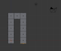 Legs and Pelvis
 -
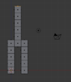 Torso
Torso -
 Arms
Arms


To be safe, remove any double vertices you may have inadvertently created:
- In Vertex select mode, press A until all vertices are selected.
- Make sure that you are in Edit Mode, Press RMB to bring up the Vertex Context Menu.
- Scroll over Merge Vertices, and then select By Distance.
Now check your work:
- Return to Object Mode by pressing Tab .
- Make sure the viewport draw type is Solid. (Press Z if it isn't.)
- Rotate the viewpoint and examine the body from every side (it might be useful to return to perspective view for this).
This is easily fixed. To create a face:
- Press Tab to go back into Edit Mode.
- Select four vertices.
- Press F (or choose Mesh → Faces → Make Edge/Face from the 3D View header).
- Note that you can also make edges with this tool if you select two vertices.
Adding the Head
[edit | edit source]
- Move the 3D cursor to a point above the neck by clicking with the LMB .
- Adjust the cursor position in orthographic top, front and side views ( Num7 , Num1 , and Num3 respectively) until the 3D cursor is about where the center of the head should be. It may help to use Shift + S → Snap → Cursor to Grid.
- Make sure you're in Edit Mode with a 3D View window active. (If you create the head in Object Mode, it will be a separate object from the body, and changes to the body later in this tutorial won't affect the head.)
- Create a sphere using Shift + A → Mesh → Icosphere.
- Leave the default settings for subdivisions and size in the bottom left of the screen. (Note: Your computer may slow down if you set subdivisions above 6)
You should now have a small sphere at the top of the body. To make it more proportional to the body, resize it using the scale tool:
- Make sure you're still in Edit Mode, with a 3D View window active and the head selected.
- If necessary change the pivot point to Median Point.
- Activate the scale tool by pressing S (or Mesh → Transform → Scale).
- Move the mouse pointer until the head is the size you want.
You may also adjust its position using the grab tool:
- Make sure you're still in Edit Mode, with a 3D View window active and the head selected.
- Activate the grab tool by pressing G (or Mesh → Transform → Grab/Move).
- Move the mouse pointer until the center of the head is where you want it.
|
If you deselect the head and then decide that you want to select it again:
|
Now check your work:

- Return to Object Mode by pressing Tab .
- Make sure the viewport draw type is Solid. (Press Z if it isn't.)
- Rotate the viewpoint and examine the body from every side. Make sure that the head connects properly to the neck.
Save Your Work
[edit | edit source]You will continue working on your simple person model in the next module.
To save the scene in a .blend file:
- Press ctrl + S (or select File → Save).
- Navigate to the directory (folder) where you want to write the file.
- Type a filename in the text box to the left of the "Cancel" button.
- Click LMB on the "Save Blender File" button.
Smoothing Your Simple Person
[edit | edit source]|
|
Applicable Blender version: 2.57. |

Few real-life objects have perfectly sharp edges. People, in particular, consist of mainly smooth surfaces. How does one model a smooth object using flat faces and sharp edges?
In this module, you'll learn how to smooth a mesh by using subsurfaces and smooth shading.
You'll need the simple person model from the previous module. If you haven't done it, either go back and do it now or download the pre-made model from Yosun Chang's website at http://www.nusoy.com/blender.
If the model doesn't look solid, your Viewport Shading setting may be set to Wireframe. To switch to Solid shading:
- Activate the 3D View window.
- Press Z .
Subsurfaces
[edit | edit source]
So far, all the meshes you've created have had sharp edges, giving them a faceted appearance like that of a cut diamond. To model a smooth object (like a human body) you might think you need a huge number of vertices and faces. Subsurfaces partly solves this problem by automatically subdividing a mesh into a finer mesh suitable for smooth rendering.
You subsurface in Blender by adding a subsurf modifier to an existing mesh object. A modifier is simply an algorithm (automatic process) which can be added to an object. (Blender modifiers are analogous to Photoshop adjustment layers.)
To get started, make sure Blender is in Object Mode, with only the simple person object selected:
- If Blender is in Edit Mode, press Tab .
- To select the simple person, RMB on it.
To add a subsurf modifier to the selected object:
- Click on the modifiers tab (wrench icon) in the Properties window.
- Add Modifier → Subdivision Surface.
You could also add subsurf modifier by pressing Ctrl + 1Key .
The object's appearance should immediately become more faceted and more rounded. In addition, several subsurface controls will appear in the Modifiers tab.
|
The modifier has been added, but it hasn't actually been "applied" yet. (Applying a Blender modifier is analogous to flattening a Photoshop adjustment layer.) |
The model may include some double vertices. To get rid of these:
- Edit the model in Vertex select mode.
- Select all vertices.
- Mesh → Vertices → Remove Double
- Try again.
You need to look in to upgrading (or possibly even downgrading) your graphics drivers. Having the right graphics driver can avert many problems.
What just happened? The default subsurf modifier (one level of Catmull-Clark) subdivided each face of the object into four smaller faces that are progressively angled. This softened the sharp edges of the original model where faces met at 90-degree angles.
Controls
[edit | edit source]For this model, one level of subsurf isn't quite enough. To increase the number of levels to two, just increase the number in the text box directly underneath Subdivisions. The View setting controls the number of subdivision levels visible in the viewport. This is very useful when you have a high-poly scene, just decrease the number of visible subdivisions to speed up viewport action.
You can specify additional levels of subsurfing to be used during renders. For extra smooth renders, you might want three levels of subsurfing. Set this with the Render control immediately below the View control.
The Apply button applies the modifier to the mesh. Do not click it yet. We'll be playing with the model a bit longer before we apply the changes. While useful with some modifiers, applying a subsurf modifier produces a very complex mesh, and there's no need to do so here.
Remember that you can undo any accidental modifications with Ctrl + Z .
Blender can combine a series of modifiers by stacking them. For this reason, the Modifier tab includes buttons for arranging and removing modifiers.
You can hide edges created by the modifier by activating the Optimal Display toggle button. The effect is especially clear with the Wireframe draw type.
You can edit the mesh in modified form (without actually applying the modifier) by activating the Adjust edit cage to modifier toggle button, a small button with a triangle and vertices, to the left of the Up/Down arrows (the arrows are for changing the position of the modifier in the stack) in the Modifier panel. ![]()
Try this out:
- Press Tab to enter Edit mode.
- Make sure Blender is in Vertex select mode.
- Note that the vertices no longer lie on the surface of the object.
- Activate the Adjust edit cage to modifier button.
- Now all vertices lie on the surface of the object, and you can adjust the (modified) vertices directly. However, any additional vertices created by the modifier cannot be directly edited without applying the modifier.
You will be editing the boxy version of the simple person awhile longer, so before continuing, deactivate the Apply modifier to editing cage during Editmode button.
Smooth Shading
[edit | edit source]Subsurfaces do a good job of smoothing out corners in meshes. Even with two levels of subsurfaces, however, the simple person does not look completely smooth; when viewed close up, it has a scaly appearance. This is because each face is flat shaded—shaded to resemble a flat surface—resulting in sudden changes in brightness at most edges. For a smooth object, you want smooth shading, which smooths out the changes in brightness.
- Go to Object Mode.
- Set the draw type of a 3D View window to "Solid".
- Select your subsurfed object.
- In the Toolshelf on the left, look for a caption called Shading. Under it should be a button called Smooth.
- All the mesh edges will be smoothed out, leaving no sudden changes in brightness. The faces blend smoothly into one another, making the edges nearly invisible. If the icosphere has not smoothed properly and is dimpled, enter Edit Mode by pressing Tab , select all vertices (A) and recalculate the normal direction (CTRL+N). This is also available in the Toolshelf under Normals.
- Click the other button under Shading in the Toolshelf, named 'Flat'.
- The edges will reappear. Now you know the difference between Flat and Smooth.
- Since the model looks better with smooth shading, click LMB on the "Smooth" button again.
Note that if you didn't have subsurf enabled, then the mesh wouldn't look much different. This is because smooth shading doesn't affect the mesh shape, it just changes how the computer draws the triangles.
Smooth shading also removes a lot of definition. A good way to get rid of this is simply to add a subsurf modifier like you just did. The modifier will not only require fewer vertices, but add definition.
-
 Flat Shading
 -
 Smooth Shading


Save your work. You will continue refining this model in the next module.
Additional Resources
[edit | edit source]- Flat shading at Wikipedia.
- Gouraud shading at Wikipedia.
- Phong shading at Wikipedia.
- Subdivision surface at Wikipedia.
- For more about modifiers, see the Blender Manual page on "The Stack" at http://wiki.blender.org/index.php/Doc:Manual/Modifiers/The_Stack
- For more about Blender subsurfaces, see the Blender Manual page on "Subdivision Surfaces" at http://wiki.blender.org/index.php/Doc:Manual/Modeling/Meshes/Subdivision_Surfaces.
Improving Your Simple Person
[edit | edit source]|
|
Applicable Blender version: 2.57. |
In this module, you'll edit a subsurfed mesh using the scale and grab tools, all the while improving your character.
You'll need the simple person model from the previous module. If you haven't done it, either go back and do it now or else download the pre-made model from Yosun Chang's website at http://www.nusoy.com/blender.
Widening the Torso
[edit | edit source]To be realistic, the simple person's torso needs to be three times wider. In order to keep the torso symmetrical, you'll expand it by scaling both sides from a central point.

Select the sides of the torso:
- Enter edit mode on the simple person.
- In the 3D View header, set Face select mode.
- From the 3D View header, choose Pivot → Median Point.
- In the 3D View header, make sure Proportional Edit button is off.
- Select the two faces on both the left and right sides of the torso, between the armpits and the waist.
 When editing in solid mode, the vertices, edges and faces on the back side of the model are, by default, invisible. This feature can be toggled by clicking LMB on the Limit selection to visible (called in older versions, "Occlude Background Geometry") button in the 3D View header. Toggle it on and off a few times and observe how the back faces appear and disappear. |
We will now scale the torso with the scaling tool:
- Activate the 3D View window and press S , X .
- Adjust the amount of scaling. Either:
- Move the mouse pointer until the torso is the width you want.
- or
- Press 3
- Confirm and exit by pressing Enter or clicking LMB .
|
Scaling faces causes adjacent edges and faces to move, due to their shared vertices. You cannot separate a face or edge from its vertices. |
Continue selecting different parts of the torso and scaling them to get more practice using the above scaling methods.
Bending the Arms
[edit | edit source]
When you've got the basic shape of the torso, make the person hold up his hands. You'll do this by deleting the forearms and then extruding upward from the elbows.
Select both forearms:
- Enter edit mode on the simple person.
- In the 3D View header, set Face select mode.
- With the 3D View window active, press A until all vertices are deselected.
- Select the five faces at the end of the forearm.
Now erase them:
- Press X to open the Delete menu.
- Choose Faces.
The forearm will disappear, leaving a hole. Don't panic; we'll fix it later. Now to make the arm point upwards:
- Select the top face of the last remaining "arm cube".
- Extrude the region upward by two Blender units E , 2 and confirm with LMB or Enter .
The hole in the elbow is caused by a missing face. To fill in the missing face:
- Deselect all vertices.
- Select the four vertices surrounding the missing face.
- With the 3D View window active, create the face using either
- Mesh → Faces → Make Edge/Face
- or
- F
|
If a Make Faces menu appears when you try to fill the hole, it may be that you have some doubled vertices. You can remove doubles by selecting the whole mesh in edit mode, then pressing W and in the appearing menu "Remove Doubles" and try again. |
The new face should be smooth. If it isn't, make it so, using Mesh → Faces → Shade Smooth.

Go through the same steps (erase, extrude, and fill) on the other arm. Be sure to deselect all vertices in the first arm before selecting any in the other arm. If you have difficulty making the arms symmetrical, undo your work and go through the steps simultaneously on both arms.
Making Feet
[edit | edit source]To make feet for your simple person, you subdivide the ends of the legs and pull the front edges forward.
- Edit the simple person in Face select mode.
- Select the two bottom faces of the legs (front of the feet) by clicking RMB on the first and then Shift + RMB on the other.
- Subdivide both faces, either with:
- W Subdivide
- or
- Mesh → Edges → Subdivide
Each face gets subdivided into four smaller faces.
Now select the front edges and pull them forward:
- Switch to Edge select mode.
- Press A until no edges are selected.
- Select the four bottom front edges of the soles (two for each feet) (where the toes should be).
- Press G and limit movement to the Y axis.
- Move the mouse pointer until the feet are the length you want.
- Confirm and exit by pressing Enter or Space or clicking LMB .

Reshaping the Head
[edit | edit source]When you're satisfied with the torso and limbs, you should do something about that head. A bit too spherical, isn't it? You can elongate it by scaling along the Z axis.
When scaling the head, you want to make sure that it stays connected to the neck.
First, place the 3D Cursor at the base of the head, where it meets the neck. An easy way to do this is as follows:
- Go into Vertex select mode.
- Make sure the Limit selection to visible option is "off".
- Select the vertex at the base of the head using RMB .
- Snap the cursor to this vertex using Shift + S Cursor to Selected
Now select the entire head:
- Hover the mouse over a vertex/edge/face of the head
- Press L to select all parts linked to that part.
|
This works even when the head and body meshes overlap, so long as they aren't linked together anywhere. |
Tell Blender that you want to pivot around the 3D Cursor by changing the pivot point to 3D Cursor on the Pivot menu (the small button located to the left of the 3D Manipulator button).
Now scale the head along the Z-axis, using the scale tool ( S , scaling by 1.5 should be about right).

You'll need this simple person later, so remember to save your work!
Spinning a Simple Hat
[edit | edit source]|
|
Applicable Blender version: 2.57. |
In this module, you'll create a hat for your simple person. Along the way, you'll learn how to use the Spin tool and use layers.
Creating a Generatrix
[edit | edit source]For future convenience, you'll create the hat as a new object in the scene containing the simple person. If you haven't created the simple person, either go back and do it now or else download the pre-made model from Yosun Chang's website at http://www.nusoy.com/blender.
Start by changing layers to layer two, then add the basis for your hat:

- Make sure you're in Object Mode (so that a new object will be created).
- Click LMB on the second little square, this will make the viewport display layer two. (The top row is for layers 1 to 10, the bottom for 11 to 20, so layer 2 is immediately to the right of layer 1; layer 6 is across the space from layer 5.)
- Go to orthographic front view by pressing Num5 , then Num1 .
- Create a mesh circle at the cursor, by activating the 3D View window, pressing shift + A and choosing Mesh → Circle.
|
The new circle will probably look more like a line segment than a circle. If so, it's because you're viewing the circle edge-on. |
The new mesh object doesn't actually have to be a circle. You could use any sort of mesh object here because you're about to reshape it into a custom 2D mesh (called a generatrix) that describes the profile of your hat. More precisely, the generatrix describes one side of a vertical cross-section through the hat. You'll want your generatrix to have a slope; it should be higher on one side (which will become the top of the crown) than on the other (which will become the brim).
- The newly-created mesh should be selected. If it isn't, select it by clicking RMB on it.
- Press Tab to edit the mesh.
- Activate Vertex select mode.
- Press A until all vertices are selected.
- Press X to erase all vertices.
|
Some users are confused as to the purpose of creating the mesh only to delete it afterwards. The point of this process is to create a new "blank" object which you can then shape into a hat. |

Now draw your generatrix, starting with the brim and sloping upwards toward the top of the crown:
- Make sure you're still in orthographic front view.
- Press Ctrl + LMB to create the first vertex.
- Press Ctrl + LMB to one side of that vertex to extrude another vertex, connected to the first by an edge.
(If this doesn't work, make sure you are in vertex select mode.)
Keep adding vertices until you're satisfied with the shape of your generatrix. You can always undo using Ctrl + Z or go back and adjust the positions of particular vertices using the grab tool.
The mesh is then spun around an axis perpendicular to the viewplane. You want to spin around a vertical axis, so press Num7 to switch to top view.
Spinning the Hat
[edit | edit source]
Now, let's actually spin the hat:
- Move the 3D cursor to the vertex you want to spin around by pressing LMB on it. You can also use the snapping tool for positioning the cursor more precisely by pressing Shift+S after selecting that specific vertex. Cursor to selected positions the cursor.
- Press A to select all the vertices. The Spin control only spins vertices that are selected.
- Press Alt+R to activate the Spin tool.
- The Spin tool is also available in the Tool Shelf under Add
If you spin the hat in front view, your hat will be flat. You have to spin the hat in top view.
- The Spin tool is also available in the Tool Shelf under Add
You should now see 90° of a generatrix! To spin your hat all the way round, press F6 or look in the Operator Panel just below the Tool Shelf. There should be an input slider named Angle, change this value from 90 to 360. There should also be a slider called Steps, increase the value from 9 to 15.
If your hat has a large hole in the center, you must have accidentally moved the 3D cursor away from the vertex you picked in step 1. Try again.
Remember that if you spin an object 360° there will be a double row of vertices at the row of vertices you spun. To fix this, press A to select all vertices, press W and select Remove Doubles. Note that this will only work in vertex select mode.
You may also want to merge the vertices at the top of the hat. Do this by selecting all the vertices at the top with C and pressing Alt + M → At Center. You may have to do this twice as some vertices might be beneath each other.
You have more than one 3D View window, so Blender is asking which window to perform the spin in. Click LMB on the window that is showing top view.
Smoothing Your Hat
[edit | edit source]
You'll probably have noticed that normal hats aren't usually as faceted as yours! To change this, first press Tab to go back to Object mode then change the shading to Smooth (available on the Tool Shelf). If there are unexpected black marks, try recalculating the normals.
- Switch to Edit mode and open the Mesh menu in the 3D View Header.
- Normals → Recalculate Outside.
Next, add a Subsurf modifier to the hat and set the subdivisions to two, as you did in the "Detailing Your Simple Person 1" module.
- Click on the modifiers tab (wrench icon) in a Properties window.
- Add Modifier → Subdivision Surface.
Save your work. You'll need this scene for the next module.
Additional Resources
[edit | edit source]- Surface of revolution at Wikipedia.
- http://www.youtube.com/watch?v=-mPtxa_MEPA Ira Krakow's Hat Creation Video Tutorial, based on this page.
Putting the Hat on the Person
[edit | edit source]|
|
Applicable Blender version: 2.70. |
Once you're satisfied with the shapes of individual objects, you'll want to combine them into a coherent scene. You do this in Object Mode.
In this module, you'll learn how to move objects to and from layers. You'll also learn how to rename and parent objects, and you'll get an introduction to Outliner Windows.
You'll need the person-and-hat scene from the previous module. If you haven't done it, either go back and do it now or else download the pre-made model from Yosun Chang's website at http://www.nusoy.com/blender.
Adjusting an Object's Median Point
[edit | edit source]
- Load the person-and-hat scene.
- Make sure Blender is in Object Mode.
- Switch to Layer 2, select the hat and press M . A dialog box will pop up for you to choose which layer to move it to. Either press 1 (the number on top of the keyboard, not the numberpad) or select the first box in the popup.
- Select the person you made earlier.
Just as you did in Edit Mode, you can specify the pivot for rotating and scaling objects in Object Mode. If you just finished the previous module, the pivot is probably set to "3D Cursor". If so, change it back to "Median Point".
In Edit Mode, the "Median Point" for pivoting is the geometric center of all selected vertices, edges, or faces. In Object Mode, however, it's the origin of the selected object's local coordinates, indicated by an orange dot. In other words, the origin might lie far from the object's geometric center.
You can use buttons in the Tools Shelf to reunify an object's origin with its geometric center:
- With Blender in Object Mode, click LMB on Set Origin in the Tool Shelf (under the "Edit" sub menu of Tools) and select Origin To Geometry (Blender 2.70: "Object" -> "Transform" -> "Origin to Geometry") to move the selected object's origin to its geometric center (without changing the object's appearance).
|
When more than one object is selected, Blender uses the average of their median points as the median point for pivoting. |
This can be useful when you want a better picture of your object. With the origin set to the person's geometric center, you can now snap the object with Shift+S to the 3D cursor. This will let you view more of the model at one time and make for a faster editing workflow.
Positioning the Hat
[edit | edit source]
Once you have the hat properly oriented, move it into position on the person's head. The grab tool enables you to position objects in Object Mode in the same way you positioned vertices, edges, and faces in Edit Mode.
- Make sure Blender is in Object Mode.
- Click RMB on the hat object to select it.
- Activate the grab tool by pressing G .
As you move the mouse pointer, the hat will move around in the viewport. By default, the movement plane is perpendicular to the view axis, so the hat will move differently depending on which viewpoint you're working in.
Just as in the Edit Mode grab tool, you can:
- Restrict the direction of motion by pressing X , Y , or Z . Press once to move parallel to a global axis, twice to use a local axis. (Press the same key a third time to return to view-plane motion.)
- To restrict motion to the global X-Y plane, lock the global Z by pressing Shift + Z .
- Hold down Ctrl to restrict motion to discrete steps (typically one Blender unit).
- Hold down Shift to get finer control over the motion.
- Click LMB or press Enter to finalize the position and exit the tool.
- Click RMB or press Esc to return the object to its previous position and exit.
Use two different orthographic views to position the hat on the person's head. You will probably want to scale the hat to make it fit the person's head better. When you are doing this along the X or Y axis, make the changes symmetrical by specifying the axes you want scaling to be constrained to. This option is available in the Operator panel (just below the Tool Shelf) and also by pressing F6.
Parenting the Hat to the Person
[edit | edit source]
Once you have the hat properly sized and positioned on the person's head, you'll want it to stay there. In order to maintain such a cozy relationship between two objects, you'd have to remember to select them both before rotating, moving, or scaling. A drastic solution might be to join them into a single object using Ctrl + J .
A better compromise is to Parent the hat to the person. Parenting creates a relationship between two objects, such that certain changes to one object (called the Parent object) automatically affect the other (called the Child object). Changes to the child, however, do not affect the parent.
Note that an object can have many children, but only one parent.
Since the person is bigger than the hat, it's logical to parent the hat to the person (meaning: parent = person, child = hat) instead of vice versa.
- Make sure Blender is in Object Mode.
- Click RMB on the hat object to select it.
- Click Shift + RMB on the person object.
- Both the person and the hat should now be selected. The order of selection is important here.
- Press Ctrl + P to parent the hat to the person.
- Select Object. The most recently selected object becomes the parent of all other selected objects.
|
Pressing P in the object mode instead of Ctrl + P will start the Blender game engine. To stop the game engine, press Esc . |
Now when you move the hat you will see a line from the hat to the person, indicating that the person is the hat's parent. And if you move the person, the hat will move with it.
You may get an error saying something like Loop to Parents, fix this by clearing all previous parents with Alt + P .
Renaming Objects
[edit | edit source]
When you have multiple objects in a scene, it helps to give each one a name.
Click on the Objects tab in the Properties panel (the one with a box icon).
- Now select the hat by clicking RMB on it.
- At the very top of the tab you should see a dialog box with the name of your object
- The hat's name might be something like "Circle" depending on which mesh primitive you first built the hat from.
- Click LMB on the dialog box and type in a more descriptive name like "Hat".
You have now changed the name of the hat's object datablock. This name change will be reflected in the Outliner, which we will look at shortly.
Now select your person by clicking RMB on it and repeat the process, changing the name to something like "Person".
Outliner Windows
[edit | edit source]
Once you give objects names, it helps to have a way to find objects by their name and parent. This is exactly what the Outliner is for and it comes in very handy when you are working with a large scene. The Outliner is usually just above the Properties panel. You may want to pull it down a bit to see it more clearly.
You'll notice that all the objects in your scene (Person, camera etc) are listed and that you can select these objects by clicking LMB on them. And if you click RMB on an object, a menu will pop up with options like Select, Deselect, Delete etc. If you select the Person and then click the "+" sign to its left, you will see that the Hat is listed below the person. This is because Blender lists all children objects beneath their parents.
On the right of each object there are a series of icons which represent the state of the object. For example, the eye icon means that your object is visible in the 3D viewport. You can turn off its visibility by clicking LMB on the eye, which will turn grey; click again on the eye to make it visible. If you hover the mouse over the icons a text box will pop up with a description of what that particular icon does.
Good on ya' mate!
[edit | edit source]Congratulations!! You have now finished your simple character. Pat yourself on the back, and have a celebratory coffee! (Or pop!)
Additional Resources
[edit | edit source]- Outliner at http://www.blender.org/development/release-logs/blender-235a/outliner/
- Gestures at http://www.blender.org/manual/modeling/meshes/editing/basics/translation_rotation_scale.html
- Parents at http://www.blender.org/manual/editors/3dview/object/relationships/parents.html
Overview
[edit | edit source]|
|
Applicable Blender version: 2.57. |
In 3D graphics, materials and textures are nearly as important as shapes. Scenes would be boring if all the objects were gray.
The material system in Blender allows you to model a wide variety of materials and how they interact with light. The next few modules will introduce the available options.
|
Note that material and texture settings are renderer-specific. This page and the following ones describe settings appropriate to the Blender Internal renderer, which is the one selected by default when you open a new Blender document. Other renderers (both built into Blender and external) are available; you will learn about these later, in Advanced Rendering. |
Material versus Texture
[edit | edit source]A material defines the optical properties of an object: its color and whether it is dull or shiny. A texture is a pattern that breaks up the uniform appearance of the material. Very few objects in the real world have completely uniform surfaces. Instead most of them have patterning or variation in color: consider the grain in a piece of wood, the pile in a carpet, or the mortar in a brick wall.
Blender allows textures to influence materials in various ways, such as altering their colors. Multiple textures can interact with each other to produce interesting effects.
Note that textures have to be attached to materials to affect objects, you cannot apply a texture to an object without a material.
Other Material Settings
[edit | edit source]Additional settings you can specify for a material include shaders, ray-tracing and halo.
Shaders determine how the appearance of a material varies with the angle of the light: diffuse shaders give a non-shiny look, while specular shaders give a mirror-like finish. Blender's material settings always involve both kinds of shaders, but you can adjust a material's diffuse and specular colours separately to control their respective effects; if you set the specular colour to black, the surface will no longer produce reflections.
Ray-tracing is a technique for modeling the physical path of light through the scene. It is capable of producing exquisite reflection and refraction effects, including different degrees of reflectivity, translucency and transparency, and representing materials with different indexes of refraction. Blender provides two separate groups of ray-tracing settings, one for reflection of light and the other for its transmission through the material. You can control these settings on a per-material basis.
Halo rendering means an object no longer looks like solid matter, instead it appears to be made of bits of light. This can be used for real-world effects like fire, smoke and plasma, or to create fantasy effects with no connection to reality.
Note that reflections produced by ray-tracing are separate from that produced by the specular shader: the former are controlled by the material's mirror colour, while the latter is controlled by its specular colour.
Reflection is done in two different ways because, while ray-tracing produces the most realistic renders, it is also very CPU-intensive. It is therefore best to apply the ray-tracing effects when you're completely done with your modelling to help reduce high CPU usage. Enough practice with ray-tracing can also help you get stunning effects with just few clicks without you having to do much trial and error. You would do well to dedicate at least a few hours of your time to experimenting with it, so that in a future real production situation, you will be spared all that hassle.
Types of Textures
[edit | edit source]When you create a texture in Blender, you will see a popup menu listing a whole lot of different types for the texture. The Image or Movie texture type lets you use a scanned image to texture your object: for example, you can scan an actual piece of metal and use that to give your object a realistic metallic appearance, or use a photograph of an actual brick wall to texture the wall of a building model, and so on. You could even use a movie, which plays during the animation of the scene.
The other texture types are called procedural, which means the textures are generated according to algorithms built into Blender itself. These can be useful for simulating various effects when you don’t have an image of the real material handy; they can also be applied to augment the appearance in various ways. For example:
- using a “cloud” texture to “dirty-up” a material
- or
- using one texture as a stencil to create an amalgam of two other textures.
Additional Resources
[edit | edit source]- Diffuse reflection at Wikipedia.
- Ray tracing (graphics) at Wikipedia.
- Specular reflection at Wikipedia.
- Texture mapping at Wikipedia.
Quickie Material
[edit | edit source]|
|
Applicable Blender version: 2.59. |
In this module, you will create a new material called "Green Ooze". Along the way, you will learn how to alter the diffuse, specular, and mirror colors of a material.
Your First Material
[edit | edit source]
The cube in the default scene (which you get from File → Load Factory Settings) has a simple grey color. Now click on the Materials context ![]() in the Properties
in the Properties ![]() window.
window.
The materials context contains various menus, but for now you only need diffuse, specular and mirror. The material is named and linked in the panel above the preview window. (Linking is a feature that allows materials to be shared between multiple objects (or datablocks). Changing a material affects the appearance of everything it is linked to.)
The first row of the window above the preview window indicates that:
- there is one material assigned to this object and its name is "Material".
The second row of controls indicates that:
- The current selected material's name is "Material".
- This material will only be saved if it's in use.
- It is not a "Nodes" material.
- Instead of being linked directly to an object, the current material is linked to a datablock.
To rename the material, click LMB on the name and enter the name you want.
To unlink the material, click LMB on the X button to the right of the material name ("Material"). Do this now. This deletes the link to the datablock, removing the material from the mesh. As a side-effect, most of the panels in the Material context disappear. You will see in a moment, however, that the material still exists. It hasn't been deleted; it is simply no longer in use.
At this point, you could click LMB the "New" button to create a new material, but instead we are going to reapply the old material:
- Click LMB on the
 button to the left of the "New" button.
 - You'll see a nifty drop-down list containing all materials you've created so far. Choose 0 Material.
Materials whose names are preceded by "0" in this list are not in use. By default, Blender doesn't save such materials when it saves the scene. Thus, you can delete a material from the list by saving the scene and then reopening it. You can override this behavior by toggling the "F" button "on" for unused materials you want saved.
Your materials will be much easier to find and manage if you give them brief, descriptive names you can recognize at a glance. Change this one's name to "Green Ooze". In addition, naming of your materials and other objects in your scene is useful when such components of your scene will be appended in another scene of a different Blender file. Naming your materials and other stuff in the scene will enable you to choose the right objects and materials you need whenever you wish to append just a portion of a whole bunch of work you did. For instance, you're working on a new Blender project, but felt the material you used in this Blender file is worth it. Instead of going through the pain of creating a new material (of course you guessed in the initial one in getting the right material appearance), you just append the material to your new work. Pretty simple! Make naming a habit, as it's much used in a production environment.
Specifying Colors
[edit | edit source]Simple materials are specified by three colors: diffuse, specular and mirror. Rectangular patches (swatches) of the colour in their own panel in the Material context allow you to see and change each of these. Diffuse color is the basic underlying color of the material, rendered by the diffuse shader. Specular color is for highlights (small bright spots on a shiny surface) as rendered by the specular shader. Mirror color is for true reflections rendered using ray-tracing.
There are many ways to define colours. Blender supports three:
- RGB: By specifying relative amounts of red, green and blue primary colours, by giving a number from 0.0 to 1.0 for each component. For example, (R, G, B) = (0, 0, 0) specifies black (no colour at all); (0, 1, 0) is full green; (1, 1, 0) (full red + full green) is yellow; (0.5, 0.5, 0.5) is 50% grey, and (1, 1, 1) is full white (maximum intensity of all components). Note that this is additive mixing of colours, which is what happens when you shine lights of different colours onto a white screen, not the subtractive mixing that takes place when you mix different-coloured paints or inks on paper or canvas.
- HSV: By specifying a hue (colour position on the rainbow) together with a saturation (strength of colour, from garish down to pastel, with zero giving shades of grey) and value (brightness). This is generally considered to be easier to use than RGB notation when you are trying to create new colours (as opposed to copying a colour spec from somewhere else), since it is easier to predict what the likely result will be. HSV is commonly represented on a colour wheel, where the hue is the angle around the circle, saturation the distance from the centre, and value controlled by a separate brightness slider (as shown below).
- By specifying a 6-digit hexadecimal number. This is just an alternative form of RGB notation, commonly used for colour specifications in Web pages.

If you click on any colour swatch, the colour picker will pop up, allowing you to change the values. This is the most intuitive way. The window that appears will look like this and will include the following (Figure 2):
- A color wheel to change the color as you want. In HSV mode, H corresponds to angle around this wheel, while S corresponds to distance from the centre.
- Three color sliders that will change if you change the color in the colorwheel. You can also change the values with the sliders.
- A slider that controls the intensity of the color. This corresponds to the V in HSV.
- A pipette capable of sampling colors from any Blender window or render window.
- Buttons that can change it to "HSV" or "HEX" mode.
- Alternatively you can specify hue, saturation and value components by clicking LMB on the "HSV" button and pushing the sliders around accordingly.
- You can also press the last button and enter the hexadecimal (or HEX) code. This is simply a different representation for RGB, where the hex digits represent rrggbb.
HSV is probably the most easily understandable way of specifying and experimenting with colours. However, as is common with most computer systems, all colours in Blender are represented internally as RGB.
If you want to get rid of the window just click LMB anywhere else.
|
Duplicate intensity sliders? There are two ways to control the intensity of the colour: there is the vertical intensity slider at the right of the colour picker popup, and there are also the intensity fields at the bottom of the Diffuse and Specular panels (above), the final intensity being the combination of both values. Why two different ways? Partly this is to allow a quick way to moderate or intensify the diffuse or specular components, without having to change the actual colour specification. But more importantly, this is to ensure that intensities are never set to 100%. The reason is that this can cause rendering calculation problems, leading to total light intensities accumulating to infinity instead of converging to a finite value. This is probably not a big issue with the Blender Internal renderer, but can become a problem with more advanced renderers. |
The most used method of creating a color of your own is using the color wheel, but because we want to be sure you will get the exact same color as us we will use the sliders. Use the above methods to set the diffuse color to R=0.149, G=1.000, B=0.446 (or use the HEX code: 6CFFB2). If you look in the "Preview" panel, you will see that the material is now bright green.
Most real-life materials (other than metals) don't alter the color of specular light. For this reason, Specular and Mirror are usually left at their default values (white). For green ooze, however, you'll disregard this rule-of-thumb:
- Click LMB the sample rectangle below the Specular window.
- Use the color selection dialog to adjust the specular color and watch the Preview panel to see how this color affects the sample sphere's highlight.
- Set the specular color to R=0.640, G=0.990, B=0.566 (or use the HEX code: D1FEC6).
With these values for Color and Specular, you should be able to get a good ooze later on. The Preview, Diffuse and Specular panel should now look like this:


As you can see, there are many other material buttons. Many of these will be explained in later modules. Suggestions for creating specific materials may be found in the "Every Material Known to Man" module.
Save this scene before proceeding. You will need it for the "Quickie Texture" module, in which you will perfect your ooze.
|
Copying/Pasting Colours: Quite often, you will want to duplicate or move a colour specified in one place to another. If the two colour swatches are simultaneously visible, you can use the eyedropper button in the colour picker. But if they are not, then the easiest way is to bring up the colour picker for the colour you want to copy, switch to the hex display, select the 6 hex digits, and copy them with CTRL + C . Then go to the colour you want to make the same, bring up its picker in hex mode, select the hex digits, and replace them with what you copied using CTRL + V . |
Additional Resources
[edit | edit source]- HSL and HSV at Wikipedia.
- RGB color model at Wikipedia.
- How to Assign a Different Material to Each Face of a Cube at http://www.youtube.com/watch?v=hCYViRJFf5w
Multiple Materials per Object
[edit | edit source]|
|
Applicable Blender version: 2.81a. |

In this module, you'll create a beach ball with two alternating colours. Along the way, you'll learn how to apply multiple materials to a single object.
Many real-life objects have parts which are different colours, or are even made of different materials. One way to model such objects is to make each part a separate Blender object. However, Blender also allows you to assign different materials to parts of a single object.
Set the Scene
[edit | edit source]Begin by opening Blender and removing the default cube.
Now create a mesh for the beach ball:
- With the 3D View window active, press Shift + A ) and choose Add → Mesh → UV Sphere.
- Expand the "Add UV Sphere" panel in the bottom left of the screen, then specify 8 segments and 4 rings.
- The initial result will be crude, but meshes with fewer vertices are easier to edit.
Make the mesh rounder and more organic using automatic subdivision:
- In the "Properties" editor, select the "Modifiers" context (wrench icon).
- Select "Add Modifier" and click Generate → Subdivision Surface.
- For the number of subdivisions, set both the 'View' and 'Render' count to 2.
Get rid of that blocky look:
- Ensure you're in Object Mode.
- Click the object button at the top of the viewport.
- Select "Shade Smooth" from the list of options.
The ball is now round, but a bit prolate. To make it more spherical, scale it by about 1.1 along the X and Y axes. To select the X-Y plane, you select ′not Z′, by using the key combination Shift + Z . The complete sequence is, then, S , Shift + Z , 1.1 .
Colorize Time
[edit | edit source]Now you're ready to begin adding colors to the object:
- Press Tab to put Blender into Edit mode.
- In the Properties editor, select the "Material" button
 .
. - Press "+ New".
- A new material appears in the material slot list, and several additional panels appear below to edit the created material.
- In the "Surface" panel, click on the default white base color and change it to a nice yellow.
- At this point, the entire ball is yellow.

In the "Materials" panel click the "+" button (indicated by the red box in the picture, below) next to the material slot list to create a new blank slot. The "+ New" button will reappear (indicated by the blue box, in the picture below).

Click the "+ New" button and a new material will be created and assigned the empty slot in the materials slot list. Ensure that the new material is selected, then change the base color to blue. Nothing will happen to the beach ball, yet.
Now make a single blue stripe on the ball:
- All the vertices should still be selected from before; make sure the 3D view is active, then hit Alt + A to deselect them.
- Switch to front view with NUM1 , and to "Face Select" mode by selecting the face select button. Which is to the left of the "view" button in the top left of the viewport.
- Select a column of four faces that will make up one stripe of the beach ball (using SHIFT + LMB , or SHIFT + RMB depending on your selection key, on each face):
- In the "Material" property window, select the blue material slot in the list, then click the "Assign" button.

Rotate the view (e.g. NUM6 ) so you can skip past a yellow stripe adjacent to the blue stripe, and select the second column that will become a blue stripe. Work your way around the ball to do this three more times. (Remember we made the sphere with 8 segments; four of these are yellow, and four are blue).
Now you see the benefit of making a sphere with only 4 rings: more rings would have meant more faces in each stripe, and more clicking to select them.
For help with rendering your beach ball, see our Noob to Pro/Render Settings and Noob to Pro/Quickie Render
Metal Versus Plastic
[edit | edit source]|
|
Applicable Blender version: 2.67. |
There are different kinds of shiny materials. Consider the difference between a shiny metallic object, and one made out of a glossy nonmetallic material (like plastic or ceramic). This page will explain some simple techniques for (approximately) mimicking the appearances of these materials using shader settings in the Blender Internal renderer.
For all the following manipulations, start a new Blender document, get rid of the default cube, and replace it with a UV sphere. Set it to be smooth-shaded. Change the lamp falloff to be inverse linear, just to make the scene brighter. Assign the sphere a new default material. It is the settings of this material we will now proceed to play around with.
Making It Plastic
[edit | edit source]
For a plastic or glossy effect, give the material a diffuse colour, but leave the specular colour at white. Increase the specular intensity to something like 0.9.
(In this and the following examples, I used a diffuse colour of #E7398B.)
Making It Metal
[edit | edit source]
Now change the specular colour to be the same as the diffuse colour. (The easy way to do this is to bring up the specular colour picker, click on its eyedropper icon, and use the eyedropper tool to click on the swatch showing the diffuse colour.) Also lower the specular hardness from its default value of 50, to something like 25 or even 12. This will spread out the specular highlight, giving the impression of a surface that is shiny, but not perfectly smooth. Also lower the diffuse intensity, to something like 0.05.
To make the metal more convincing, you may want to choose a more typical metal colour, like grey, copper or bronze.
Making It Ceramic
[edit | edit source]
Let’s try for a glazed-ceramic look, or perhaps some dark, shiny stone like obsidian. Set the specular colour back to white (the easiest way to do this is to switch to HSV view in the colour picker and set the S(aturation) value to 0). Increase the hardness to something like 200 to narrow and intensify the specular highlight. Leave the specular intensity high and the diffuse intensity low.
To get an even more sharply-focused highlight, change the specular shader model from its “CookTorr” default to “WardIso”. The “Hardness” parameter gets replaced with a “Slope” instead; leave this at the default 0.1.
Texture Settings
[edit | edit source]|
|
Applicable Blender version: 2.68. |

In the Properties ![]() window, you will find the Texture
window, you will find the Texture ![]() context, which looks like at right.
context, which looks like at right.
At the top you will see a row of three icons ![]() , which indicate texture settings to view and change:
, which indicate texture settings to view and change:
 World Texture — a texture to use for the sky backdrop
 Material Texture — a texture associated with the currently-selected material
 Brush Texture — a texture used for some other purpose.
There are two main types of textures in Blender:
- Image/Movie textures
- Procedural textures (all other types in the Type menu).
An image/movie texture allows a two-dimensional image (which might be static or moving) to be wrapped around the surface of a three-dimensional object in some way. Alternatively, a procedural texture directly maps a predefined three-dimensional mathematical function to the surface coordinates of the object.
The “Coordinates:” popup menu defines how positions on the object surface are mapped to positions within the texture coordinate space. All of these options specify automatic mapping algorithms, except one: the “UV” option. This one lets you work within the UV/Image Editor, where you unwrap the surface of the mesh onto a flat rectangle showing the texture image (this really only works with Image/Movie textures), and then move sections of the mesh around to make them show corresponding parts of the texture.
The “Projection:” popup menu further controls how the two-dimensional surface of the object is mapped to a two-dimensional Image/Movie texture. It seems to have no effect for procedural textures.
The “Offset:” and “Size:” X, Y and Z values allow simple adjustments of the position and scaling of the texture. Note that the size values work the opposite way to what you might expect: larger values here make the texture smaller along the corresponding dimension.
The image at right shows the common settings panels for all material texture types. Additional panels will appear depending on the chosen texture type; the settings shown are for the “None” texture, which is the same as having no texture at all.
Material Textures
[edit | edit source]A material may have more than one texture associated with it. At the top of the material texture settings (see above), is a list of the texture slots associated with the material. Slots may be empty (unused), and slots containing a texture may be enabled or disabled, by checking or unchecking the box at the right of the list item. Disabling a texture slot stops it having an effect on the material, which is the same as deleting the texture from the slot altogether, except it is easier to revert. This can be useful when trying to debug the effect of a combination of textures on the material.
World Textures
[edit | edit source]
You previously saw how to set up colours for the sky in the World Settings; you can also add a sky texture as well.
World texture settings look similar to texture settings: again there are a number of slots, and there are mapping and influence options. But the mapping coordinates types are different (and there is no UV option), and the influence types are more limited.
|
Note that the only Influence checkbox checked by default is “Blend”. |
If you’re wondering why your texture definition here is making no difference to your sky, either make sure the “Blend” checkbox is checked in your World ![]() settings, or check the “Horizon” Influence box here if you don’t want a sky gradation.
settings, or check the “Horizon” Influence box here if you don’t want a sky gradation.
Image Textures
[edit | edit source]|
|
Applicable Blender version: 2.70. |
Image Texture Settings
[edit | edit source]
To understand how the texture settings apply to image/movie textures, start with an example texture. A nice simple one is this checkerboard at right—don’t forget to download it in (or convert it to) PNG format, as Blender cannot use an SVG file as a texture.

Start a new Blender document. Note the default cube already has a a default grey material, called “Material”, and this already has a single texture, called “Tex”, of type “None”, which means it has no effect.
|
Before proceeding, go to the World |

Under the Texture ![]() context of the Properties window, with Material Texture
context of the Properties window, with Material Texture ![]() selected, change the texture type to “Image or Movie”. You will immediately see some new panels pop up in the texture context. Look for the Image panel, as at right. This initially contains a popup menu icon for selecting from any previously-loaded images (this will start out empty), a “New” button for using one of Blender’s predefined test textures, and an “Open” button for loading an image from a file.
selected, change the texture type to “Image or Movie”. You will immediately see some new panels pop up in the texture context. Look for the Image panel, as at right. This initially contains a popup menu icon for selecting from any previously-loaded images (this will start out empty), a “New” button for using one of Blender’s predefined test textures, and an “Open” button for loading an image from a file.
Click the “Open” button, and select your previously-downloaded or converted PNG version of the example checkerboard texture.

Now a whole lot more settings will become visible. From the top, the panels are:
- Preview — gives you a simple display of how the texture looks.
- Colors — lets you make simple adjustments to the image brightness, contrast etc.
- Image — lets you choose from any already-loaded images, and shows you the pathname of the file the image was loaded from. Note the two arrows in a circle to the right of the pathname display: clicking this will tell Blender to reload the image from the file, which is useful if you make changes to it in an external image editor.
- Image Sampling — controls how the image can be interpreted in a different way from straight pixel values.
- Image Mapping — lets you crop the input image, and apply fixed numbers of repetitions to it along each axis, even before it goes through the usual texture-tiling repetition process.
- Mapping, Influence — these are more general panels that apply to all types of textures. They will be discussed in more detail shortly.
|
Image packing: the icon to the left of the image pathname lets you pack a complete copy of the image into the .blend file, so it no longer keeps reading the original image file. This can be useful if you want your .blend file to be self-contained, particularly if you want to send it to others. On the other hand, if your workflow depends on coordinating with someone else doing the image editing, it may be more convenient to leave it linking to a separate image file. |

If you render F12 now, you should end up with an image like this. Notice in the Projection menu (Texture → Mapping) the initial selection is “Flat”: this means that the texture X and Y coordinates go straight to object X and Y coordinates. Thus, the texture only appears on the top (and also bottom) of the cube, not on its sides. See also the three little popup menus just below the Projection menu, each containing the items X, Y and Z. These let you rearrange the object coordinates that the texture coordinates map to. If you change the first two, you can get the texture to appear on other pairs of sides of the cube, other than the top and bottom. The third menu (corresponding to the Z axis of the texture) has no effect (yet), because a flat image texture is only two-dimensional.

Now try changing the three “Size” fields in the Mapping panel: give them all a value of 3. This will uniformly shrink the texture pattern to one-third of its original size. Or alternatively, it will require three times the number of texture repetitions to span the same distance as the original.

Now let’s try the other Projection types. Here’s what “Sphere” looks like. Imagine the texture pattern as a flat sheet stretched and curved around, and its edges joined to form a sphere surrounding the actual object; then the sphere is shrinkwrapped down onto the object.
Note the top and bottom edges of the sheet shrink down to single points at the north and south poles; this is why the squares of the checkerboard pattern turn into triangles next to these points.
|
Z-axis now works: because these projection types other than “Flat” turn the texture into a 3-dimensional object, you can now use all 3 of the axis-rearrangement menus to reorient the texture in interesting, not to say confusing, ways. What happens when you assign the same texture axis to more than one object axis? |

Here’s a Tube mapping. Here the texture pattern sheet is rolled round into a cylinder, with only one pair of edges joined together, the top and bottom left open.

And lastly, here is a Cube mapping. Here 6 copies of the texture pattern are arranged parallel to the faces of a cube, before being shrinkwrapped onto the actual object. Which in this case, happens to be a cube.
Cube mappings are very commonly used in game engines, because they are just about the simplest way to wrap a texture around an entire object.

Making Your Own Texture
[edit | edit source]Procedural texturing is very powerful; however, sometimes it is difficult or impossible to generate the desired realism with them. Image texturing is there for you when you need it. To review, the basic idea is to take an outside image and wrap it around your model. You can use any texture, or a seamless one if you want it to repeat to get a tiled effect. The following shows how you create a seamless texture, and then how to apply any texture (seamless or otherwise) to an object.
The difference between 'tiled' and 'seamless'
[edit | edit source]In many cases a simple material will just not cut it for an object, and you will want to apply a texture to it. However, depending on the object, you may want to apply either a seamless or tileable texture. A seamless texture is an image that will, when applied to an object, spread evenly across the surface of the object without any visible borders or 'seams' even if the object is many times larger than the resolution of the image (also called 'procedural textures' in Blender). These can be useful in many situations; such as when you want a texture for a carpet to seamlessly repeat itself without having a huge resolution.
A tileable texture on the other hand, is an image that will repeat itself across an object, but with noticeable seams. Any image can be used as a tileable texture, but often they will only be used in specific instances such as a vinyl floor with a tiled pattern on it.
See Using Textures for more details on applying images as textures, and using them to affect many other surface attributes such as luminosity, reflectivity, translucency, displacement etc.
How to make a tileable texture with the GIMP
[edit | edit source]
It is easy to create a tiling texture image with the GIMP. Start with the photo you want to use. Crop out any part you don’t want. Here’s an example random photo of some plants in my garden:

Go to Gimp’s “Filters” menu, and find the “Map” submenu. In here you will find the entry “Make Seamless”. Select it. That’s it:

Just to prove it works, here’s a (scaled-down) use of the result as a tiled fill pattern:
Other Image Texture Editors
[edit | edit source]- Wood Workshop A free utility (Requires Operating System: Windows 2000/XP) that generates surprisingly high quality tiling wood texture images. These textures can be exported as standard image files for use within Blender.
- MapZone A free utility for Windows (works perfectly in Wine) that generates node based procedural texture maps. Mapzone can export diffuse, normal and alpha texture maps as standard image files. It can also import SVG regions created with Blender's UV mapping tools.
Procedural Textures
[edit | edit source]|
|
Applicable Blender version: 2.70. |
Procedural Textures
Texturing objects can be broken down into two categories: procedural and image texturing. Procedural texturing makes use of mathematical formulas to generate textures. This is nice because it can be used to make relatively nice looking textures without external images which are very temperamental where you put them. Procedural Textures are all stored in the .blend file. These textures are obviously generated within Blender itself. Image texturing uses images created or captured outside of Blender, either from an image manipulation program such as the Paint.NET, GIMP or Photoshop, or captured on a camera. We have already learned about image texturing, so let's move on to procedural texturing.
Current Procedural Textures
Blender currently supports many procedural textures, including: Clouds, Marble, Stucci, Wood, Magic, Blend, Noise, Musgrave, Voronoi and DistortedNoise.
A Simple Wood Texture
[edit | edit source]Let's define a simple wood texture:
- Start a new Blender document containing the default cube.
- Select the cube (and nothing else).
- In the Properties window, go to the World tab
 and turn on Environment Lighting (you can leave its default energy at 1.0).
 - Go to the Materials tab
 , and rename the default "Material" to "Wood Material". Alternatively, delete the default material using the X to the right of the name field and add a new material.
Let's add some color and texture. You can see the results at any time by pressing F12 to re-render the scene.
Start by painting the cube a base color using the Wood Material's "diffuse" color:
- In the “Material” tab,
- Scroll down to the “Diffuse” properties panel and choose a darker brown color e.g. #A57E3F.
See http://en.wikipedia.org/wiki/HSL_and_HSV for where brown fits in the color wheel.
Next, let's add a texture to give the material some highlights.
- Switch to the “Texture” properties tab
 , and again rename the default "Tex" to "Wood Texture" or create a new texture. Notice at the very top of the "Texture" tab "Cube > Wood Material > Wood Texture"
 - Change the Type of the material to “Wood” using the pop-up menu.
The texture sample will show parallel alternating black and white bars that don’t look very woody at all. Never fear! The black regions will be the material's base "diffuse" color. The white regions are like "highlights" that will be painted over the base.
Let's make some improvements to the texture:
- While still in the “Textures” tab,
- Scroll to the “Wood” properties panel that appears, change the waveform from “Sine” to “Saw”.
- In the next row of buttons down, change the type from the default “Bands” to “Ring Noise”.
- Increase the Noise Size to 1.0.
Now the texture sample should show something resembling wavy tree-rings. If you hit F12 to render now, you will see these rings covering your cube, except a) the colour is wrong, and b) normal wood patterns aren't so nearly circular.
To make the pattern more elongated:
- Scroll to the “Mapping” properties panel,
- Change the Size X value to 2.0 and Y to 0.4. This squishes the pattern down along the X-axis, and stretches it out along the Y-axis, giving the elliptical tree-ring shapes you commonly see on wood planks and boards.
Hit F12 to render again, and the shape of the texture should be looking a lot more woody now.
The final step is to color the highlights in the texture:
- In the “Textures” tab,
- Scroll to the “Influence” properties panel further down,
- Click on the color swatch, and choose a nice brown colour.
For a nicer effect, I chose a very light brown e.g. #DEB887.
The result should look very woody indeed!

- Remember that you need to Render to see the wood grain on your object.
Quickie Texture
[edit | edit source]|
|
Applicable Blender version: 2.78a. |
Textures are laid on top of materials to give them complicated colors and other effects. An object is covered with a material, which might contain several textures: An image texture of stone, a texture to make the stone look bumpy, and a texture to make the stone deform in different ways.
A texture may be an image orTemplate:LCMS a computed function. What the texture does and how it is mapped onto your object is set in the material buttons. Some commonly used texture types are shown on the page Using Textures.
This tutorial uses the file from the Quickie Material tutorial. If you didn't do it before, go back and do it now.
Making It Mottled
[edit | edit source]
Step 1: Adding Texture to the Material
[edit | edit source]- In a Properties window, switch to Texture
 context.
 - A default texture, Tex, should already be available and set to Type: None.
- If not, click one of the Texture Slots (the ones with chequered icons) and click the New button.
- Set the Type to Clouds.
- The Texture Preview panel will now reflect this change. However, said change will not be reflected in the 3D view window.
- You can do a quick render (F12) to see the change. However, you'll have to re-render every time you change a setting to see its effect.
- Otherwise you can click the Material button in the Texture Preview panel to see the changes to the material. (Click Both to see them side-by-side.)
- A better, albeit more resource intensive option would be to change the Display Mode to Rendered. (Shift+Z in the 3D view window or Selecting the Display mode from the 3D view Header.

Viewport Shading menu highlighting the Rendered option.

Step 2: Refining the Texture
[edit | edit source]- Once you use one of the ways to preview your work, you'll see Green and Magenta mixed in resembling a polished granite texture.
- This is the default colour for any generated texture. Now all you have to do is change it to black.
- But before that scroll down to the Mapping panel and make sure that Coordinates is set to Generated, Global or Object (for best results).
- Scroll down to the Influence panel, and click on the colour swatch and drag the reticule in the bar to the right all the way down.
- Now the texture should look more or less like green granite

Render result in 3D view.

Making It Bumpy
[edit | edit source]
Step 1: Adding a second Texture to the Material
[edit | edit source]- In a Properties window, switch to Texture context.
- The Cloud texture you just created will be listed in a slot.
- To create an additional texture click a second texture slot and then click New button.
- Change the texture Type to Stucci.
- Now if you preview this texture you'll only notice a bit of magenta mixed in with the previous texture.
Step 2: Making the texture a Bump-Map
[edit | edit source]- Scroll down to the Mapping panel and make sure the Coordinates is set to Generated, Global or Object for best results.
- Scroll down to Influence panel uncheck Color and check Normal under Geometry, then set it to 4.
- If required, set the Method under Bump Mapping to a higher Quality.
The render result should look like the one on the right.
Now mess around with the various settings we discussed, Particularly the settings in Clouds/Stucci, Mapping and Influence panels. Also try the whole tutorial (Quickie Material & Quickie Texture) with a sphere and other shapes.
Some Closing words
[edit | edit source]The downside of bump-mapping, as you may have noticed, is that it only provides an illusion of depth/bumpiness. The edges will still be straight as in the render. For curved surfaces the outline will still look spotless while the centre looks deformed, plus shadows will still render smooth compromising the illusion. An alternative technique is displacement-mapping which actually deforms the mesh as per a texture to produce depth in the mesh, with the downside of creating a higher poly mesh.
With bump-mapping in general, you will get a greater effect on smoothly curved surfaces with high specularity as compared to flat surfaces with low specularity.
Halo Materials
[edit | edit source]|
|
Applicable Blender version: 2.76. |
| Due to a bug with flare in blender 2.75, this tutorial will not work in blender 2.75; Blender 2.76 will work instead. |
Introduction
[edit | edit source]Halos are a neat effect. Instead of giving a colour/texture to the faces of a mesh, like normal Surface materials do, the Halo material ignores the faces and renders representations of the vertices instead. This can produce all kinds of ethereal, even ghostly, fantasy effects, of objects that look like they’re made out of light rather than ordinary solid matter.
A halo material can also produce a flare effect. This is the “lens flare” that happens when a physical camera is aimed at a very bright light source; the spillage of light bouncing around inside the optics produces coloured rings and other interesting artifacts on top of the image. This has become such an accepted part of photography that computer graphics programs like Blender, which do not suffer the imperfections of physical lenses, go to a great deal of trouble to offer a realistic flare effect.
Flare effects can also be achieved using compositing node and a material with an "emit" value, such flares may in some circumstances render faster and be simpler to control. This works for the Blender internal render engine, as do flares generated with halos. This is done by opening the node editor (switching the 3d viewer tab to one of these for example) then clicking "compositing nodes" and "use nodes", "filters" can then be added to produce these effects.
This tutorial will show you how to create an image representing a flare effect in a picture of the Sun.
Setting The Scene
[edit | edit source]Open a new default Blender document. Get rid of the default cube. Insert a new UV Sphere mesh in its place, and set the number of segments and rings to 24 each. Also set Smooth shading. This will be your Sun. Create a new material for it, set the Diffuse colour to a suitable yellow. Under the Shading panel in the material settings, look for the “Emit:” slider and give it a value of 1.0 to make it look bright. Since the Sun emits its own light, you don’t need the separate default light, so get rid of that.
Go to the World properties tab ![]() . In the “World” sub-header, click on the colour swatch labelled “Horizon Color” and assign a nice deep blue colour for your sky.
. In the “World” sub-header, click on the colour swatch labelled “Horizon Color” and assign a nice deep blue colour for your sky.
If you do a render now, you should see your bright yellow orb, but without any flare effect.
Adding The Flare
[edit | edit source]Now add a new Circle mesh; the default 32 vertices should be enough. By default it lies in the X-Y plane, which again is fine. Move it along the Y-axis a little closer to the camera (negative-Y direction), until it lies outside your Sun sphere, but still close to it. Scale its size down by 0.5. (It will probably be invisible when first created, because it is initially inside your Sun sphere, but it will be initially selected, so you can immediately press G Y and start moving the mouse without pressing any buttons, and make it appear from inside the Sun). Create a new material for it, and set the type to Halo.
In the Halo panel in the Material settings, increase the size to 3.0—this is the size of the fuzzy image that is rendered around each vertex, and this value is sufficient for them all to run together into a continuous ring. Reduce the Alpha to 0.05 to avoid overpowering the image with the halo effect.
Go further down the halo Material settings, and find the Flare panel (in Blender 2.75 you can check "Flare" but what settings you do, nothing will work). Check the title box to enable this. Set the number of Subflares to, say, 8 (this controls the number of separate halo reflections that will be generated, though you probably won’t be able to distinguish that many). Set the Boost to 10 to make the subhalos brighter than the original parent halo.
The Seed value in the Flare panel controls the particular flare pattern that you see; each number produces a different effect. I chose the value 3 for this example.
Where did the circle go? Like any object with a halo material, the circle object can be quite hard to see when it’s not selected. If you lose track of it, there are a couple of ways to find it again:
- Select everything with A . Now you can look for the ring of dots and RMB on it to select it exclusively.
- Use the outliner window at the upper right. You should see it listed here under its default name of “Circle”; click with LMB to select it, and you should see the ring of dots appear in the 3D view.
If the circle object is still inside the Sun, then wireframe Z or bounding-box view modes may be helpful to find it again.
The Final Result
[edit | edit source]Now hit F12 to render, and you should see something like this (the flare effect may not appear immediately with the rest of the image, give it a few more seconds to appear):

Exercises: Try different positions for the circle mesh; move it near to the Sun (even partly in it), far from it, move it around to different sides. How does this affect the flare pattern? Also try changing the size of the circle mesh.
Blender Memory Management
[edit | edit source]|
This section may be a bit bewildering on first reading. If you don’t understand it right away, don’t worry too much; but as you work more and more with Blender, making copies of objects, or sharing settings between objects, feel free to come back and re-read this and hopefully it will make some subtleties of Blender’s behaviour clearer. |
Datablocks And Users
[edit | edit source]It is helpful to understand how Blender manages memory. Just about everything in a Blender document—objects in scenes, scenes themselves, materials, textures, whatever—is stored in a datablock. Each datablock has a name, which must be unique among datablocks of the same type. Each datablock may be referenced from one or more places, mostly in other datablocks—in Blender parlance, it has one or more users. For example, several different objects might share the same material, so when you change the characteristics of the material, it automatically changes the appearance of all those objects.
If the number of users of a datablock drops to zero, it still stays around in memory, but it will not be saved when the document is saved. Thus, if you save and reload the document, all the datablocks with zero users will disappear. (In some cases you may need to save and reload a couple of times before all zero-user datablocks disappear.)
But up until that point, the datablock will continue to appear in the relevant popup menus, so you can reassign it to more users.
You can also assign a fake user to a datablock; this is what the “F” button is for in the popup menus that list datablocks of that type. This ensures that the user count never goes to zero, so the datablock always gets saved in the document even if it has no real users. This is useful for “library” documents, which can contain collections of useful materials and textures, say, that can be linked or imported into other documents, without also having to include dummy objects in the library just to ensure those materials and textures get saved.
For example, here is the widget that lets you choose the material for an object:

The main part shows the name of the current material, which is editable. The X button breaks the link to this material and decrements its number of users by one, while the F button assigns a fake user to this material. The + button lets you create a new material.
The material symbol on the left pops up a list of existing materials to choose from, plus a search box to search all existing materials:

Note the entry with the 0 symbol next to it; that currently has a user count of zero, and will disappear when the document is saved and reloaded, if it is not further used.
The widget also displays the current user count if it is greater than 1:

In this case the count was incremented because the F button was selected.
|
Clicking the number (if it’s greater than 1) makes a copy of the Material, attached only to this particular user. The copy has a user count of 1, while the original has its user count decremented by 1. |
This is the basis of the (slightly confusing) distinction in Blender between object datablocks and object data datablocks. Object datablocks contain the information common to all the types of objects in the 3D scene, regardless of whether they’re mesh objects, lamp objects, camera objects or whatever; whereas the object data datablocks contain the information specific to that instance of the type of object, e.g. the vertex, edge and face definitions for this particular mesh you might be using, or the colour and energy of a lamp you've set up for your project, or the field of view of a camera you have.
That leads us to the difference between the two object duplication commands, SHIFT + D and ALT + D : the former duplicates both the object datablocks and the object data datablocks (though this can be controlled in your User Preferences), while the latter only duplicates the object datablock. That means that in the first case the two objects are truly independent, but in the second case the new object continues to share the same object data datablock so a change in one will result in a change in both of them. So, for instance, if you use ALT + D on a mesh object and edit the vertices, edges or faces on one copy, the other copy will also be affected.
A Common Pitfall in Older Tutorials (Align to View Issue)
[edit | edit source]For fast reference, Just Click after every new created mesh on "align to view" in the tool shelf.
After much struggling to follow many tutorials based on older versions of Blender, I have downloaded multiple versions to discover why the tutorials based on versions such as 2.43 don't work when attempted on updated versions such as Blender 2.48a and above. Newer versions such as 2.48 have added a new option to /not/ have added objects rotated to the current viewpoint. With older versions, being in top, front or side view would cause any newly added objects to face different directions on creation.

Newer versions of Blender introduced the ability to force all objects into the same global orientation; even worse, they set it up that way BY DEFAULT! This means that unless the user deliberately changes the settings in the new versions, many older tutorials will act as if they are broken.
Newer versions of Blender (such as version 2.48, or 2.49b ) can be set to act in the same way as the older versions, by setting the Align to view on the (i): USER PREFERENCES menu in the right way.
Making this simple changes will "unbreak" tutorials written under Blender version 2.43, by allowing new objects to be automatically oriented to whatever viewscreen orientation is selected in the active viewscreen.
Any time object rotations, lattices or whatever else end up completely out of alignment with what older tutorials say should happen, these steps are your first best fix for almost every such situation.
In 2.58 and 2.61
The settings mentioned above are found in "File->User Preferences" (shortcut: Ctrl+Alt+U) under the "Editing" tab. There's a drop-down called "Align To" where you can set "View" or "World".
Noob Note: What actually happens by default on newer versions of Blender is that the axis of rotation is perpendicular to the screen. It means that, instead of revolving around the vertical axis, the object will revolve in the plane of the screen. Another way to deal with this is to change the view just before performing the rotation (I used NUM1 view) and come back to NUM7 once done.
Noob Note: In version, 2.63 for Linux, after changing "Align To" to "View", when adding through "Add" menu, the mesh will still be aligned to "World". To get it aligned to "View" You have to add it with SHIFT-A.

Noob Note: In version 2.68a (unknown for older versions) there is a option to Align newly created mesh individually. When you create a mesh, (for ex. cylinder) there is a panel beneath the toolbox panel(left side of the 3D view) that shows up: Add "Mesh Name" (ex. Cylinder). Scroll down a bit and you'll see a check-box to enable "align to view". Checking it will align the mesh you added to the current view. Re-checking it after rotating the view around will align the mesh to new view.
Using Bones
[edit | edit source]|
|
Applicable Blender version: 2.70. |
Bones are a modeling tool that are especially important for animating characters. Bones allow you to move characters' limbs in a way that is much simpler than trying to re-arrange the vertices every time.
It works by associating a bone with particular vertices, causing them to move along with the bone when the position is changed in pose mode. Using bones is fairly simple once you get the hang of it, but, like many things in Blender, can be a little daunting at first sight.
Bones don't do much on their own; in fact, they turn invisible at render time. For this following module we'll use the character that we had made by the end of the module Putting Hat on Person. You will have to have completed all the modules in Section 2B. Note that while we will be using bones on a simple person, the process can be used with any creature or body type you imagine!
Laying down bones
[edit | edit source]
Note: This just shows the basics of adding bones to an object. Go to the advanced animation page for a more comprehensive guide on this.
First of all, we'll need a model to put some bones on! For this tutorial, we're going to use a humanoid model. Open the model that you had created by the end of the Putting Hat on Person tutorial, or download a pre-made model from here.
Here's our setup, with Block Dude standing on a plane. You can add a plane by pressing Shift + A → Mesh → Plane. Scale the plane to an appropriate size and move it so that it is approximately underneath the person.
Noob note: You will be placing armatures ("bones") inside your humanoid, so you must work in "wireframe mode", not "solid mode". Otherwise, you will not be able to see the armatures when you place them. To toggle between "solid" and "wireframe", press Z . You may find it helpful to make the wireframe less complex by hiding the subsurface mesh. You can do this by going to the Modifier context panel ![]() of the Properties window
of the Properties window ![]() and deselecting the eye button.
and deselecting the eye button.
Note: An alternative to working in "wireframe mode" is to turn "X-Ray" on for the armature. To do this, select the armature. In the properties panel under object there is a display menu. Click "X-Ray" in the second field of buttons. This will allow the armature to show through other objects.
Add a bone
[edit | edit source]
Now, let's put some bones on Block Dude! In Object Mode press Shift + A → Armature → Single Bone.
What we are looking at is an armature. This is a single bone. Now, we need to put the bone in Block Dude! Move and rotate the bone so that it's in the middle of Block Dude's chest. If your bone does not have the correct length, then change the size of the bone by moving one of the ends of the bone: switch to Edit Mode, select one of the ends of the bone, then move it using G . Alternatively, you can scale it using S
Extrude a second Bone
[edit | edit source]
To create a second bone starting from one of the ends of the first bone, switch to Edit Mode with the bone selected, select the end of the bone, then extrude E the end. A second bone appears, with its start point on the selected end of the first bone. Move the mouse to position the end point, then press LMB , Enter , or Space . Scale the bone as needed to fit it in his body, and continue adding bones by extruding the end points. These operate much the same way as vertices: you can extrude, rotate, move, and even subdivide. Your finished result should look something like this:
Name the bones
[edit | edit source]
Now, just to make things easier, we're going to name the bones. For example, my bones are named "Right Forearm", "Left Forearm", "Right Upper Arm", etc. While in Edit mode, select the bone you want to rename. In the Outliner ![]() , the bone you have selected will be visible with a circle around it
, the bone you have selected will be visible with a circle around it ![]() . You may need to expand the Armature Object
. You may need to expand the Armature Object ![]() , Armature Data Object
, Armature Data Object ![]() and any parent bones before being able to view the selected bone. In the Bone context panel
and any parent bones before being able to view the selected bone. In the Bone context panel ![]() of the Properties window click the name field to edit the name.
of the Properties window click the name field to edit the name.
Noob Note: When you are naming the bones remember that if you are looking at the person from the front, your left is the person's right. To make the naming easier switch to viewing the person from behind using Ctrl + Num1 .)
Parent the bones
[edit | edit source]Now, we need to parent the bones to the mesh. Go back into Object Mode and select Block Dude (and the Hat, assuming you made one). Now, select the Armature as well, so that it is the last object selected, and press Ctrl + P . The Parenting Menu will pop up. Select Armature Deform → With Automatic Weights. The person (and hat) are now children of the armature.
Noob Note: The selection order is important in defining which object is the parent, so you cannot select both objects at the same time. You must select the armature last to make it the parent. Also please note if you have problems with deformation you need to rest the rest position of the bones this is easily achieved by going to pose edit mode select all bones and CTRL -A then apply pose as rest position .
Moving the Bones
[edit | edit source]
To move individual bones, you have to go into Pose Mode. Select the Armature in Object Mode and switch to Pose Mode by pressing Ctrl + Tab or selecting the mode in the mode selection menu of the 3D Viewer. Try moving a bone around by pressing RMB (sic) to select it, and then hitting G or R to move it.
If you've done everything correctly, your mesh should move when you move the bones! If this doesn't happen, scale the bones up so that they fit better in the mesh, and scale up the bones until they do what you want (read comment in the parenting section above on adjusting the bones envelopes if you do not get an effect while moving/rotating the bones). With the bones now, you can put Block Dude into a lot of different positions without moving individual vertices.
To the right is an example of how you can move Block Dude with the bones.
Also while in pose mode if after a RMB (Right Mouse Button) click you can't move bones with G or R , check the "Move Object Centers Only" button (just to the right of the Rotation/Scaling Pivot button).
In-Depth Info on Selected Bone Topics
[edit | edit source]Add/remove mesh from bone control
[edit | edit source]
Noob Note: If you've been adding bones to your simple person from the previous lessons, you will have likely noticed that the hat seems to stretch when you move the arms in pose mode. To fix this, you will need to remove the hat from the forearm vertex groups created in the Parenting step.
To manually change the mesh areas that the bones control, go to Object Mode and select the object you want to add/remove (if the mesh is inside the same object, then select only the areas of the mesh you want to work with in Edit Mode).
In this case, select the Hat.
Switch to the Object Data context panel in the Properties window and scroll to the "Vertex Groups" submenu.
Now pick the bone group from the dropdown above the Assign/Remove buttons, and then hit Assign (or Remove) as necessary. Usually vertices will be assigned to one group, but can be assigned to multiple groups. In this case, we want to remove the Hat from the Forearm vertex groups. Select the Forearm vertex groups and press the remove button, as pictured. With both of the Forearm vertex groups removed from the hat, it should be able to move properly with the rest of the armature.
Mesh deforms like it's far away from the bones
[edit | edit source]If the mesh is properly assigned to the bones they will move regardless of whether the bones are inside the volume of the mesh or not (HOW they deform WILL be affected however). The most common mistake in this step is creating and (more importantly) parenting the mesh to the armature while the armature is outside the mesh, which causes Blender not to assign vertices to any bone groups at all.
You can check this by editing the object (i.e. select the mesh and switch to Edit Mode, then un-select all vertices by pressing A until nothing is selected). Pick the Object data context then select a vertex group in the Object data tab', press Select. This will select the vertices associated with the bone group. If the wrong vertices appear selected, you need to assign them manually as explained above.
If there is no effect, in Edit mode select that bone (or bones) and choose Envelope display mode (Properties window ![]() , Armature context panel → Display → Envelope), then press Ctrl + Alt + S and increase its area of influence to cover all faces that should be influenced by the bone.
, Armature context panel → Display → Envelope), then press Ctrl + Alt + S and increase its area of influence to cover all faces that should be influenced by the bone.
Mountains out of Molehills
[edit | edit source]|
|
Applicable Blender version: 2.75. |
Now that we've created our simple person, it's time to give him somewhere to go. In this tutorial we'll create a mountain range using a few simple, and handy tools.
Creating a simple plane
[edit | edit source]
First we need a clean area to work with.
- Start off with a new project, using File → New, or hit Ctrl + N . If you have a default cube or plane just delete them now (select them with RMB and press X ).
Our first step is to create a large grid plane that we'll use for the ground and grow our mountains out of.
- Press NUM7 to enter top view. This way our grid plane will be lying flat when we create it.
- Press Shift + C . This sets the 3D cursor to (0,0,0) which will be the center of the grid we will add (or use - Shift + S → Cursor to Center).
- Now add the grid with Shift + A → Mesh → Grid. This will be our canvas.
- Now add more vertices to the grid. In the bottom of the toolbox window, change the number of X and Y subdivisions somewhere from 15 to 20.
- Change to Edit Mode using Tab
- Scale the grid plane up by about 15
- First put the mouse close to the center of the grid plane and press S and drag the cursor away and watch the numbers in the bottom left of the 3D View. Hold Ctrl while dragging to increment by 0.1 for a more precise measurement. Alternatively, to enter the exact amount yourself, press S , then simply type 15 and hit Enter .
First mountain
[edit | edit source]Now that we have the ground, it's time to start growing our mountains.
- Make sure you have nothing selected A .
- Select a random vertex with RMB . I usually start at the one that is 4 down from the top and 4 in from the left (the 4th vertex if you count the edges).
- Change to the side view with Num3 .

- Press O to change to proportional edit mode or use the button which shows a grey ring on the header of the 3D View. The button will change its color to blue. You can also use Space → Transform→Proportional Edit (By default this button is located just below the 3D view).
- Once you've turned proportional edit mode on, another button appears to its right, the falloff button. Select Smooth Falloff here. Alternatively you can use the menu on the header of the 3D View (Mesh → Proportional Falloff → Smooth) or, using Shift + O will cycle through all of the different falloff types while using the Proportional editing tool.
- Press G to grab the vertex. We should now have a circle surrounding the vertex, this is our radius of influence. Basically any vertices inside this circle will be affected by any changes to the vertex itself.
Noob Note: If you're having trouble seeing or changing the radius of influence, try saving your scene and restarting Blender.
- Use SCROLL or PgUp and PgDown to adjust the radius of influence to include just over 2 vertices on each side of our selected vertex. (Depending on your version of Blender, you may need to use LMB + SCROLL to adjust the radius of the influence. On Mac, use Fn + PgUp and Fn + PgDown ).

- Move the vertex up about 8 units on the Z-Axis. Do this by dragging the cursor up a little, and press the MMB ; this should restrain the movements along the Z-axis. Now use Ctrl to move it precisely. Alternatively you can use Z to restrain movements to the Z-Axis, type 8 and hit Enter . In older versions of Blender you may need to hit N before typing 8 .
Congratulations, we just created our first mountain. Now it's time to see what other things we can accomplish with the proportional editing tool.
Peaks vs. hills
[edit | edit source]
The 2.37 and onward releases offer at least 6 types and 2 modes of proportional editing. The previous release only has 2 of these types: Smooth and Sharp Falloff. We'll take a look at the difference between these two now.
- Change to top view again with Num7 . You'll notice that now your "mountain" looks like a few differently shaded squares in the grid; you're looking down on shaded tiles, but in the Z axis, they're all still perfectly aligned with the original grid.
- Select another vertex away from the first. Let's say 4 from the bottom 4 from the right (counting the vertices on the edges).
- Change back to the side view with Num3
- Select Sharp Falloff from the menu on the bar of the 3D View. Alternatively, using Shift + O will switch from one to the next of the 6 proportional editing modes while using the Proportional editing tool.
- As before, move the vertex up 8 units on the Z-Axis (Note: The radius of influence will still be the same size as when we last used it).
- G
- Z
- Type Num8 and hit Enter

Now we can see the differences between the sharp and smooth falloff. The same number of vertices are affected in both cases; only the degree to which they are affected is different.
The different proportional editing modes can be selected from the box immediately to the left of the proportional editing type box. The mode box contains four options: Disabled, Enabled, Connected, and Projected (2D). "Disabled" means that proportional editing will not be used. "Connected" means that only vertices linked to the selected vertices will be affected by the radius of influence. "Enabled" means that all vertices will be affected.
Shaping the world
[edit | edit source]
Now that we've created a couple of Mountains, it's time to see how we can use proportional editing to shape them.
- First make sure we're in side view ( Num3 ).
- Then on the smooth falloff mountain, the first one we created, select the vertex that is immediately down and left from the topmost point.
- Press R to rotate, scroll the MMB to change effective radius so it includes other points. Your screen should look like the photo to the right.
You can see the size of the proportional editing circle, and that there is only one vertex on the mountainside selected.
- Next hold Ctrl and rotate everything by -90. Alternatively, use R , N , and type -90 and press Enter . Your mountain should now look like this:
Noob note: be careful about the range of affected vertices. If the range is too small, then rotating will affect just the selected vertex. If the range is too large, it will rotate everything together. You can adjust the range by using SCROLL .

Notice that the vertex itself did not move; since it is at the center of the circle it had no effect. The adjoining vertices within the edit circle were rotated around it in decreasing amounts the further from the center they are. Try doing it again with a larger proportional editing circle. Feel free to play around with scaling or rotating from different view points (don't forget that you can also use G to move vertices vertically or horizontally).
Try viewing your world from top view while rotating with a large effective radius. You will see the nearby vertices move close to the full amount while vertices further away move less.
Smoothing things out
[edit | edit source]
Now that we have a couple of budding mountains, you probably think they look kind of choppy. Sure they would be good if we were making an 8-bit console game, but we're working with 3D here, we want things to look sharper (or maybe smoother) than that. There are a couple of approaches to this. The first is to use more vertices when we create our plane. And I won't lie, it works. But it's also a HUGE resource hog. It would take your home computer hours of work just to keep things updated, let alone run it. So instead, we fake it. The easiest way to do this is to turn on SubSurfaces (we saw this in Detailing Your Simple Person 1.) For our purposes, let's set the subdivision (Levels) to 2. Also, ensure our SubSurf algorithm is set to Catmull-Clark (this is the default setting).
Now, you'll notice that with SubSurf on, we lose a lot of hard edges that we had, essentially we have no sharp corners any more. I don't know about you, but to me that doesn't make for a very interesting mountain range. So to restore our corners, we are going to use Weighted Creases for Subsurfs.
- First turn off proportional editing with O , and ensure we're in side view with Num3
- Next, while still in edit mode, change to Edge Select mode with Ctrl + Tab and select Edges. Alternatively press Edge Select Mode button at the bottom of the object window.
- In the Tool Shelf at left, select the Options tab, then under Edge Select Mode, choose Tag Crease.
- On our Sharp Falloff mountain, the second one we did, select the two edges on the right. (see image below)
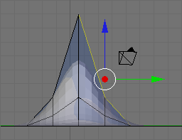
- Press Shift + E or Space → Edit → Edges → Crease SubSurf, then move the mouse away from the edge until the edge Crease reads 1.000 in the 3D viewport header. If moving the cursor there seems to be impossible, just hit 1 and enter.

As you move the cursor away from the edge you will notice two things. The first is that the edge becomes thicker as we move from it; this is showing how much of a crease we have (with Draw Creases turned on). The second is that you will notice the subsurfed mesh moving closer to the edge as the sharpness increases.
Naturalness
[edit | edit source]Press Ctrl + Tab to enter Edit Mode and select vertices. Then go into front view Num1 . Select the second vertex from the top in the centre of our Sharp Falloff mountain, then go into side view Num3 . Hold G and drag the vertex inwards, not too far or your mountain will come out of itself on the other side. Just bring it in enough to make a small indent.
Then grab the top vertex and pull it down a small amount. You will notice that there is a small "crunch" in your mountain.
Don't forget to select all with A , then W Shade Smooth button to smooth everything out.
OK, so your mountains are starting to shape up. But they still look a bit too neat. You could spend time moving each individual vertex but the chances are your model will still lack the natural feel. What we need is some chaos. Thankfully this is quite easy to accomplish. Firstly select the vertices that make up your mountains, all of them and a few around the base (box and circle select will make this easier). Select a few vertices between the mountains too. Next we use something called fractals. Fractals are chaotically (i.e. randomly) generated variables. In short you can use these variables to give your mountains a "wobbly" look.

In the Tools tab of the Tool Shelf, press Subdivide (under Mesh Tools), then look at the Subdivide submenu below. The value in the Fractal box is the strength of the fractal. 1 is very low and will barely change your model. 10 is very high and will twist your models into very odd shapes indeed. Have a play with different values until you find one that you like. Around about 4.0 should do it. Hit OK and presto, your mountains have been transformed from clinical neatness, to lumpy chaos.
- If you make too many fractals, your computer will slow down. However, the more you add, the more bumpy and realistic it looks!
Repeatedly using the fractal tool seems to rapidly multiply the amount of vertices on your canvas. I suggest using the tool once, and if the result isn't satisfying, undo the result ( Ctrl + Z ) and try it again with a different fractal strength. Helpfully, even after undo, your selected vertices remain selected.
Now go back into Object mode and view the result.
Modeling a Volcano
[edit | edit source]|
|
Applicable Blender version: 2.75. |
In this module, you will create a volcano using the proportional edit fall-off tool. You should be comfortable with deleting and adding meshes.
Adding a Plane
[edit | edit source]Delete the basic cube. Add a plane, and S cale it up by 10. Rotate it so you see it in top-view (make sure it's in Orthographic view too).
Enter Edit mode and subdivide (with W ) 5 or 6 times. More subdividing will give you a "smoother" volcano, but it also needs more CPU power.
"Subdivide" divides every square in the plane into four new squares. So every time you press "Subdivide" you will have four times as many squares as before. "Subidivide Multi" will make x horizontal and x vertical lines through your existing squares, so the new number of squares is: (squares_old)*(x+1)2, where x is the number you enter.
Making the Mountain
[edit | edit source]In top view, select one of the points in the middle of the plane. With this point selected change to side view. Press the O , which enables the "Proportional Edit Falloff" tool in the Menu-Panel beneath the 3-D-Window. As seen in the previous tutorial Blender 3D: Noob to Pro/Mountains Out Of Molehills when you move a vertex while edit falloff is enabled, all vertices in a defined radius of the selected vertex will align with the selected vertex when its position is altered. How they are adjusted can be chosen in the tab on the right of the yellow dot. I propose using "smooth falloff".

Now grab the vertex with G . You will now see a gray circle. You can change its size with the mouse wheel. Every vertex inside this radius will be affected by the falloff. Change the size of the circle so almost the whole plane is in it.

Now move the vertex a bit upwards, as seen in the picture. Optionally you can lock the z-axis to make the volcano go straight up by pressing Z .

As you can see all the other vertices will shift upward. We could keep moving this vertex at the same rate, but that would cause the plane itself to rise and bend, and that's not very good. So press LMB to apply the changes, grab the same vertex a second time and repeat the previous exercise as before, except now choose a smaller radius for the circle, about half the diameter of the plane ( G → Z → scroll MMB ).

Repeat this two or three more times and you will get something like this:

Forming the Crater
[edit | edit source]Now we're going to create the "hole" on the volcano. First change the falloff to "root". Grab the vertex one more time, change the size of the circle so it's more or less as seen in the picture.

Grab this vertex down a bit, apply, grab it one more time with a smaller circle. You now should have something like this:

Just leave the border jagged and just smooth (Subdivision Surface) the whole volcano cause it is much more realistic. Go to Object mode, select the volcano, go to the "Modifier" menu in the "Properties" Header and just click on "Add Modifier" -> Subdivision surface (you can leave "view" on 1). Do not apply these settings yet.

First we'll do a test-render. Still in "Object mode" Delete the default Lamp point with "X" or "Delete" and place your 3D cursor behind the camera and press Shift + A -> "Lamp" -> "Point". With the Lamp Point still selected Click on The Lamp point Properties ("Data") in the "Properties" Header then change "Energy" to "10". Press F12 to enter Render, after adjusting the camera.

Finishing the crater
[edit | edit source]You can very easily make a nice looking crater. Just go into "Edit Mode", touch "Num1". Make sure "limit selection to visible" is off and "proportional editing" is on and set it to "sharp" falloff. Select about the upper vertices with "border select" (Press "B key").

After that, scale (press "S key") it 'till it's a nice crater with a circle as large as mine.

And that's it, you just created a nicer looking crater.


Adding Magma
[edit | edit source]Let's add some "magma" using lighting.
- Make sure you're in "Object Mode"
- Press Shift + S and choose Cursor to Center.
- Press Shift + A and choose Lamp → Point.
- In the Properties window, click the Data tab.
- In the colour box (white by default) in the Lamp section, change the color to reddish-orange. (Red: 1, Green: 0.1, Blue: 0)
- Set the Energy to around 7.
- Raise the light until it's just above the bottom of the crater ( G rab along the Z axis).
- If the ground level of your plane is reflecting light from the lava lamp this is because the bottom of your crater is above ground level of the plane you created; you'll need to turn on ray-tracing. in the object data menu for the light, open the Shadow menu and click "Ray Shadow"
- Alternate 1: Spot Lamp
- Change the light's type to Spot.
- Raise the light until it's covering most of the crater. If the light is not pointing down, R otate and angle it downwards.You can also scale the radius of the light by press S to fit the rim of the crater.
- Alternate 2: Area Lamp
- Change the light's type to Area.
- R otate along the Y axis: 180 degrees.
- Set Gamma to 2.
- Set Distance to around 5.
Experiment with the values and positioning to get something that works with your volcano.
It should now look like this:

Varying the Terrain
[edit | edit source]Next, let's set the volcano's material.
- RMB on the volcano plane.
- Select the "Material" button and press New.
- Change the Diffuse color to ashen gray. (Red: 0.260, Green: 0.230, Blue: 0.230)
- Select the "Texture" button and press New.
- Change the Type to Stucci.
- In the Influence panel, uncheck Color, and check Normal. Set the Normal slider to 0.5. This will render the texture as a bump-map.
(Note: In version 2.77 you may need to change the texture Mapping -> Coordinates option from UV to Generated before you see bumps appear.)
(Note: In version 2.78c you may need to change the texture Mapping -> Coordinates option from UV to Global or Object before you see bumps appear.)
Older versions:
Select the volcano and press F5. Keep Pressing F5 until the Materials Buttons (symbolized by a red ball) is highlighted. Then add a new material. You do this by clicking the Add New button in the Links and Pipeline Panel. Once you've done that, set the settings similar to the picture below. Now press F6, then add a new texture to the material. Choose a stucci texture, set the noise size to 0.15. Now switch back to the materials-window (F5) and click on the "map to" tab. Deselect the "col" button and select the "nor" button. This will render the texture as a bump-map on the volcano. Set the "nor slider" to 0.5, which should be the default. Switch to the "map input" tab and choose "tube".

If you now render you should get something like this:

This looks really smooth, like clay pottery. To get a more rough-looking volcano, try out these options:
- Option 1: Subdivide and increase the fractal. 5 should do the trick.

- Option 2: Decrease the texture's basis size (in the "Stucci" panel when you select the "Texture" button).
- Option 3: Proportional edit tool.
- Press O to turn on Proportional Editing mode. Select Random fallout.
- G rab the center vertex, and raise it along the Z axis.
Older versions:
Go into Edit mode, select all Vertices, and use the fractal (set from 15 to 30) to really get things looking rocky and mountainous. TAB (Edit mode) → F9 → AKEY to select all → Mesh Tools → Fractal → 15 - 30 (15-low, 30-high) → OK → TAB (Object mode) In Blender 2.5 you can use the random proportional edit tool: use NUM7 to switch into top view, grab the central vertex of your volcano using a large-radius random proportional edit, and pull it slightly into Z-direction.
(A note: Seems there is no need in subsurf at all since fractal tool will dramatically increase vertex quantity.)
Penguins from Spheres
[edit | edit source]|
|
Applicable Blender version: 2.75. |
Note: Some Pictures are outdated.
Setup
[edit | edit source]Start with the default scene: it should contain a selected cube. Delete this cube by pressing X → Delete.

Put the 3D cursor at the scene center by pressing Shift + C .
- Note: after deleting the cube you must be in Object Mode. If not, Press CTRL-Z and switch with TAB and redo the operation.
Creating the body
[edit | edit source]
Noob note: to ensure that you don't become confused, make sure that your viewport is set up in the same direction you see in these pictures. The colored arrows are red, green, and blue and they control the x, y, and z axes, respectively.)
- We start by creating our main body from a sphere. Press SHIFT + A → Mesh → UVSphere, then choose 16 segments and 16 rings.
We're going to make it look like a penguin body:
- Press TAB to enter Edit mode
- press NUM1 to switch to the front view,
- with all the vertices selected (if not, A ), choose the scale tool ( S ),
- restrict scaling to the Z-axis ( Z ),
- and move the mouse away from the 3D cursor while holding down the CTRL key (this snaps the scale values to whole numbers),
- Note: Make sure the mouse cursor is not too far away from the sphere when hitting the S or else you may not be able to reach a 2.000 scale value. The scaling steps are proportional to the distance from the 3D cursor when calling the scale tool.
- the current scale shows in the lower left corner of the viewport, click when you've reached 2.000 LMB ).
- Note: You can also do this by typing in 2 after starting the scale and restricting movement to the Z-axis: S -> Z -> 2
This is our main body!
Shaping the head
[edit | edit source]We’re going to shape the penguin head from the top of the sphere.

Start by selecting the top-most single vertex as well as the top two smallest circle segments.
- Note: Selection has been explained in a previous tutorial. Here, the easiest methods are either box selection B ) in the front view NUM1 ) and Limit selection to visible off, or lasso selection ( CTRL + LMB ) in the top view ( NUM7 ) and Limit selection to visible on. You can also switch to top view, center your mouse on the topmost vertex and use the circle tool. Don't forget to deselect all first ( A )
- Noob note: You can also select the top vertex and press CTRL + NUM+ twice to select the circle segments.
- Noob note: Make sure the Limit selection to visible/Occlude background geometry button is in the right state each time you select vertices, edges or faces. When it's off, selection affects any item, visible or not.
Building the neck with the 3D transform manipulators
[edit | edit source]To turn on the 3D transform manipulator, either push down its button ![]() or use CTRL + SPACE and choose Enable/Disable.
or use CTRL + SPACE and choose Enable/Disable.
Moving the two selected circles up
[edit | edit source]
Go to the front view ( NUM1 ). Drag the blue arrow while holding the CTRL key down to move the selected vertices 0.3 units up.
- Noob note: you may not be able to snap the extrusion lengths to tenths of units. CTRL snaps to the grid size by default: if you can only translate by one unit (1.0), zoom in until the grid divides itself into tenths (SCROLL). Some Blender versions allow to snap to one tenth of the current step by holding both the SHIFT and CTRL keys while moving the mouse.
- Noob note: instead of the Transform manipulator, you can use the G and constraint the movement to the Z axis ( Z ).
Rotating the neck
[edit | edit source]
Now switch to the side view ( NUM3 ) and make sure that the rotation/pivot point is set to "median point" either by selecting it from the third drop down menu right of the "Mesh" menu, or by pressing CTRL + , . Choose the Rotate tool ( R ). Move the mouse with the CTRL key down to rotate the selection 30 degrees counter-clockwise. Use LMB to validate the rotation.

Select an additional ring of vertices by expanding the selection ( CTRL + NUM+ (Note: NUM+ Refers to the addition symbol on the NUM Pad, KEY+ will not do.). You can contract the selection by pressing CTRL + NUM− . Move these vertices an additional 0.3 units up, then rotate them as previously 30 degrees counter-clockwise in the side view.

Repeat those steps (selection expansion, translation and rotation) two more times and you'll end up with the body seen in the below.
That doesn’t really look like a penguin, yet!

Now move all of the selected vertices to the left 0.4 units by pulling the manipulator's green arrow (and of course holding the CTRL key down). This straightens out the neck as seen in the next picture.
- Noob note: you can also use the G and translate the selection by -0.4 as displayed in the bottom left corner of the viewport. Still do this in the side view ( NUM3 ).
- Noob note if you had to pull the red arrow, not the green one, then you probably didn't switch to side view, and modeled the neck in front view. If you realize here that you have this done from another view then press AKEY twice, then NUM7, then Space -> Transform -> Rotate and type 90 or 270
Creating the beak
[edit | edit source]
Switch to the front view ( NUM1 ), and select the frontmost vertex (the one that originally was the top vertex of the sphere) with the RMB . Then switch to the side view ( NUM3 ) and translate this vertex to the left by 1.2 units using the manipulator's green arrow or the translate tool.
- Note: some Blender versions allow moving the vertices from the keyboard with the following sequence: G , Y , -1.2, ENTER .
The main body of the penguin is now finished. The next step is to create some flappers for the poor little guy.
Extruding the wings
[edit | edit source]We are going to create the wings by extruding faces on each side of the penguin.
- Noob Note: You can rotate the whole object by pressing A to select all of its vertex and then rotate it pressing R or using the Rotate Manipulator until the axis on your screen matches the axis on the example image. That way, also, you can practice a little more.

Choose the side view ( NUM3 ) and switch to the Face select mode ( CTRL + TAB → Faces, or click on the orange-sided cube icon in the toolbar).

Now, select two faces that will make up the penguin’s shoulder as shown on the right (either select the first one with RMB and the second one holding SHIFT , or use box selection ( B ) to select them both in a single operation).

Then switch to front view ( NUM1 ) and extrude the selection:
- choose E → Region,
- constrain to the X axis ( X ),
- hold CTRL to snap,
- and move the mouse to extrude the shoulder by 0.2 to 0.3 units.

We'll now extrude the bottom face of this new extrusion. Rotate the view to show it with:
- a MMB drag,
- or several presses on NUM2 ,
- or CTRL + NUM7 (bottom view).
Press the A to deselect all, and select the bottom face ( RMB ), switch to front view ( NUM1 ), extrude by 1.4 units down ( E and CTRL ).
Now do the same on the penguin's other side: use CTRL + NUM3 to view the left side (you can also rotate with MMB , or press NUM4 several times).
Smoothing the wings
[edit | edit source]We’re going to smooth out the shoulders and improve the wings. Though this can be done in many ways, we'll only use the merge tool.

Rotate your penguin so that you can see one shoulder from above. Then switch to Vertex select mode ( CTRL + TAB → Vertices). Press A to deselect all, then select the two shoulder vertices with RMB and SHIFT .
Press ALT + M , choose At Center from the popup in order to merge the two vertices at their center. Finally dismiss the message saying Removed 1 Vertices.

Repeat the steps with the two other vertex pairs shown on the right picture, and smooth the other wing. I’m leaving the middle segments for now, else the wing tips will be too pointy.
- Note: if you have troubles merging vertices, it comes from vertex duplicates in your mesh. You probably chose Individual Faces instead of Region when extruding the wings, which creates duplicate vertices and neighbouring faces. To clean up your model: select all vertices ( A ) and choose W → Remove Doubles.
You must do them one by one!
Or, Alternatively, change into Edge select mode ( CTRL + TAB → Edge), select the edges to smooth ( CTRL + LMB ), press ALT + M , choose Collapse

Finish off the wings by selecting the two backmost vertices of the wings, and moving them up using the blue arrow by 0.1 unit.

You should now have something like this:
Cutting the underside
[edit | edit source]

We're going to cut the penguin's lower end, for it to stand up! Select the bottom vertices (bottom vertex and the first ring above it) as shown in the picture. There are many ways, this is left as an exercise.
Once they're selected, delete them ( X → Vertices). Now our penguin is hollow: select all the vertices around the hole, and fill it using ALT + F .
- Noob note: To quickly select all the vertices around the hole, you can enter edge mode CTRL + TAB -> "Edges", and then select one edge that goes around the hole. Now press CTRL+E -> "Edge Loop Select", which should select all edges around the hole. Now go back to Vertex select mode and continue with ALT + F .
- Noob note: For Blender 2.56 In vertex select mode and occlude on hold down ALT and select one of the vertices all the vertices in the ring will be selected.
Adding the feet
[edit | edit source]
The next step is to provide the little guy with feet. To do this, we’re going to extrude two of the front faces:
- choose the front view ( NUM1 ),
- switch to Face select mode,
- turn on Limit selection to visible,
- and select the face to the left and right of the middle two faces of the penguin.

Then switch to the side view ( NUM3 ) and extrude the selection by -0.6 units ( E → Region, restrict to the Y axis: Y ).

Keep the selection and look for the Mesh Tools in the Tool Shelf. If you can’t see it, press T to make the Tool Shelf visible. Then click on the Subdivide button (under Add in the Tools tab). Or press W and choose Subdivide.

Switch to "Vertex Select Mode", Now select the three middle vertices (or two edges) vertically at the tip of each foot, and drag them along the Y axis by 0.3 units towards the penguin
- Note: if something goes wrong here, you may need to remove double first. As always, to move the vertices, either use the manipulator or G and Y sequence.

You should end up with what's shown in the right picture (minus the selection).

The feet look too thick, let's flatten them a bit. Switch to the front view ( NUM1 ) and select the two bottom vertex rows (Limit selection to visible off, use either the lasso or box selection).

Then choose the scale tool ( S ), limit its action to the Z axis ( Z ) and scale down by a factor of 0.4.
The feet still look rather peculiar, so please go ahead and move the vertices around on your own as you like.
Reminder: you can use the G and restrict movements to the X or Y axis using the X or Y . Try not to move vertices along the Z axis to keep the penguin's bottom flat.
Extruding a tail
[edit | edit source]


To complete the penguin, we have to add a tail (the end of the tuxedo):
- go to the back view ( CTRL + NUM1 ),
- make sure you're still in Vertex select mode,
- and that Limit selection to visible/Occlude background geometry is on.
Select the three middle vertices in the second row up from the bottom. Then, switch to the side view ( NUM3 ) and extrude the edges 0.3 units away from the penguin and 0.08 units down ( E → Edges), so that the end of the tail is at the same level as the bottom of the penguin.
Noob Note: Or you can extrude the edges 0.3 units away from the penguin, then G Z -0.08, LMB or ENTER .
Press CTRL + S to save your work!
Subsurfing
[edit | edit source]
Go to Object Mode ( TAB ), and make sure the penguin is selected. Then check for the Modifiers toolkit in the Buttons panel. Press Add Modifier → Subsurf (or Press SHIFT + O ).
Look at the penguin now, he’s much smoother. You can alter the levels of the subsurfing if you like, but I’ll settle for level one. Under the Links and Materials toolkit, you can press the Set Smooth button as well, which makes the penguin really slick.
- Note: you may see some weird effects at the bottom and the tail after subsurfing the penguin. If so, there is an issue with normals: they have to be all pointing outwards. This can be achieved by selecting all vertices in Edit Mode and recalculating the normals outside ( CTRL + N ). Click on the message to confirm. Note that CTRL + SHIFT + N will turn the normals inwards and that W → Flip Normals flips them.
- Question: The finished penguin looks fine in Object Mode, but when I render it, it looks odd. Quite patchy.
- Answer: Make sure you adjust the "Render Levels" parameter (directly under "Levels") to be greater-or-equal than "Levels".
Extra
[edit | edit source]The penguin can be colored or textured, but that will be part of later tutorials!
-
 This is what the penguin (sans tail) looks like, textured and ready. Orbisonitrum
 -
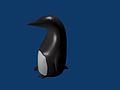 The eyes are there, just not easily visible in the thumb. At the top of the white part, two faces on the chest were subdivided to give the white more of a curve at the top. The faces were selected that were going to be white, and the I used separate (P) to make them a different mesh. I used a white material for the chest, black for the body, and grey uvspheres for the eyes. Apparently, an easier way to colour the chest can be found at Multiple Materialsplease feel free to replace this with your own image of the penguin you made, with comments on how you put your own style into it
 -
 A pretty basic picture of a penguin. I subdivided the stomach and eyes, but then I also added some eyeballs by making a UVSphere, cutting the top of it off, and then placing it inside of my penguin's head. All the colors have specular colors, giving the penguin a slight blue glow under the black.


Dicing With Depth (Dice Modeling)
[edit | edit source]|
|
Applicable Blender version: 2.67. |

Dice are objects which are familiar to us all, used in countless games. Here we will model how to make a single die (or a single dice, if you prefer).
The end result should look something like at right. Notice the following features:
- different colours for the pips versus the body of the die
- rounded edges and corners, while the faces are (mostly) flat
- round, recessed pips.
Achieving all these effects will be a good exercise of your mesh-modelling skills.
Characteristics of the Die
[edit | edit source]
The number of pips on each face of a die ranges from 1 to 6. However, in order to space them correctly, there needs to be 9 positions for a pip on each face, even though not all of them will be filled on any face.

We will also proportion our die so that the diameter of each pip will be twice the horizontal or vertical distance between pips, even though if you look at the illustration the pips on the finished die look smaller because they eventually do not occupy this full diameter. As you will see, this makes it easy to get the proportions uniform with a relatively small number of loop cuts.

Also note one of the characteristics of real dice is that the number of pips on opposite sides adds up to 7 as depicted in the Standard Die Layout.
The Basic Mesh
[edit | edit source]Open a new Blender document. Select RMB the default cube, and TAB into Edit mode.

First of all, let’s apply a small amount of bevel to the corners and edges: with all the vertices selected, press CTRL + B to start bevelling—not too much, press LMB when you see something like at right.

Now, we need to make a bunch of loop cuts to mark out the areas where the pips will go. To simplify things, we will do cuts through the middle of each pip, as well as between pips—a total of 9 loops each way—then go back and remove the unneeded cuts. That way we get the 2:1 proportions correct with a minimum of effort. Who says it doesn’t pay to plan ahead?
To make a loop cut, press CTRL + R , then move the cursor over the edge you wish to subdivide: you should see a single magenta loop appear. Now press 9KEY , and you should see this change to 9 loops. Next, click LMB to change the lines to yellow and really start cutting, then immediately press RMB to finish the cut without moving the cuts from their initial positions.
You will need to do this 3 times, between the 3 pairs of opposing faces.


Now look at each face of your cube: you will see an 11×11 grid of vertices, with the corner vertices each adjoining a triangle at the corner. Make sure nothing is initially selected. Count the third vertex in from a corner, and move the mouse slightly so it is over the edge leading from this vertex into the interior of the face, just to avoid confusion; now Shift + ALT + RMB , and you should select a loop like at right.
If you get the wrong selection, just A to clear it, and try again. Remember to click over an edge that is running the right way, rather than a vertex, otherwise Blender is liable to select a loop running the wrong way.
Press DEL or X , and in the deletion menu that appears, select “Edge Loops”. The selected loop should disappear.


Going in from the edge of the face, skip over one loop, and remove the middle one.

Then finally remove the third one in from the opposite edge.

You need to do this deletion of loops on every face that has the original 11 X 11 grid of vertices. When you are finished, the resulting mesh should look like at right.
Making the Pips
[edit | edit source]
Now we will hollow out the spots or pips. The idea is to extrude selected ones of the large squares on each face inwards into the cube (“intrude” rather than “extrude”, perhaps?), then split the bottom of each resulting pit into four triangles each by adding an extra vertex in the middle; then pushing in this vertex will give us the hollow for the pip (as at right).
We will show three methods for doing this.
Do this individually for each face that is to be made into a pip.
Method 1 (Slowest)
[edit | edit source]Select all the large squares to be made into pips (perhaps do one entire face at a time). Press CTRL + T to triangulate these faces. Now switch to edge-select mode, and select the new diagonal edge that has appeared in the middle of the original squares; bring up CTRL + E for edge Specials and select Subdivide (leave the number of subdivisions at the default 1). Things won’t look any different, but each triangle is now a quad, with an extra vertex added to the middle of each of those diagonals.
Now switch back to face-select mode, select those subdivided halves of all the squares, and CTRL + T to triangulate again.
Method 2 (Faster)
[edit | edit source]Switch to face-select mode. Select all the large squares to be made into pips (perhaps do one entire face at a time). Do E to extrude, and immediately press ESC to leave the new extruded vertices in the same positions as the old ones; now do ALT + M to merge and select the “Collapse” option.
Method 3 (Fastest)
[edit | edit source]Select the relevant large squares on each side to make the required numbers for each face of a real die. From CTRL + F for face Specials, select “Poke Faces” (or more directly, do ALT + P ). Leave the settings at their defaults (in particular, leave the Poke Offset at 0).
Digging The Holes
[edit | edit source]Now that you have crossed the faces of your pips, select the middle vertices one side at a time, and G rab inwards by a distance of 0.17 (make sure you do it at the appropriate axis, pres Z , X , Y ) along the appropriate axis.
Noob Note: Do this side after side, otherwise you will translate all your vertices to one side and not all inside.
Rounding Things Off
[edit | edit source]
Now apply a subsurf modifier and set the shading to smooth, the result should look something like this.
The trouble is, the pips look too much like dimples rather than proper holes. To fix this, we can apply a crease to sharpen up the edges.

In edge-select mode, select the four edges around the opening of each pip. Press SHIFT + E , and move the mouse until the edges take on the darkest magenta tint. That should firm up the edges of the holes a bit.
Colouring Your Die
[edit | edit source]First, go to the Materials Context ![]() and set up the colour for the main part of the die (say, make it red as in the illustration above). This can be done in Object or Edit modes.
and set up the colour for the main part of the die (say, make it red as in the illustration above). This can be done in Object or Edit modes.
Next, click the “+” button to add a second, initially empty, material slot, then click the “+New” button that appears below it to create a new material for this slot. Make this material white, for the pips. Then, select the pips themselves, and use the “Assign” button to colour them with this material as detailed below.
Quickly Selecting The Pips, Method 1
[edit | edit source]Go to the Select menu, and select the option “Select Faces by Sides”. A panel will appear at the bottom of the Tool Shelf (use T to toggle the visibility of this), with a field titled “Number of Vertices”, initially showing 4; change this to 3, and it should select all the triangles, which includes the pips as well as the corners of the cube. You can deselect the latter one by one by SHIFT + RMB ing them.
Quickly Selecting The Pips, Method 2
[edit | edit source]Alternatively, you can do just select the faces of each pip.
Quickly Selecting The Pips, Method 3 (Fastest)
[edit | edit source](Works in blender 2.6, not sure about earlier versions.) In face select mode select one of the triangular faces of one of the pips. Hit space and type "select similar" then choose "area." If this selects too many faces along the edge of the die, cancel and try again with "perimeter."
Model a Goblet
[edit | edit source]|
|
Applicable Blender version: 2.75. |
Why a goblet? After all, goblets (fancy containers for consumable liquids) are not really all that important in the real world. However, they represent a very large class of interesting objects: those that are radially symmetric. Also, they are fun to play with.
To model a goblet and actually see the result, we do the following steps:
- create the actual mesh of the object.
- apply a material to the object.
- create and light a scene to display the goblet
- render the scene.
The following tutorials demonstrate three different approaches to creating the mesh model, and then show two different materials (glass and silver) that may be applied to the goblet. Finally, we add the minimal elements to the scene to permit an "interesting" rendering.
Three ways to build the mesh
[edit | edit source]As a beginner, you may wonder why we describe three different ways to build the mesh. After all, surely the Pros know of a "best" method?! The answer is that there is not really a best method. Blender provides a sophisticated toolkit, and different blender artists will become familiar with different tools. If, after you gain experience, you become comfortable with cube extrusion, then this may become your preferred tool. If you need more than four vertices per "circle" you may find that cylinder extrusion is better for some particular object. If you are comfortable with "spinning" an object, then spinning may be right for you. All three techniques generate an object that is defined by a set of vertices on a set of circles that are "stacked" on a common axis.
After we build the mesh using one of the three methods, we can apply any number of fancy techniques for texture and rendering. We provide two simple "cookbook" approaches in this section so you can see the result, but materials are treated much more extensively in other sections of the book.
In the next three sections of the book we describe the "cube extrusion" approach, the "cylinder" approach, and the "spin" approach. Following sections describe three textures that can be applied to objects that are created with any of the approaches, and the final tutorial provides a simple way to render the result.
The "cube extrusion" approach is a basic technique that all blender artists will become familiar with, to model most types of objects. Since it is such a basic technique, it may become the most efficient way for you to create objects, and you may choose to use it wherever possible rather than switching to a less familiar technique. You can see from the tutorial that this technique is perfectly acceptable for goblets, and by extension it will work for similar objects.
You may prefer the "cylinder extrusion" technique when you need more than four vertices per circle, because cylinder extrusion is very similar to cube extrusion. Thus your proficiency with cube extrusion will directly carry over to cylinder extrusion.
"Spinning" is conceptually different, even though it creates the same mesh as cylinder extrusion. Spinning is the easiest way to create a radially symmetric model from a two-dimensional description of the cross-section of an object.
How many circles?
[edit | edit source]

Each of the three methods defines a set of stacked circles, with vertices equidistant around each circle. The "cube extrusion" technique has four vertices on each circle, while the cylinder and spin techniques have a user-specified number of vertices per circle. But how did we pick the number of circles and the spacing between them?
The answer is that we know in advance that we intend to use a technique called "subsurf". Subsurf interpolates additional vertices between those we explicitly specify, and this "smooths out" the profile of our goblet.
This will cause problems where we need a fairly sharp "bend" in the profile, as between the base and the stem and between the stem and the "bulb" of the goblet. At each point in the profile that has a (fairly) sharp bend, we need for the vertical circles to be close to each other. The two images illustrate this effect. Each image shows an outline of the object, the spun object, and the result after subsurf (level 2) has been applied. The outlines and the spun images are nearly identical, but the subsurfed result is very different, because there are three extra vertices in the second outline: one just above the bottom of the base, one at the top of the base, and one below the bulb: these are the three locations where we need relatively sharp changes in contour. When we spin the outline, the first outline generates seven circles and two degenerate circles, while the second outline generates ten circles and two degenerate circles. Those extra three circles make all the difference. The same phenomenon occurs with the other two modelling techniques.
Model a Silver Goblet
[edit | edit source]|
|
Applicable Blender version: 2.75. |
Basic Shape
[edit | edit source]
At first glance, the goblet looks like it is composed of cylinders. However, while it is possible to model the goblet with a cylinder mesh, it is easier to make a goblet by using cubes. Cubes make the goblet faster to make and it makes fewer vertices to track. Now, lets start making the basic shape of the goblet.
Start with the default cube and go to Edit Mode ( TAB ). Toggle off "limit selection to visible". Move to the side view ( NUM3 ). Toggle to ortho view. Box select ( B ) the top edges of the cube. Extrude ( E ) upward about one grid square. Hold down CTRL while extruding for incremental movement; by default movement should be restricted to the Z-axis (normal to the selection); if necessary, press Z to toggle this effect. This extrusion is called E1. Repeat 2 more times for extrusion 2 and 3 (E2 and E3).
Now Extrude a longer piece upwards, for the Goblet's stem, of 10 grid squares (E4). Next we will define the area for the 2 top knobs and the bottom of the glass by Extruding upwards 5 more times at 1 grid square each (E5-E9). Next do another upward Extrusion of about 10 grid squares (E10). This is the actual glass itself.
Inflate the Glass
[edit | edit source]
Now, let's begin to inflate the glass. First, clear all selections by hitting the A . Make sure you are still in the side view ( NUM3 ). Box select ( B ) the bottom most cube (all 8 vertices, not just the bottom 4). Then expand it outward by scaling ( S ), then pressing SHIFT + Z to lock/prevent any scaling in height along the Z-axis and finally pressing 4 to quadruple its size. Next, deselect all vertices ( A ), select ( B ) the 4th pair of vertices (E2), scale them ( S ), lock scaling ( SHIFT + Z ) and triple the vertices in size ( S and 3 ).
Do the same for E5 and E7 (the 7th and 9th pairs of vertices, respectively). Then expand ( S and SHIFT + Z ) the top, Goblet rectangle (E9 and E10) to 6 times its current size ( 6 ).
Make the cup's interior
[edit | edit source]

Last is the cup's interior. Once again, you should still be in the side view ( NUM3 ). Box select ( B ) the very top most vertices of the Goblet (E10). Once selected, get a better view by changing to 'Orbit Up' ( NUM8 ). With the top surface selected, initiate an Extrusion ( E ), followed by a termination with the ESCAPE . It will appear as if nothing has happened, but new, overlapping edges have been created and are now selected (this also creates E11). Next Scale ( S ) the selected vertices to 90% of the original size ( .9 ). This creates the inside lip of the cup. Now, Extrude ( E ) the interior lip, along the Z-axis downward ( -10 ) to create the bottom interior of the Goblet (E12). Finish off by selecting all, and then a 'Remove Doubles' ( W → Remove Doubles), for good measure. It should look something like this.
Smoothing and Defining
[edit | edit source]Time to take the mesh and turn it into a proper goblet. Add a subsurf modifier with 3 view subdivisions to the mesh. Change to Object Mode ( TAB ) and select smooth shading. The cube-looking mesh will now look like an object that was created from a cylinder. This has removed all our crisp edges, but our globlet is looking very unstable! Let's rectify things by flattening the bottom.
Noob Note: If your goblet has a bulge in it after applying the subsurf, go to Edit mode ( Tab ), select all ( A ), press W , and select "Remove doubles". (If a menu for boolean operations appears when you hit the W , then you're not in Edit mode; change immediately to Edit mode and try the W again.)
Select the four edges that surround the small circle at the very bottom (the very lowest set of edges) and press SHIFT + E to enable creasing. Now drag the mouse up and down to select the level of the crease. When you're satisfied, hit LMB . Repeat the process for other edges you want to be sharp. I've turned on Draw Creases under Mesh Tools 1 to illustrate which edges have been creased (highlighted yellow) in this example.
That concludes the creation of the goblet. Save the scene for use in the lighting tutorial.


Quick links for the impatient
[edit | edit source]To jump to the relevant lighting section, go to Blender 3D: Noob to Pro/Light a Silver Goblet.
What about applying glass look already? Take a sneak peek at Blender 3D: Noob to Pro/Spin a goblet#Material.
Model a Silver Goblet Another Way
[edit | edit source]|
|
Applicable Blender version: 2.75. |
Preliminaries
[edit | edit source]This is a version of "Model a Silver Goblet" but starting from a cylinder rather than a cube.
Start Blender or start a new scene ( Ctrl + X ) and delete the default cube.
Change to Top view ( Num7 ), make sure you're in Object mode and add a cylinder ( Shift + A Mesh > Cylinder): in the popup menu, change the number of vertices from 32 to 16, the Radius from 1.000 to 1.800, the Depth from 2.000 to 0.100 and leave "Cap Ends" as it is.
Change to Front view ( Num1 ).
Description of the modeling steps
[edit | edit source]The steps in this tutorial are almost all made up of "extrude" and "scale": so, to avoid repeating key sequences every time,
- extrude
- means
- make sure "Limit selection to visible" is off

Shows "Limit selection to visible" icon - box select the top vertices of the cylinder: press B , click and drag LMB to make a rectangle around the top vertices
- press E , press Z and type in the amount of the extrusion and press Enter ; you can move the mouse instead but it is quicker and easier to type it in.

For example, the following keystroke sequence extrudes by 1.5:
B , click and drag LMB to make a rectangle around the top vertices; E Z 1 . 5 Enter .
- scale
- scaling is by default restricted to the X-Y plane; although the numbers in the bottom left corner of the 3Dview show Z changing, in fact only X and Y change, and by equal amounts.
- press S , type in the value and press enter — you can use the mouse instead but it is quicker and easier to type in the number.
Creating the Goblet
[edit | edit source]
This diagram shows the connection between the E-numbers and the goblet construction.
- E1: Deselect all vertices ( A ), Box-select the top vertices (B-key), and extrude by 0.2: you may need to zoom in ( SCROLL ) to do this as it's quite thin. Scale to 0.1.
- E2: Extrude by 0.2, scale by 2.
- E3: Extrude by 0.2, scale by 0.5 to make the lower knob.
- E4: Extrude by 4 to make the stem.
- E5: Extrude by 0.2, scale by 2.
- E6: Extrude by 0.2, scale by 0.5 to make the upper knob.
- E7: Extrude by 0.2, scale by 8 to make the base of the cup.
- E8: Extrude by 4, if you wish to make a flared cup, you can scale by 1.5.
- E9: Extrude by 0.0, scale by 0.9 to make the rim of the cup. (This will create a new ring of vertices and then move them in towards the centre.)
- Now go into Wireframe mode ( Z ) so you can see inside to guide the next few steps.
- E10: Extrude by -3.9, that is, downwards. and scale by 0.69: you can do this last scaling with the mouse, if you like, to get the edges of the inside of the cup and the outside parallel.
- E11: Extrude by 0.0, scale by 0.0 to make the inside of the cup. Press W Remove Doubles to merge the centre vertexes.
You now have a goblet, the base of the inside of the cup is the face of the last extrusion, is circular and flat as it derives from a cylinder.
If you haven't already saved your work-in-progress, now would be a good time.
Subsurfing and smoothing the goblet
[edit | edit source]The last step is to subsurf and smooth: go into Object mode and enable Solid mode again ( Z ).
Select the Editing panel from the Buttons window ( F9 ) and, in the "Modifiers" panel, click on "Add Modifier", select "Subdivision Surface" from the popup menu and, in the Subsurf display, increase "View subdivisions" from 1 to 2.

At the bottom right of the "Links and Materials" panel, click on the "Shading: Smooth" button. At the bottom of the cup you will see fluting — this is an artifact caused by smoothing and subsurfing triangles on a curved surface. Here it adds to the appearance, don't you think?
In Blender v2.78, the "Smooth" button is located in the "Tools" menu under the "Edit" tab.

Flattening the base of the goblet
[edit | edit source]The base of the goblet is curved due to the subsurfing, so needs to be flattened.
Go into Edit mode, deselect all, box-select the lowest set of vertices, then crease (remove the subsurfing) by pressing Shift + E then 1 enter .
The final result should look something like this:


Save the scene for use in the lighting tutorial. To jump to the relevant lighting section, go to Blender 3D: Noob to Pro/Light a Silver Goblet
Spin a goblet
[edit | edit source]|
|
Applicable Blender version: 2.66. |
The spin technique is a good choice when you want to model an object that is radially symmetric and you know what the cross section of the object looks like. This the virtual equivalent of using a lathe to create an object in the real world. With the spin technique, we draw an outline of one half of the outline of the object, and then spin the outline about an axis to create the object's mesh.
Modeling
[edit | edit source]
Here is a real-world goblet. The picture is not an orthographic image, so we cannot directly copy the outline, but it is close.
Setup
[edit | edit source]We now model the outline. Let's start with the default model. We want to create an initial object consisting of a two-dimensional outline, so select the cube, go to edit mode, and delete all the vertices. This leaves us with an object that has no vertices as a nice place to start. We want the resulting goblet to sit at the origin with the Z axis as its axis of symmetry so we get a front view (press NUM1 ). Since we will be working directly with mesh vertices, the manipulator is a hindrance, so turn it off (press Ctrl + Space ). (With the manipulator on, it is easy to accidentally move a vertex out of the editing plane, but we want a 2D cross-section.) We are now ready to create the two-dimensional outline as a chain of vertices with the first and last vertices on the axis.
First Vertex
[edit | edit source]Now, place the first vertex: this will be the center of the bottom of the goblet, so place it slightly above the origin on the Z axis ( Ctrl + LMB ). Why? Well, for two reasons: in the real world, the bottom of a goblet is not actually flat. Instead, the rim is lower than the center of the bottom, so the bottom is concave and the goblet sits on a flat surface without wobbling. The second reason is that we intend to use the "subsurf" technique, and this technique will make a flat surface slightly convex in our virtual world, so we will preemptively start the bottom of the base with a slightly concave surface.
Finish the outline
[edit | edit source]Add the second vertex, which will be on the rim of the goblet's base: move the cursor to the X axis at about -3, and add a vertex (press Ctrl + LMB , or E , Enter ). Add additional vertices to your outline by moving the cursor to the desired location and adding,[1] for as many vertices as you need to accurately model the outline. Since you will be using subsurf later, make sure that you place two vertices near each other when you need a sharp curve in your outline. Otherwise, subsurf will convert your sharp curve into a wide smooth curve.
Eventually, you will place the last vertex, which will become the point at the bottom of the inside of the goblet. This point should be on the Z axis. Your outline is done!
Spin
[edit | edit source]Now, to spin it. first, make sure that you are still in edit mode, and that the last vertex is selected. Set the cursor to the selection ( Shift + S , then cursor→selection). Now, get a top view ( NUM7 ): you are now looking at your outline from the top, and it should look like a straight line along the X axis with one end at the cursor on the Z axis. (If this is not the case, select and move points to the X axis and check your work by switching back to the front view, then come back to the top view.) Now select the whole outline and then move to the button menu to perform the spin (or use the Spin option under Mesh Tools, Add, in the Toolshelf). Set the rotation to 360 and the steps to 12 (or another number of your choice)." An elaborate circle will appear. Go to the front view ( NUM1 ) to see your un-smooth goblet.
Finish up
[edit | edit source]Since you are in edit mode and you have the whole mesh selected, this is a good time to remove duplicate vertices. The two vertices on the Z axis (base bottom center and bulb bottom center) were duplicated 12 times, and the entire outline was duplicated once when the circle closed at the end of the spin. Remove the duplicates (press W and select Remove Doubles). If you fail to do this, the subsurf operation will create a cusp at the two centers, and a crease at the duplicated outline.
If you placed the two Z-axis vertices by hand, they may not be exactly on the axis, and therefore may still be duplicated, leaving a tiny "hole" at the axis. Fix this by merging each of the two sets separately:
- select the vertices to merge.
- merge at center (press W ,Merge → At Center, Enter ).
Now start to smooth by using the subsurf in the button window. First add a modifier and select subsurf. Set levels to 2 Then, click on smooth in the Tool shelf under "Tools" -> "Shading". You now have a goblet model.

The image shows four objects: the two-dimensional outline, a smoothed version of the two-dimensional outline, the result of spinning the outline, and the result of subsurfing and smoothing. As you follow the procedure above, you will not actually have more than one object at a time as shown here.
Rendering
[edit | edit source]
As with the other two goblets, It is difficult to fully evaluate the model unless you render it. However, a "pretty" rendering requires at least minimal materials, lighting, and scenery. This section is a cookbook approach to providing these minimal elements and is not really a useful tutorial, so we won't explain the concepts. These topics are treated at length in later tutorials. If you wish to explore these subjects in more depth, go to the appropriate tutorials.
- The Goblet material: plain glass.
- The tablecloth: A (non-existent) table with a white tablecloth, in a featureless room painted yellow.
- The lighting: one bright lamp.
Material
[edit | edit source]- Go to object mode and select the goblet.
- In the Materials button window, add a material to the goblet, and name it "glass".
- In the Material tab, change the color in Diffuse section to black (set R, G, and B all to 0.000). Here, "black" merely means "do not add any color". It does not mean that the goblet looks black.
- In Transparency section, pick Raytrace. Set Alpha to 0.1 (i.e., quite transparent), set IOR to 1.5, and set Depth to 6 (or higher on a very fast computer).
Tablecloth and room
[edit | edit source]- In the main window, put the cursor at the origin (Center) and switch to top view. In object mode, add a plane and then scale it to quite large. This is your tablecloth
- Go to object mode and select the tablecloth.
- In the Material tab, set the color to white and ensure the Alpha is 1.000 (i.e., opaque.)
- In the Shadow section, check the Receive Transparent checkbox. (Older versions: in the Shaders tab, click on Trashado.) This allows the tablecloth to show the ray traced shadow of your goblet instead of a fake shadow.
- To paint the room, in the World tab check Blend Sky and change Zenith Color to e.g. yellow.
Lighting
[edit | edit source]If you started with the default camera and light the scene will be too dark and the shadow effect from the lamp will not be too pretty. To fix this:
- Move the lamp higher and farther away.
- Turn up the Energy.
- In the lamp's Shadow section, pick Ray Shadow.
Camera
[edit | edit source]Now adjust the camera:
- Shift to camera view.
- Dolly and aim the camera.
- Move the camera back some.
- Render.
Light a Silver Goblet (Early look at lighting)
[edit | edit source]|
|
Applicable Blender version: 2.75. |
Note that the images are outdated.
Techniques
[edit | edit source]You should know how to:
- Perform actions discussed previously in the tutorial.
This section will recap or introduce:
- Reflective material
- Positioning camera and light
- Editing the World colors
Objects in the Scene
[edit | edit source]Create the goblet discussed in Model a Silver Goblet or load it if previously made. If you haven't already made the goblet, feel free to try the tutorial using a sphere or something else instead and you will still get a good outcome. In Object Mode with NUM 7 view, add a plane mesh. Scale the plane to a very large size and make sure the goblet is sitting comfortably on top of it.
Select the camera and move it so that the goblet, and its reflection in the plane will be seen or else if you want. You can see the numerical location of the camera by bringing up the Transform Properties window by pressing NKEY in the viewport. In my example where 0,0,0 is the bottom center of the goblet, the camera is located at 27, -21, 19 XYZ with a rotation of 63.5, 0.62, 46.7.
Create a Sun with Shift+A → Lamp → Sun. And (in the lamp properties "Object Data") set "energy" to "0.5", and place it above the goblet. Move it at around 80 points on the Z-axis. It is very important that you place the lamp on the right spot cause it will give your goblet anon 100 times more true to nature when you will give your goblet a silver texture. You can try placing a point or another lamp but it's very difficult to get a realistic image then. If you choose a different lamp click on the World button in the "Properties" header (the section where you can edit the sky). Check the Environmental Lighting box. Set energy to "0.800".
The rendering of this scene yields:
 Old Picture.
Adding the Atmosphere
[edit | edit source]In Object Mode, select the goblet and go to the "Material Properties". If no material is linked to the goblet, add new material. Rename the material 'cup' or something similar. The area of interest is the Mirror window. Highlighted below are the mirror options we'll be playing with. Press the Mirror button to make the material act like a mirror and reflect light.
Move the "Reflectivity" slide to 0.85 or type it in after LMB on the number. This is how reflective the surface will be. A low number of 0.00 means that it reflects little while a high number of 1.00 reflects everything.
Also change the Fresnel slide from 0.0 to 1.4. This will increase the power of the Fresnel function. What this means is the color of the material will be strong because the light source is taken into consideration. If the Fresnel wasn't used, the object would appear dark because the light source isn't directly calculated in the mirror. Also, change the color of the goblet to white. Using a light color will give your goblet an interesting patina if you so choose.


Next, select the plane and modify the material, add if it is not there. We want the plane to be dark and shiny. Set Diffuse and Specular to near black for the color. For reflectivity, turn on Mirror to about 0.15 Reflective and ignore Fresnel this time.

There is only one more thing to do before rendering the scene: change the world. Under the "Properties" Header is the "World" panel. Here you have Paper Sky, Blend Sky, and Real Sky buttons. There are also options for changing the color of the horizon (Horizon color), zenith (Zenith color), and ambient (Ambient color). We're interested in these two windows at the moment.
Using Real sky and Blend sky will affect the way the horizon and zenith interact. Experiment with them to see what they do in the preview. In this example, Real and Blend are turned on.
The Paper button works a little differently in that what you see in the preview will essentially be the background of your render. This effect is most noticeable when your camera is rotated. Despite the camera rotation, the preview would still be 'wallpapered' on the render.
For our world, set the color close to black for the horizon, zenith, and ambient.

That was the last step! Make sure the camera is in the right spot and render the scene. Here is the output of this example

Creating a metallic texture for the goblet:
[edit | edit source]The metallic look can be achieved by these steps:
- Materials > Diffuse. Set color Hex value to: C7C8CB or you can set it completely black for dark metal. Set intensity to "0.8".
- Materials > Specular. Set color to white(Hex: FFFFFF). Change Intensity to "1.000", left of the color-swatch, set the specular shader to CookTorr. Also change the Hardness to value around "16".
- Materials > Mirror. Make sure the Mirror check-box is checked. Set Reflectivity to 1.000 and color to white(Hex: FFFFFF). Make sure that under "Gloss" the "Amount" is set to "1.000".
- (not compulsory but it may be required) Use the texture from this earlier tutorial: Procedural Wood Texture on the planes that are below and behind the goblet as in the picture below. It will give you a much better contrast.

Notes:
Problem: When I render I see brown where I have used "Shift-E" and "G" and I followed everything. Answer: Please remember, the author did say play with the settings a bit, this tutorial should be used as a guide. We are learning how to use all the tools that Blender has to offer, that is the important thing. It is up to us to experiment more with the settings set forth in these tutorials. If the settings in these tutorials do not give us the same results, that is OK, we should be changing them anyway to express ourselves! Also remember, NEVER strive for PERFECTION, but ALWAYS strive for EXCELLENCE. Perfection only leads to frustration, and it is frustrating enough, at times, to learn something new. Have fun learning, I know I am.
Noob Question: I managed to get it looking like the first picture above. How do I get it to look like the second?
Pro Answer: Change the reflection settings. a higher depth and a larger raymir value will make the goblet more "mirror" like as in the 2nd picture. the other settings should be left alone, or you can experiment with them to achieve the effect that you want. lighting is also important. the object that is to be reflected has to be illuminated as well as the object that is doing the illuminating. Different lights (don't use a hemi if you want it to be realistic) at different angles will give you a more realistic effect.
Noob Note: On the answer above, I didn't manage to do it with any of the things the pro said in the answer here, I found out that the key is to change the color of the material which is white (or close to white) in the upper picture. In the lower picture the color is set to black (or close to black). This eliminates the "un-metallic" whitish sheen that the goblet in the upper picture has.
Noob Note: I don't know about those using lower versions but those using v2.5x have a choice of different shaders both for diffuse and specular colours. I strongly suggest that for the same object one should try playing around with the shaders. They can create different effects. for eg. here if you change the diffuse shader type to oren-nayar and the specular shader type to wardiso, the goblet will have a glossy , finished look.


Simple Vehicle
[edit | edit source]
The idea of this tutorial is to learn to face a complex project. A vehicle is a nice object to use to test yourself and find new problems.
First, we must understand that a project does not reproduce the real world; a project shows an idea or thought and will result in a final image or video. Whatever does not appear in the final result is unnecessary to include in the model.
What vehicle should we make? Let's go with the classic jeep. This will allow for a lot of doodads.
Let's decide what objects of the jeep model will need to be made - body, wheels, seats, and a rocket launcher for good measure. Objects we can ignore include the engine, which remains hidden under the hood. There are many additional objects you can make such as a steering wheel to customize your jeep.
Simple Vehicle: Wheel
[edit | edit source]|
|
Applicable Blender version: 2.75. |
There are 2 tutorials for the tires. This and the next tutorial: this is the basic tutorial but the next tutorial is more complicated and you can end up with one of the four different versions.
Techniques
[edit | edit source]You should already know how to:
- Make a mesh
- Navigate the viewport
- Extrusion
- Create, edit materials
This section will recap and introduce:
- Forming faces
- Subsurfing
- Merging vertices
- Object naming
For our premise, envision jeep tires. They're not too sleek but rather rugged for all kinds of terrain. We need a tire that can handle any obstacle in its way.
During this tutorial we will be primarily using orthographic view. Feel free to switch to perspective view (NUM5) from time to time to see how things are developing. You may also want to rotate in the XY plane using scroll MMB or NUM2/NUM4. Switch back to orthographic view (NUM5) to edit.
Model the tire
[edit | edit source]Hit NUM1 to set front view (XZ coordinates), then delete the cube.
Create the outside of the tire
[edit | edit source]Add a cylinder Shift+A > Mesh > Cylinder then in the tool shelf use 32 vertices, set the radius to 4, depth to 3, choose Cap Fill Type: "Nothing", and click on "Align to view". By default, objects are aligned to the global space axes. The "align to view" option rotates the cylinder so that it is aligned to the view space.
Create the inside of the tire
[edit | edit source]Switch to orthographic mode (NUM5 to toggle) and then go into Edit Mode.
Select all vertices, hit the E Key and directly after that the ESC key to make the new faces, then Alt+EKEY and choose "Individual faces" and extrude the individual faces into the circle.
You may either type in -1.2 and hit enter, or hold SHIFT CTRL and move the mouse to extrude the faces until the sides come in -1.200 units. Now select all with the AKEY and remove doubles by pressing the WKEY -> Remove Doubles.


Subsurf the tire
[edit | edit source]Now it's time to make the tire look like a rugged tire.
Return to Object Mode, and apply a subsurf modifier (use the Modifier menu in the properties header - it looks like a wrench) click on "Add Modifier" and select Subdivision Surface - select VIEW level 1 or 2. The tire will now look like a bead necklace.
Crease the edges
[edit | edit source]A little creative use of creases will restore our tire.
Switch back to orthographic mode (NUM5 to toggle) if need be then go into to Edit Mode. Check that Limit Selection to Visible is off (that is, so you can see the extra edges and vertices).
Enter Edge Select mode
Bring up the circle selection tool (AKEY to unselect all, then CKEY).
Use the scroll wheel to change the circle selection size to be in the center of the tire, between the inside and outside edges. This will select all of the inside edges, as well as the triangles on the side of the tire, as in the picture below. Then hit Enter
Now press SHIFT+EKEY to Crease these edges - type 1.000, and press ENTER, or hold CTRL to pull in steps till you see 1.000 in the status bar at the bottom of the view window.


Model the hubcap
[edit | edit source]The tire is almost done. Let's add a simple hubcap to it.
Create a cylinder
[edit | edit source]Be sure you're in Edit Mode.
Hit AKEY, once or twice till all the wheel's vertices are selected.
(The scene should be in front orthographic view - hit NUM1 for front view, NUM5 for orthographic if not).
Press SHIFT+SKEY, from the popup menu, choose "Cursor to Selected", to put the cursor at the center point of the existing tire.
Hit Shift+A => cylinder with 32 vertices, radius of 1.9, depth of .5, choose Cap Fill Type: "Nothing", and click on the checkbox of "align to view".
Turn orthographic view off: NUM5. Hit NUM7 for top view.
Hit GKEY, then YKEY, then type 2.2, and hit ENTER to move the hubcap into part of its eventual location and a place we can work on it.

Create the outside of the cap
[edit | edit source]In top view, hit AKEY once, so that nothing is selected.
Zoom in with the MMB till the hub cap fills most or all of the view.
Switch to Vertex select mode. Make sure "Limit selection to Visible" is off (that is, so you can see the extra edges and vertices).
Hit BKEY for box select, then holding the LMB, drag the box to enclose the vertices along the top edge of the hubcap.
Hit SKEY, then SHIFT+YKEY to only move in the XZ axis, then type in .35, and hit ENTER
Hit GKEY, then YKEY to only move the Y axis, then type in .35, and hit ENTER

Create the Axle Cover
[edit | edit source]We'll merge these vertices together to create a flat surface.
Hit Alt+EKEY, on the popup select Edges only, then hit ESC, to create the edges we will need.
Hit ALT+MKEY on the popup pick At center. Blender will reduce the 32 vertices to 1.
Hit NUM3 for side view.
Hit GKEY, then YKEY, to only move the Y axis, then type in -0.4 and hit ENTER.


Final sizing of hub cap to tire
[edit | edit source]The final mesh editing is to scale the hub cap to a size that is slightly larger than the hole of the tire.
Hit NUM7 for top view, NUM5 for orthographic if needed.
Position the mouse over the hubcap, and press the LKEY to select the entire hubcap.
Hit SKEY, then SHIFT+YKEY to move only the XZ axis, then type 1.48, and hit ENTER
Hit NUM3 for side view.
Hit GKEY, then YKEY, to move only the Y axis, then type -1.11 (use -0.77 if you want your hubs sticking out) and hit ENTER.
Renaming the Wheel
[edit | edit source]The last thing to do is to rename the wheel so we can find it easier later.
Enter Object mode and select the wheel only.
In the outliner window you'll see the tire called "Cylinder". This name was created because we started with a cylinder mesh.
Click on the name with the right mouse button and click on Rename - rename the object to something like 'wheel'. Save your file where you'll find it later and continue to the next step.
Extra
[edit | edit source]
Change the materials to make it look like a tire. As you have seen in previous tutorials, one object can have multiple colors/textures.
If you'd like to review how to do this, then refer to the materials section for an explanation on how to, or to the Blender manual: Multiple Materials
Simple Vehicle: MudTires
[edit | edit source]|
|
Applicable Blender version: 2.75. |
There are 2 tutorials for the tires. This and the previous tutorial. The first is basic but this is a more complicated tutorial with a total of 4 different versions.
Congratulations on making it this far; you've proven you have what it takes to finish this book. At this point you don't need me explaining the simple things like the differences between or how to select vertices, edges or faces. Feel free to swivel the camera this way and that. I'll leave it to you to decide when to turn snap on or off "Limit Selection to visible". At every step I hope you think, “Ah-ha, now it looks more like a tire!” since that's essentially what I did. I'm writing this tutorial because I don't want this book to become outdated. Also... I really like tires!
Build the Tire
[edit | edit source]
This is the real world wheel we'll be modelling. It has three parts: 1) tire 2) rim 3) hub. We'll create the wheel laying down starting with the tire and working our way in.
The wheel
[edit | edit source]Delete the default cube and hit Num7 to go to the top view.
Center the cursor and add cylinder with 32 vertices, radius 4, and depth 2. Set Cap Fill Type to nothing. Set snapping to Increment: Shift + Ctrl + Tab and enable snapping: Shift + Tab .
Next we will make a series of cylinders which will become the tire and the rim. Switch to edit mode. Extrude the cylinder inwards by pressing E Esc S Shift + Z 0 . 9 Enter . Do this a total of two times, then extrude another cylinder inwards by 0.8.

Unselect everything ( A ) then select only the vertical edges of the innermost cylinder, as follows: ensure "limit selection to visible" is turned off, switch to vertex-select mode, circle-select the innermost vertices, switch to side view ( NUM1 ) and edge-select mode, block-unselect the top edges with Shift + LMB , and do the same for the bottom edges.

Merge-collapse ( Alt + M >> Collapse) these vertical edges to create a circle that's vertically in the center of the other cylinders.
The Hub
[edit | edit source]
The inner ring should be already selected. Extrude it and scale to 0.4. Move the new circle down by 0.5, then extrude it up ( E Z ) by 0.5. Extrude and scale to 0.25. Move the circle up by 0.15, and lastly press F to make a face in the inner circle.
To be safe before saving highlight all and remove doubles. We can add different types of tread to this simple tire. If you're feeling ambitious come up with your own tread design. Save your work now.
Finish your tire several versions
[edit | edit source]Working on the vertical faces of the outermost cylinder in face select mode.
Type 1
[edit | edit source]Subdivide the outer faces one time, and rotate, with Z-Lock, the newly created central edge by 12.

Stager select every other outer face and extrude size out 1.15 ("Ekey" then "Enter" then S and then 1.15). Make sure your sizing outward from the center of the wheel. For quick selecting, Alt-select the two rings of faces and press Select-Checker Deselect

What you can also do is Alt+E click on individual faces, 1.15 and then "S key" scale it down some points.

Type 2
[edit | edit source]This tread is a little trickier but the extra work is worth it.
Subdivide the outer faces and change the number of cuts to 2. There are now 96x3 outer faces. Think of these as being on 3 levels bottom middle and top.

Select 2 of the bottom faces skip 4 faces then select 2 more go all the way around the circle. The pattern for the middle level is select 2 skip one select 2 starting at the top left vertex of the bottom level. The pattern of the top is the same as the bottom select 2 skip 4 start at the top right vertex of the middle level just not the same middle selection that the bottom is... see the picture :)

Extrude size out 1.15 from the center of the wheel "Ekey" then "Enter" then S then 1.15)

Type 3
[edit | edit source]Evenly loop-cut the faces of the outer cylinder

CTRL-R, center the mouse on the outer cylinder -> Enter -> Enter.
Now subdivide the outer cylinder.
There are now 3 inner edges.
rotate, with Z-Lock the top inner edge by 12 and the bottom inner edge by -12.

This time make a Z-pattern with the faces and extrude size out by 1.15 from the center of the wheel "Ekey" then "Enter" then S then 1.15).

Finishing
[edit | edit source]To get the wheel standing up lock the y axis and rotate everything 90°
The wheel object as well as the wheel mesh are both named Cylinder in the outliner lets rename both Wheel. Right click the name and select rename

Lets add a sub modifier and set shading to smooth.

Crease the hub edges. Shift EKEY 1 enter. By the way the easiest way to remove a crease is just to add a negative crease. Shift EKEY -1.

Colouring
[edit | edit source]Now for some color. By the way, think of diffuse as being the base color and specular as being the reflected color. If you're curious about words like lambert and fresnel just look them up in your favorite dictionary.
In the properties menu select the materials icon.
Create three material slots by clicking the plus button that's above the minus button 3 times.

Select each material slot and click new to add a material to it. Name the first material Rim, the second Tire and the last Hub.
We'll leave the rim default white. Select Tire and change the diffuse color to almost black RGB of 0.010 and the specular intensity to 1. This gives our tire a very shiny black look. Give the hub a dull gray look by setting the diffuse color to RGB 0.05.

The first material added becomes the default material for the entire object. So we only need to select the parts of the wheel mesh that are not rim.
Select the tire that's the two outer cylinders- with the tire material highlighted click assign.

To make selecting the hub easier close the subsurf eye in either the properties or outliner menu. Assign the hub material to the hub mesh. I've left adding the red hub oil seal up to you.


That's it! Hopefully my instructions weren't too painful. Be sure to save and good luck!
If you want you can create a more complex tire. Otherwise you can skip this.
Creating a more complex tire
[edit | edit source]Start by loading a basic cylinder and rotating it so it rests on its side.

Next, remove the faces from the top, and bottom of the cylinder.

Now Press the num5 key to enter orthographic view.

Then press num7 to view the front of the cylinder.
Then click on "Loop cut and Slide" in the tools shelf and make a cut of ".5" to each side as shown in the picture (ctrl+R -> 3 -> Enter -> Enter) select the middle then (X -> edge loops).
Next, make 2 more cuts .4 on each side (ctrl+R -> 4 -> Enter -> Enter) select the unneeded then (X -> edge loops).

Next, press the b key to enter box select mode.

you will want to select all the middle faces.
Next. type "S key" then X or Y, dependent on direction your cylinder is in, then .5

Then press the A key to select everything, then "S key" -> X or Y, and type .5 to squish the whole wheel.
Then use the "B key" to reselect the middle faces. Now, with the Middle faces still selected rotate them so they look similar to the picture shown by typing "R key" "X key" or "Y key" and then"10".

Next, select all the faces beside the middle and in the middle and rotate them all in the opposite direction so it looks similar to the picture shown by typing "R key" "X key" or "Y key" and then"-10".

Next press the A key to unselect everything.

Then start selecting faces as shown in the picture. Continue this all the way around the wheel leaving 1 space of unselected faces in-between each row.
With the faces selected press "Shift+S" then "Cursor to Center" then EKEY then ESC and then "S key" to scale them. While scaling type ".9" then press enter.

Next, select all of the side edges as shown and Then Press the "S key" and type .7 then press enter.


Type "S key" then X or Y, and then type "1.5" to move both sides outward slightly.
Type "E key" then "Enter" , then the "S key" type "0.75" as shown in the image.


You're done!
Feel free to add the hub cap from the previous wheel, or one of your own design.
Simple Vehicle: Seat
[edit | edit source]|
|
Applicable Blender version: 2.75. |
Techniques
[edit | edit source]You should already know how to:
- Make a mesh
- Navigate the viewport
- Extrusion
- Subsurf
- Crease edges
This section will recap and introduce:
- Loop Cut and Slide (Loop Subdivide)
- Small, consistent vertex movement
The design will be an all-terrain bucket-type seat.
Extrude the Seat
[edit | edit source]
Start in NUM1 view of the default cube and rename it.
Extrude the cube multiple times to make your basic shape. In this example a 3x3x1 block composes the body with one cube coming out the top for the headrest, and the bottom cube's front faces extruded out to create the seat.
Noob Note: best practice is use "Face" selection mode, select the face, or faces you want to extrude with the RMB , then hit E , select an axis to move on by pressing the X , Y , or Z keys, and pull with CTRL held down.
Add cushion seams
[edit | edit source]
Noob Note: Before starting on this, you'll need to make sure you don't have any unnecessary faces inside the seat, or else you'll get strange cushion seams.
To add a little texture to the mesh, we'll add some cushion seams. Use Loop Cut and Slide ( CTRL + R and you'll see the pink selection loop. You can use the NUM+ key to increase the number of loops made at the same time. Use mouse wheel or press NUM+ 3 times to form 4 loops and LMB the center column of blocks. You may also find it easier to add them one at a time in the correct place, than inserting them and then moving them.
(To get multiple Loops instead of pressing NUM+ just press the number of loops you want in this case NUM4 , this is a fast easy way to achieve this.) You can use a mouse-wheel as well. Finally pres "Enter" 2 times.
Noob note: If the loop comes up with green lines rather than purple you have gone one step too far, just press ESC and try again. When you see the purple lines use your MWH or the NUM+ button.
Position the cushion seams
[edit | edit source]
Go into ZX view ( NUM1 ) and make sure the view is orthographic ( NUM5 to activate/deactivate orthographic view). Place the 3D cursor on one of the sides of the head rest ( LMB , or SHIFT + S to move cursor).

The idea is to move the 4 loop cuts just created away from center to the sides. Set the pivot to 3D cursor and select the two closest loop cuts. Scale ( S ) it down on the X axis ( X ) to 0.3. The goal will be to have the loop closer to the cursor to go into the cushion to become a seam. Now, do the same thing for the other side of the head rest.
Noob note: The easiest way to select the two closest loop cuts is to first select ( RMB , SHIFT + RMB ) one edge of each loop, and then go to Select Edge Loop ( SPACE -> Select -> Edge Loop). Or hold down ALT when selecting one of the loop's edges. This should select the entire loop. In order to select more than one loop, hold down SHIFT as well.
Noob2 note: in Ortho view with 'Limit selection to visible' disabled, just box-selected with one drag of the mouse.
Add Depth to the seams
[edit | edit source]
In overhead view ( NUM7 ), select the vertices in vertical parts of the two front facing seams of the seat back, grab them ( G ), move only along the Y axis ( Y ), and type in .05 ENTER .

Switch to NUM3 view and move the vertices in the horizontal parts of the same two seams, grab them and move them down by moving them -0.05 along the Z-axis.
Noob Note: I've found that an easier way to do this is selecting each loop of the seam one by one and scaling to .95 (make sure the pivot is set to "Bounding Box Center)
Subsurf the seat
[edit | edit source]
Add a "Subdivison Surface" Modifier to the object. Hit in the Tool shelf: "Smooth" under "Shading" Not Necessary: Select the edges between the back and seat and crease (' SHIFT + E ) them. Crease any edges you feel like to create your perfect jeep seat.
Noob note: it's best to be in Edge select mode when creasing
A subsurf level of 2 or 3 looks best, and don't forget to change the render level to 3 or 4.
Select all ( A ) then either hit the "Set Smooth" button at the bottom of links and materials, or hit W and select "Set Smooth" for a much smoother subsurf.
Noob note: If your seat is noticeably misshapen after adding the subsurf modifier, you may just have to delete internal faces in your model. TAB into edit mode, and hit Z to get into wireframe mode. Click the face select button and look for faces that are totally inside the model. There will probably be a couple vertical faces (in YZ-plane) under the seams in the seat. I found a few elsewhere, also. Deleting all these cleared everything up.
Noob note 2: Another way to remove the extra faces (which can cause the "seams" to be very deep) is to go into edit mode, select your whole seat ( A ), then hit ( W ) and select "Remove doubles" from the menu. This is much quicker than finding them individually, and should solve the problem.
Noob note 3: The problem may also be solved by going into edit mode, using A to select all, and using SPACE > Edit > Normals > Recalculate Outside ( CTRL + N ).
Resize the seat
[edit | edit source]
Next, resize the seat's height and width.
Note: Be sure to change the rotation/scaling pivot back to center point!
To make the whole seat narrower in width, select all A twice, then hit S , followed by X then type 0.8 and press ENTER .

To make the seat back a bit narrower in thickness, select around the seat back (in vertex mode) with the circle select C . Once you have it completely selected on all of the sides, hit S , lock axis with Y , and type 0.75, and hit ENTER .
Final touches
[edit | edit source]This final seat renders to:

Leathery look
[edit | edit source]To give the seams a leathery cord look, Hit A twice to select all, then W and choose Subdivide Fractal on the popup menu (in 2.6x select Subdivide and then press F6 and choose 1 for fractals); just keep the defaults and the seams will look like a bunch of vines until you render it and they look like leather seams, and set in "Material" in the "Properties header" diffuse color to deep black.
More concave
[edit | edit source]
Also the seat can also be made slightly more concave to look like it would hold a person better.
Simple Vehicle: Rocket Launcher
[edit | edit source]|
|
Applicable Blender version: 2.75. |
Techniques
[edit | edit source]You should already know how to do:
- Previous Simple Vehicle techniques
This section will recap and introduce:
- UVspheres
- Changing object's center
Overview
[edit | edit source]Two assumptions are going to be made here. One is that the rocket will not be launched in the future (use separate objects if you want to do that). The other is this is going to be a simple design.
If you want to add options to your gun (think sight, trigger), go for it!
Create the Launcher
[edit | edit source]Start a new file and delete the default cube.
Add a cylinder
[edit | edit source]In NUM1 view, add a cylinder mesh with 24 vertices with "Cap Fill Type" at "Triangle Fan" and set it to "align to view". We'll use 24 because the default 32 is overkill and will only increase rendering time. Rename and elongate the cylinder along the Y axis("S key" then "Y key" then "6key" ). This will be the length of the launcher (minus the rocket).

Hollow the cylinder
[edit | edit source]
Circle Select ( C ) the vertices at one side, then extrude (' E ) them, and press ESC to create a copy of the vertices.
Scale ( S ) them by 0.7.
Do the same at the other side.
Extrude at one side the inner circle vertices ( E ) then "Enter", then press "N key" and change the value at "Z" in 1.2 or -1.2 dependent on what side you take. Then press hit "A key" 'till you have the whole cylinder selected then press "W key" and say "Remove doubles".
Create the rocket
[edit | edit source]For the purposes of this tutorial we will add the rocket on the left end of the launcher.

For a one piece rocket + launcher
[edit | edit source]
Select the inner ring of vertices using circle select ( C )
Extrude ( E ) the "edge" along the Y axis ( Y ) press "Num1" then "S key" then "0.95" select the all the faces second from the outside and press "X" then "Only Faces". Select the inner ring vertices then "E key" "Y key" then "0.5".
Extrude the "edge" along the Y axis with 1.5, and scale the new edge by 1.5.
Extrude the "edge" along the Y axis with 1.
Extrude the "edge" along the Y axis with 3, and scale the new edge by 0.2.
Extrude the "edge", hit ESC , and merge ( ALT + M ) at the center to form the face for the nose
For fun you could extrude the left end of the rocket with -11 in the cylinder and then "F key". you can separate the objects by pressing "P key" after selecting the objects you want to separate. you can manually delete the edges that stayed at the cylinder.
For a two piece rocket and launcher
[edit | edit source]- Method 1: create a cone, rotate it, then extrude and scale to get the rocket shape.
- Method 2: create a cylinder, scale it along the Y-axis, then extrude one side, scale to about 1.3, then extrude two more faces, scaling the first about 0.3 and merging the vertices of the second at center.
- Method 3: Create a UV sphere with 4 rings, and model it - much in the same way as the penguin - into a rocket.
Create the mount
[edit | edit source]Having a launcher is nice, but we'll need to affix it to the jeep somehow. Let's add a mount to the tube.
Make sure you're in edit mode, not object mode!
Add a cylinder
[edit | edit source]
Add a cylinder with 24 vertices with "Cap Fill Type" at "Nothing", since we won't be seeing the ends.
Scale to about 0.55, then move it to the bottom of the tube.
Add a UVsphere
[edit | edit source]
The easiest way to have a wide range of motion for the launcher is to use a ball joint. We can simulate one by just adding a UVsphere. The default 32 segments and 12 rings will be fine. This creates a smooth sphere.
You can think of the number of segments as being the wedges visible when the sphere is viewed as you added it. The number of rings then could be described as the depth of the sphere from that same view.
Resize and place the sphere at the new cylinder arm.
Reposition the center point
[edit | edit source]This next step will be important for continuing the tutorial. Get the 3D cursor to as close to the center of the sphere as possible. While the sphere is still selected after creation, you can press SHIFT + S and snap cursor to selection, putting it in the exact center of the UV Sphere.
Switch to Object Mode. In the "Tool shelf" under "Tools" you'll find the button "Set origin", click this and click on "Origin To 3D cursor" This should move the large pink dot where the cursor is located. This will give it a new center of gravity around the ball joint, making it easy to manipulate later.

Subsurf
[edit | edit source]Be in edit mode!
Apply subsurf, level 2
Select everything ( A twice), and hit the set smooth button ( at the bottom of the links and materials panel).
This makes the ends of the rocket launcher tube too rounded, as real ones are squared up.
Square up the tube edges on the right side
[edit | edit source]On the right side (without the rocket sticking out) be in Face select mode

RMB on one of the faces in the outer ring, then circle select ( C ), and select all the faces at the end of the launcher tube. You can also do a lasso selection by CTRL + RMB in face selection mode.
Crease the edges of the faces by hitting SHIFT + E and set it to 1.0.
Squaring up the tube edges on the left side
[edit | edit source]
Now do the left side exactly like the right side.
Noob Note Be sure to deselect everything on the other side first ( A )!!
Squaring up the rocket
[edit | edit source]
RMB on one of the faces in the middle surface, then circle select ( C ), and select the faces all the way around
Crease the edges of the faces by hitting SHIFT + E and set it to 1.0.
Final touches
[edit | edit source]Apply materials or additional items to the object and save for later use.
Do not forget to name the rocket for later use.
Simple Vehicle: Body
[edit | edit source]|
|
Applicable Blender version: 2.75. |
Techniques
[edit | edit source]You should already know how to:
- Make a mesh
- Navigate the viewport
- Extrusion
- Form faces
- Name objects
This section will recap and introduce:
- Deleting and creating edges
- Subdividing
- Merging vertices
- Loop subdivide
- Adding unconnected vertices in one object
Planning
[edit | edit source]The jeep is being designed to include the back, flatbed, door holes, dashboard, window, and hood. The window is extruded straight up (older jeeps' windshields aren't slanted), and I decided to add a lower back to later hold the bumper/lights if you want to add them.
Building the Jeep
[edit | edit source]Extrude the Chassis
[edit | edit source]Start a new file.
Change to front view ( NUM1 ), switch to EDIT mode, and deselect all ( A ).
.jpg)
Be in Face select mode
Starting from the default cube (#1), box select ( B ) on the right edge to select the right face, and extrude ( E ) 2 units (#2) to the right along the X axis (should default, otherwise X ). Continue with three more extrusions to the right along the X axis of 1 unit (#3), 1 unit (#4), and 2 units (#5).
deselect all ( A ).
Now starting again from the default cube (#1), box select ( B ) on the left edge to select the left side face, and extrude 1 unit (#6) to the left in the X axis
deselect all ( A ).
box select ( B ) on the bottom edge of block #6 to select the bottom face, and extrude 1 unit (#7) down in the Z axis.
deselect all ( A ).
Finally box select ( B ) on the top edge of #4 the second block from the right to select the top face, and extrude up 2 units (#8) in the Z direction.
Widen the chassis
[edit | edit source]
Now to widen the jeep body.
Switch to top view ( NUM7 ).
deselect all ( A ).
set "Limit selection to visible" off Increase the width of the existing boxes (#1) with one square (#2) by box selecting ( B ) everything (since you're in face select mode it will select all the faces of the starting chassis), now Scale ( S ) 2 times on the Y axis ( Y )
And select all faces on one side and extrude along the Y Axis 1 unit. do the same on the other side
This should give you the figure that is shown to the right.
Noob note: holding CTRL as you do the above moves and extrusions will lock it to grid steps
Noob note: You might want to save your job here and rename it before carrying on as the options below are easier if you can revisit this stage.

Flatbed and Doors
[edit | edit source]Our jeep design will have somewhat of a cheat - no actual door.
There are now a few different ways of doing this (thanks to reader submissions)! Try each one and study the results, as they will teach you about the issues you will encounter when you start making models of your own design;
Method 1 is the simplest of them, but teaches you the least in dealing with mesh trouble.
Method 1
[edit | edit source]Make the jeep bed
[edit | edit source]
In NUM7 view
Be in Face select mode
Turn occlude background geometry (now called Limit selection to visible) on. It's the button with the spotty-box icon to the right of vertex, edge, and face select buttons.
Select ( RMB , then SHIFT + RMB ) the top faces where the flatbed and then doors should go. You should now have four faces selected, two large ones for the bed, and two small ones for the doors.

Extrude ( E ) the "region" -2, on the Z axis ( Z ).
Make the no-door holes
[edit | edit source]

Now in front view ( NUM1 )
Be in Edge select mode
Select ( RMB ) the top edge of the door face, and delete ( X ) the "edge". Next, do the same to the corresponding door edge on the other side.

Be in Face select mode
Select the faces in the bottom of the door wells, and extrude them up 0.5 along the Z axis.

Select the bed panels, and extrude them up .1 along the Z axis ( leaving them on top of each other will cause problems with rendering engines down the road )

Noob Note: Be very careful as you extrude the parts up, since they are on top of each other, it's easy to select the face on the outside, rather than the one on the inside. Once you've done the extrusion, check the normal lines by hitting the draw normals button in the mesh tools more panel (if you can't see it, hover and scroll with the MMB). If you don't get good normals, then hit undo, then reselect the faces, and try again until you get the correct face being extruded (50% chance of getting the wrong face pulled up). Or select the faces with a wrong normal and hit the Flip Normals button in the Mesh Tools tab.
Finally, select the whole body and remove doubles, ( A ) to select all then ( W ) to bring up the specials menu. On the special's menu, hit "remove doubles".
Note: removing doubles every couple of steps is a good habit to get into, and will save you time down the road.
Method 2
[edit | edit source]Make the jeep bed
[edit | edit source]
be in Top view ( NUM7 ), and Face select Mode.
Select the two faces in between the bumpers and windshield ( RMB , then SHIFT + RMB ).
Now delete both faces ( X ->"faces").
Note: you could also be in edge select mode, and delete (xkey) the edge between the two faces, for the same end result.

You will now add outer faces around the hole we just opened in the model, by selecting two vertices at the top of the model, and two from the bottom of the model.
Be in vertex mode
Deselect all ( A twice)
Starting at vertex A, circle select ( C ) vertex B, C, and D,

Next create a face ( F ); do this same procedure 5 more times at the vertx groups show in the pictures.


Issues with exposed inside faces (Normals)
[edit | edit source]
Now that we have gotten the new outer faces in place we can't see into the model any more but we still have a big problem, the floor is actually the outside face of the bottom of the model, this is not good because you should never leave exposed inside faces (the other side of outer faces) on a model.
Exposed inside faces are invisible when looking through them when you apply textures and render it, since nearly all rendering engines completely ignore inside faces ( A common problem with many sketchup models, ah the irony! ).
You can tell a face is an inside face, by the fact that if you turn on show normals, and show vnormals, on the mesh tools more panel, the outside faces and vertices will have blue lines shooting out of them, while inside faces will not.
Understanding this now will save you lots of wasted hours in the future trying to fix your normals.
Press NKEY and go to "mesh display" and click on the cube with the face highlighted. Look closely at the exposed interior faces in the floor of the truck bed, they don't have blue lines popping out in the inside, only on the outsides.
Now select textured from the box where you pick wireframe, or shaded, and the exposed inside faces will become invisible when viewed from the inside, but look great when looked at from the outside.
In newer versions it is no longer invisible, and it seems to work but it still has no normals, and it is still important to know.
Add the floor of the bed
[edit | edit source]Lets make a floor for the bed now.

Be in Face select mode
Select ( RMB ) both faces of the truck bed,
Extrude ( E ) pick "region" from the popup, and move up along the Z axis ( Z ), by about 0.2.
With the two faces selected, hit mesh -> normals -> flip to make their normals correct for their new position
Now rotate the model till you're looking at it from the bottom, as you can see there is now a hole that needs some extra inside faces removed, and new faces added to compete the bottom.

Select each extra face on the sides, and delete ( X ) the "faces" as shown in the photos.

Change to Vertex select mode
Select ( RMB ) corners a, b, c, d, and create a face F , then do the same for c, d, e, and f.

Recheck the normals, and make sure you only have outer faces on the outside of your model.
Make the door holes
[edit | edit source]Method 2.2 is easier!
Method 2.1 Subdivision
[edit | edit source]
To cut out one door, select the four vertical edges where the door will go.

Use the subdivide command ( W ) to cut the edges in half. You'll notice that the subdividing will also affect the adjoining faces.

Select the two edges at the top of the door panel and delete them, removing the top half of it.

Change to Vertex select mode
Now build up faces by selecting the groups of vertex's as shown in the photo, and creating a face ( F ). Do the same thing for the other side, removing/adding edges and creating new faces.

If you want to clean up the look of the sub divided faces in the model
Change to Face select mode, and select the faces that are going to be combined.
Press F and a little window will appear titled 'Make Faces'. Click on 'Make FGon' to merge the faces. (As you may have guessed, if an FGon face is created and you want to later undo it, select the 'clear FGon' option in the Make Faces window.)
Note: to merge an Fgon to a flat face, select it and hit CTRL + J
Pro Note: You don't even have to make an FGon. Just select the door-to-be, Tris and Quads both, and hit CTRL + J .
Noob Note: Q. What is an FGon??
A. It is a fake polygon, a way to hide triangles and quads on flat faces.
Method 2.2 Multicut
[edit | edit source]
Be in frontview (NUM1).
Select the top edges where you want the doors
Multicut (KKEY), enter two in the popup, draw a line along the axis of the cut, as shown in the photo, and hit ENTER .

Then move the newly created edges down and towards the sides.
method 2.3 (Noobie)
[edit | edit source]Select top face of where door is going to be
    E  to extrude, pick "Region" from the popup menu
    Z  to lock in Z direction
   hold CTRL to snap to whole BUs and move down one BU
Select 2 top edges that look like they have no widths
X to erase, pick "Edges" from the popup menu
Two faces will be missing. For each individual missing face, Select top and bottom edges
F to fill in the missing face.
Resizing the bed and windshield
[edit | edit source]Go ahead and resize the widths of the bed and windshield.
As a precaution, Remove doubles before starting!

To narrow the width of the window, change to Edge mode and select the edges shown in the picture, then move ( G ) along the X axis.

To narrow the width of the side, change to Edge mode and select the edges shown in the picture, then move ( G ) along the Y axis.

Always move as many vertices or edges at the same time to not only work faster but to make sure they are moved equally. The use of circle select, loop select, and SHIFT while moving vertices is very helpful in fine movements.

If you want an object to come to a point such as a wedge from a cube, merge vertices.
In this example, the lower back area will be modified. Select two vertices to join together and press ALT + M . Select the option for your merging. 'At First' or 'At Last' will probably be the option that will work here.
Play around to see what each merge option does. After the merging, Blender will tell you how many vertices were removed.
Be certain to "remove doubles" ( W ), as merging creates lots of them. ( You can also find it on the menu Mesh ==> Vertices ==> Remove doubles)

Extrude the bed surface upward. This is only useful in hiding the tires that we'll add later in the tutorial. Alternatively, you could make two boxes to hide them.
A Touch of Detail
[edit | edit source]Adding an Engine Hood
[edit | edit source]Method 1
[edit | edit source]
Let's add some detail to the model - how about the hood? First thing to do is add some edges to the front of the jeep. Press CTRL + R to enter Loop Subdivide. A pink loop will appear around the mesh. Put the cursor over the area to get the example picture to appear.

When the loop is in the right place, LMB click. The place to put the actual cut can now be selected. Do this twice - once for each side. Move and align the resulting edges to form an angle to the front and bring the window vertices in.
Extrude the hood surface up a small amount. We don't want it too high, just high enough to catch the light.
Zoom in and select the top-front hood edge created from the extrusion. Drag it out along the X axis. Select the now diagonal face of the hood extrusion. Extrude from it. The result will come out of the surface at a diagonal angle. Take the resulting vertices and move them close to the front of the jeep.

Using the additional lines from the loop subdivide you can improve the shape of the window
Method 2
[edit | edit source]Another way to raise the Jeep hood. It doesn’t require loop cuts, so is a bit simpler.

Step 1. Make Inner Square.
Switch to Top-view ( NUM7 ), or slightly rotated off for easier viewing.
Face-select the top square of the hood.
Do E -xtrude, then hit <esc>. NOTE: this WILL make a new surface, hitting ESC doesn’t cancel the extrude, just makes its location to be exactly on the old surface.
Do S -cale and type 0.9 and hit <return>. Now you will see the new surface as a smaller square (or really rectangle) on top of the jeep hood square.
Noob Note: What I had to do is S -cale on Z and type 0.9, otherwise the New Surface For the hood would end up shooting through the Windshield.

Step 2. Shape Hood.
Still in Top-view NUM 7, deselect all.
Box-select the right two vertices of the new square, towards the front of the jeep.
Do S -cale on Y, and type 0.8 and hit <return>. Leave the two vertices still selected.
Do G -rab on X, and type 0.2 and hit <return>.
Face-select the resulting quadrilateral.
Switch to Side-view NUM 3.
Do E -xtrude on Z and type 0.2 and hit <return>. I used 0.2 to exaggerate the screenshot a bit, you probably want 0.1 instead.
Now you should have a raised hood on the front of the jeep.
Method 3
[edit | edit source]Another way to extruding the Hood of the jeep including a lip that comes over the front.

Step 1: In face select mode ( CTRL + TAB ->faces), select the top of the hood and press E to extrude it. Only extrude it a small amount.

Step 2: Staying in Face select mode, here is the tricky part. Select the small face on the front of the hood you just extruded. Then, hit E then ESC . This creates a duplicated face on top of the one you selected. Do not click or move the mouse between these two keystrokes.

Step 3: Now deselect the selected face by hitting AKEY. Then enter Edge select mode ( CTRL + TAB ->edges) and select the top edge of the face you just deselected.

Step 4: Hit NUM1 to go to the side view. Now using the red X arrow pull the edge out a little further than you pulled up the hood itself then hit LMB .

Step 5: Now rotate just enough so you can see under the wedge you just made. Go back into Face select mode ( CTRL + TAB ->faces) and select the face on the underside of it.

Step 6: Go back into side view with NUM1 . Now hit E to extrude the face a little with the mouse. When it's a good size hit LMB .

Step 7: Now make sure the "Select only visible" button is turned off ("Occlude background geometry" in later versions) and go into Vertex select mode ( CTRL + TAB ->vertices). Play around with the vertices pulling them a little closer to the front of the jeep. It's best to select using the box select ( B ) or the Lasso ( CTRL + LMB ).

The end result should be an extruded hood with a lip.
Add a Fender
[edit | edit source]
In the topdown view ( NUM7 ), add a plane. Extrude an edge twice to result in three connected planes.

Pull the sides down to form a trapezoid shape and reduce the width.

Once it is in the desired shape, select the three faces and duplicate it. Press SHIFT + D and all selected vertices, edges, and/or faces will be duplicated. The copy will automatically be grabbed for moving.
Move the duplicate to the jeep body and repeat the duplication two more times for a total of four fenders.
Noob note: A good idea is to first position one fender, then copy it and restrict movement to x or y-axis. Then copy both fenders and move the two new copies along x or y-axis. Much simpler than trying to position four fenders individually.
Add a rocket launcher mount
[edit | edit source]
We'll move on to making a tripod support for the rocket launcher.
Add a cylinder mesh with 12 vertices then scale and size it so that it looks like a tube. Once you have it to a size you like,
Duplicate it twice for a total of 3 cylinders.
Rotate two of the cylinders in the NUM1 view by LMB clicking on the white circle that appears when the cylinder is selected in rotate mode.
The picture on the left is an example of the end result.

Change to overhead view ( NUM7 ) and put together the three cylinders so the tops come close together. Now all three can be selected and moved or rotated accordingly.

Move the tripod onto the jeep flat bed. The final steps are to select your materials and rename the object (described in the wheel section). This will complete our simple jeep model.
Subsurf
[edit | edit source]Since we expect a jeep body to have squared up edges, we won't subsurf this part of the model.
Optional Activities
[edit | edit source]Feel free to add anything you see fit such as bumpers, guard rails, doors, steering wheel, lights, etc. You can either have them on the same object or separate objects (useful if you want to move them around).
Simple Vehicle: Some Assembly Required
[edit | edit source]|
|
Applicable Blender version: 2.75. |
Techniques
[edit | edit source]You should know how to:
- Do everything discussed in previous tutorials
This section will recap and introduce:
- Append a file
- Duplicate an object
Overview
[edit | edit source]The objects for the simple vehicle have been made if you have followed all the previous Simple Vehicle tutorials. Putting it all together will come very easy now.
Appending the File
[edit | edit source]
If you have the jeep body file open, keep it open. Otherwise, open the file for the jeep body.
In Object Mode, go up to File > Append (Append or Link in later versions), about 3/4 of the way down the menu. The Find file window will appear. Go to the location where the jeep seat was saved. When the .blend file is clicked, you'll go into it as if it is a directory.
Here we have the categories of Camera, Lamp, Material, Mesh, Object, Scene, Text, and World. We are interested in the seat object, so click on Object. Now there are three items: Camera, Lamp, and Seat. That is, it will say Seat if you named your object Seat. This is why it is useful to rename your objects, materials, etc. If you forgot to rename the object, it will be called Cube (default for our starting mesh).
Noob note: You must be sure you're appending, and not linking! If you try to duplicate it, and you get an error, then it's probably linked, there will also be "li" to the right of the ME: object name button. Ways to be certain you're appending are: when selecting the file, look at the bottom for the append/link options and make sure "Append" is selected; In the file menu, don't choose "Append or Link (Image Browser)", you need to use the option above it.

What should happen after selecting Seat and the button 'Load Library' is the seat will pop into our file where the 3D cursor was.

It will definitely need to be scaled, rotated, and/or moved to the right position. One way to do this is to rotate the seat about the Z axis -90 degrees by pressing R Z 9 0 NUM− .

After placing the seat in the jeep body, let's make another so we have a seat for the driver and passenger. Still in Object Mode with the seat selected, duplicate it ( SHIFT + D ) and slide it over. After duplicating it, it will automatically go into grab mode. If you RMB or ESC , it will still be duplicated - just sitting on top of the original.
Noob note: Duplicate appended objects in object mode, not edit mode, as they are separate objects and do not share the same edit mode space (each appended object has its own edit world, unless you join them together)
Rinse and Repeat
[edit | edit source]Append the file again to place the wheel object and rocket launcher in the file. Scale, rotate, move, and duplicate each object accordingly. Depending on the position of your camera, you may or may not have to make all four tires. Remember that the only important parts to draw are those that will be seen!
Set the ball over the tripod. The fun part is rotating the rocket launcher since the center of it has been moved to the ball joint.

Parenting
[edit | edit source]Be sure to parent each item to the jeep chassis, by selecting the item, lets say the tire, then also selecting the chasis ( RMB then SHIFT + RMB ) and then CTRL + P , and select "make parent" from the popup menu.
Final things
[edit | edit source]The last thing is to apply materials to your objects!
You can apply material in either object, or edit mode. As you might have noticed when you select something in object mode the entire object is selected, in edit mode on the other hand individual faces can be selected, and painted.
Make the windshield look like glass
[edit | edit source]You have to create a new material and assign it to the appropriate faces.
In edit mode, select the faces you want (make sure you select both sides of the windshield including: front face, back face, and top face).
On the Editing section F9, under Links and Materials, click the 'New' button under Materials then click the 'Assign' button. This assigns the new material to the selected faces.
You can then go into the Shading section F5 and adjust the material to be glass, by setting the alpha to .20, and hitting the ray transparency button. Three more ways of making a material that looks more like glass are shown in Material Glass.
Make sure you are editing the correct material (if you have just the one texture on the jeep, the default name for the new material should be something like "2 Mat 2").
Noob note: Glass is only transparent when you render it. in order to render it you will need to position a few lamps around the jeep, and move the camera around so that it can see the jeep (view->camera).
Extra
[edit | edit source]
Other possible ideas


Additional Tutorials
[edit | edit source]Append and Link Video Tutorial: http://www.youtube.com/watch?v=69ZBlDrOlIY
Modeling a 3D Parachute in Blender
[edit | edit source]|
|
Applicable Blender version: 2.67. |
Remove the default cube
[edit | edit source]
When you first open blender you will see the default Blender user interface (UI) layout and the default cube.
Delete the cube by selecting it with RMB and then pressing X .
Add a cylinder
[edit | edit source]
Switch to Side view ( NUM3 ).
Add a Cylinder with SHIFT + A → Add→ Mesh→ Cylinder. At the bottom of the Tool Shelf change “Cap Fill Type” to “Triangle Fan”.
Press TAB to switch to Edit mode. The cylinder should now look like the picture at right.
Remove the bottom row of vertices
[edit | edit source]
Next you will want to delete the bottom row of vertices. To accomplish this go into side view by pressing NUM3 .
Ensure that you are in Vertex select mode (that the leftmost of the group of 3 icons ![]() is selected; click on it if not).
is selected; click on it if not).
Press A twice to deselect everything.
Press B , and box select the bottom row of vertices, and press X to delete and then confirm.
Note: you must have limit selection to visible off, the button to the right of the group of three icons for selection. If you wish to do the selection with it ON, you will have to change your perspective so as to be able to select all lower vertices.
Note: Instead of all of the above, you can also just add a circle with fill type 'triangle fan'
Extrude and scale to shape
[edit | edit source]
Be in Vertex-select mode (as above).
Select all the vertices around the outside of the circle. The centre vertex must not be selected. You can do this conveniently in a number of ways; why not practise them all:
- Starting with no vertices selected, use A to select all vertices, then SHIFT + RMB on the centre vertex to deselect it. Or
- Starting with no vertices selected, ALT + SHIFT + RMB (loop select) on one of the outside edges or vertices to select the entire loop of them. Or
- RMB on the centre vertex to select only it, then use CTRL + I to invert the selection.
Now switch to edge-select mode by CTRL + TAB and selecting Edges.

Press E to extrude ("region") the selection and Z to constrain to the Z axis.
Drag the edges a small ways down then click LMB to release.
As this makes a right-angle at the sides and parachutes don’t have straight edges, we need to scale the selection outward.
Press S and move the mouse away from the model, you will see that the edges get smaller and bigger.
Scale them out a small ways then left click to release. You will want to practice a little with the scale amounts till you can make a realistic parachute shape.

Continue extruding and scaling till you have a shape like the one shown on the right.
When you're done making a nice shape, be sure to select all ( A twice), then W and pick “Remove Doubles”.
Make the top more rounded
[edit | edit source]
Be in Vertex mode.
Select the center vertex in the middle of the original top half of the cylinder, use circle select to get it, otherise you will be RMB a number of times to find it, and move G it up along the Z axis.
Select all A , and then W and Remove Doubles, in case any were created.
Extrude the parachute straps
[edit | edit source]
Now go into top-view by pressing NUM7 . Here you will select ~4 edges at opposite sides of each other.

Go back into side-view NUM3 and extrude downward by pressing E and then Z .
Merge it together
[edit | edit source]
All that remains to finish your parachute is to press ALT + M then choose “At Center” which will merge all selected vertices.
A alternate way to make the parachute top is to create a UV sphere, and cut it in half.
Model a Low Poly Head
[edit | edit source]|
|
Applicable Blender version: 2.75. |
Overview
[edit | edit source]This tutorial is designed to teach users to make a low-poly animesque head in Blender.
What you need to know:
- Basic Blender controls
Add a plane
[edit | edit source]Noob Note: Using triangles on a subsurfed model may result in "peaks" appearing in some areas. To reduce this problem, merge as many triangles into quads as possible.

Start with a new file, and delete ( X ) the default cube.
Be in Front view ( NUM1 )
Add a plane ( SHIFT + A -> add-> mesh-> plane)
Click on "Align to view" in the settings at the bottom left side.
Make a pointed chin
[edit | edit source]
Switch to Edit mode
Be in Vertex select mode
Select the bottom two vertices ( SHIFT + RMB ) and press W to bring up the vertex menu. "Select Merge", then "At Center", or just hit ALT + M and choose "At Center".

Now you have a pointed chin.

Select the top two vertices (use the B )

Re-arrange them so they make more of a chin shape by pressing the G to move and Z to constrain the movement to the Z-Axis.
Noob Note: Move it down; don't scale it out.
Extrude the face
[edit | edit source]
Now extrude ( E ) "edges only", along the Z-Axis ( Z ) so that you have another area.

As a precaution, remove doubles. (WKEY)
Scale it ( S ) so that it's not so cubic.

Now extrude along the Z-Axis again ( E then Z ) and scale ( S ) it down a bit.

One last time... (E) (Z) (S)
Make the facial features
[edit | edit source]
Select the middle vertices (BKEY) or (RMB) and press (WKEY) to bring up the specials menu. Subdivide it once.
Note: In newer versions you have to check the checkbox: "Quad/Tri Mode" in the lower left corner.

Now select at first the pair of vertices above and subdivide once.

Now subdivide 2 times with the pair of vertices below the center line.

Yours should now look like this one on the right.
Eyes
[edit | edit source]
Select and subdivide here, so you can make the eyes.

And rearrange the vertices so they make eye shapes.
Nose
[edit | edit source]
Now select the middle vertex here (right mouse button).
Extrude it along the Y-Axis (EKEY) (YKEY) and move your mouse around to change how far it moves.

Select these three vertices ('SHIFT+RMB) and press (F) to make a face.

Now do the same to the other side, and you will have the nose's base.

Select these vertices (SHIFT+RMB) and make a face (F).
Do this to the other side.

Now you have a nose.
Remove interior nose faces
[edit | edit source]
Rotate the camera (CTRL+NUM1) so you are seeing the back.
Be in Face select mode.

Select (SHIFT+RMB) the faces behind the nose.
Delete (XKEY) them (on the popup pick "Faces").
Smooth the mouth region
[edit | edit source]
Be in Vertex select mode
Select the vertex at the bottom of the chin, and the one at the bottom of the nose.
Subdivide them.
Make the head
[edit | edit source]
Be in Edge select mode
Select all the edges on the outside (shown with blue lines in the photo).

Move (GKEY) the vertices back, along the Y axis (YKEY), a bit to give the face more smoothness

Be in Vertex select mode
Rearrange the chin, by moving (GKEY) the bottom vertice along the Y axis (YKEY) till it looks right.
Make the back of the head
[edit | edit source]
Be in Edge select mode
Now select the edges all around the back of the head, using (BKEY).
Extrude these along the y axis (EKEY) (YKEY)

Ta da!

Now select a set of 4 back vertices that form sort of a rectangle and press (FKEY) to make a face.

and so on....

and so on....

now select and subdivide these once (W)

and these points too.

Now select the middle and move it back (G) (Y).
Finishing it up
[edit | edit source]
And here it is with sub-surfacing. You have finished. Hit (F12) to see the final render.
Building a House
[edit | edit source]Blender 3D: Noob to Pro/Building a House
Pipe joints
[edit | edit source]Blender 3D: Noob to Pro/Pipe joints
Lighting Suzanne: Introductory one lamp lighting
[edit | edit source]Blender 3D: Noob to Pro/Lighting Suzanne: Introductory one lamp lighting
Overview
[edit | edit source]Blender 3D: Noob to Pro/Curve and Path Modeling
Intro to Bézier Curves
[edit | edit source]Blender 3D: Noob to Pro/Intro to Bezier Curves
Bevelling a Curve
[edit | edit source]Blender 3D: Noob to Pro/Bevelling a Curve
NURBS Patches
[edit | edit source]Blender 3D: Noob to Pro/NURBS Patches
Deforming Meshes using the Curve Modifier
[edit | edit source]Blender 3D: Noob to Pro/Deforming Meshes using the Curve Modifier
The Empty Object
[edit | edit source]Blender 3D: Noob to Pro/The Empty Object
Background Images
[edit | edit source]Blender 3D: Noob to Pro/Background Images
Aligning Vertices with a Guide Image
[edit | edit source]Blender 3D: Noob to Pro/Aligning Vertices with a Guide Image
Modeling a Fox from Guide Images
[edit | edit source]Blender 3D: Noob to Pro/Modeling a Fox from Guide Images
Using Bézier Curve to Model a 3D logo from a 2D logo
[edit | edit source]Blender 3D: Noob to Pro/2D Image (logo) to a 3D Model
Subsurface Scattering
[edit | edit source]Blender 3D: Noob to Pro/Subsurface scattering
Ray Tracing
[edit | edit source]Blender 3D: Noob to Pro/Ray Tracing
Using Textures
[edit | edit source]Blender 3D: Noob to Pro/Using Textures
Using a texture to make a material partially transparent
[edit | edit source]Blender 3D: Noob to Pro/Using a texture to make a material partially transparent
Creating Basic Seawater
[edit | edit source]Blender 3D: Noob to Pro/Creating Basic Seawater
Mountains Out Of Molehills 2
[edit | edit source]Blender 3D: Noob to Pro/Mountains Out Of Molehills 2
Basic Carpet Texture
[edit | edit source]Blender 3D: Noob to Pro/Basic Carpet Texture
The Rusty Ball
[edit | edit source]Blender 3D: Noob to Pro/The Rusty Ball
Creating Pixar-looking eyes
[edit | edit source]Blender 3D: Noob to Pro/Creating Pixar-looking eyes in Blender
Procedural Eyeball
[edit | edit source]Blender 3D: Noob to Pro/Procedural Eyeball
Putting It All Together: A Dragon!
[edit | edit source]Blender 3D: Noob to Pro/Putting It All Together: A Dragon! Template:PDF-Version Gliederung
The UV/Image Editor
[edit | edit source]Blender 3D: Noob to Pro/Image Editor
UV Map Basics
[edit | edit source]Blender 3D: Noob to Pro/UV Map Basics
Realistic Eyes In Blender
[edit | edit source]Blender 3D: Noob to Pro/Realistic Eyes In Blender
Beginning Lighting
[edit | edit source]Blender 3D: Noob to Pro/Beginning Lighting
Understanding Real Lights
[edit | edit source]Blender 3D: Noob to Pro/Understanding Real Lights
Understanding Blender Lights
[edit | edit source]Blender 3D: Noob to Pro/Understanding Blender Lights
Basic Lighting Rigs
[edit | edit source]Blender 3D: Noob to Pro/Basic Lighting Rigs
Faked Global Illumination with Blender internal
[edit | edit source]Blender 3D: Noob to Pro/Faked Gi with Blender internal
Practising Good Parenting
[edit | edit source]Blender 3D: Noob to Pro/Parenting
Overview
[edit | edit source]Blender 3D: Noob to Pro/Basic Animation
Introduction to Keyframing
[edit | edit source]Blender 3D: Noob to Pro/Basic Animation/Keyframing Introduction
The Ways of the Animator
[edit | edit source]Blender 3D: Noob to Pro/The Ways of the Animator
Animation Editors
[edit | edit source]Blender 3D: Noob to Pro/Animation Editors
Introducing the Graph Editor
[edit | edit source]Blender 3D: Noob to Pro/Basic Animation/Introducing the Graph Editor
Animation Rendering
[edit | edit source]Blender 3D: Noob to Pro/Basic Animation/Rendering
Lattice Modifier
[edit | edit source]Blender 3D: Noob to Pro/Basic Animation/Lattice
Bouncing Ball with Lattice
[edit | edit source]Blender 3D: Noob to Pro/Basic Animation/Bounce
Creating Basic Water Animation
[edit | edit source]Blender 3D: Noob to Pro/Creating Basic Water animation
Flying Through a Canyon
[edit | edit source]Blender 3D: Noob to Pro/Flying Through A Canyon
Using the Sequencer to Compile Frames into an Animation
[edit | edit source]Blender 3D: Noob to Pro/Using the sequencer to compile frames into an animation
Further Rendering Options
[edit | edit source]Blender 3D: Noob to Pro/Further Rendering Options
Overview
[edit | edit source]Blender 3D: Noob to Pro/Particle Systems
Fire
[edit | edit source]Blender 3D: Noob to Pro/Making Fire
Fur
[edit | edit source]Fireworks
[edit | edit source]Blender 3D: Noob to Pro/Fireworks
Particles forming Shapes
[edit | edit source]Blender 3D: Noob to Pro/Particles forming Shapes
Billboard Animation
[edit | edit source]Blender 3D: Noob to Pro/Billboard Animation
Soft Body Animation
[edit | edit source]Blender 3D: Noob to Pro/Soft Body Animation
Simple Cloth Animation
[edit | edit source]Blender 3D: Noob to Pro/Simple Cloth Animation
Soft Body with Wind
[edit | edit source]Blender 3D: Noob to Pro/Soft Body with wind
Blender Game Engine Basics- Rolling Ball
[edit | edit source]Blender 3D: Noob to Pro/Your First Test
Platformer: Controls and Movement
[edit | edit source]Blender 3D: Noob to Pro/Platformer: Creation and Controls
Maze: Force and Multiple Levels
[edit | edit source]Blender 3D: Noob to Pro/An aMAZEing game engine tutorial
Platformer: Improving the Physics
[edit | edit source]Blender 3D: Noob to Pro/Platformer: Physics Fixes
How to Make an Executable
[edit | edit source]Blender 3D: Noob to Pro/Making exe
Build a Skybox
[edit | edit source]Blender 3D: Noob to Pro/Build a skybox
Basic Mouse Pointer
[edit | edit source]Blender 3D: Noob to Pro/Basic mouse pointer
Text in BGE
[edit | edit source]Blender 3D: Noob to Pro/Text in BGE
Platformer: Creating the Engine with Python
[edit | edit source]Blender 3D: Noob to Pro/Python Platformer: Creation Template:PDF-Version Gliederung
Introduction
[edit | edit source]Blender 3D: Noob to Pro/Advanced Tutorials/Python Scripting/Introduction
Anatomy Of An Addon
[edit | edit source]Blender 3D: Noob to Pro/Advanced Tutorials/Python Scripting/Addon Anatomy
A User Interface For Your Addon
[edit | edit source]Blender 3D: Noob to Pro/Advanced Tutorials/Python Scripting/Addon User Interface
Adding A Custom Property
[edit | edit source]Blender 3D: Noob to Pro/Advanced Tutorials/Python Scripting/Addon Custom Property
A Separately Installable Addon
[edit | edit source]Blender 3D: Noob to Pro/Advanced Tutorials/Python Scripting/Separately Installable Addon
Object, Action, Settings
[edit | edit source]Blender 3D: Noob to Pro/Advanced Tutorials/Python Scripting/Object, Action, Settings
Overview
[edit | edit source]Blender 3D: Noob to Pro/Blender 3D: Noob to Pro/Advanced Tutorials/Advanced Modeling
High Dynamic Range imaging (HDRi)
[edit | edit source]Creating a Light Probe
[edit | edit source]Blender 3D: Noob to Pro/Creating a Light Probe
Landscape Modeling with Heightmaps
[edit | edit source]Blender 3D: Noob to Pro/Making Landscapes with heightmaps
How to Do Procedural Landscape Modeling
[edit | edit source]Blender 3D: Noob to Pro/How to Do Procedural Landscape Modeling
Landscape Modeling I: Basic Terrain
[edit | edit source]Blender 3D: Noob to Pro/Landscape Modeling I: Basic Terrain
Landscape Modeling II: Texture Stenciling
[edit | edit source]Blender 3D: Noob to Pro/Landscape Modeling II: Texture Stenciling
Landscape Modeling III: Exporting as a Heightmap
[edit | edit source]Blender 3D: Noob to Pro/Landscape Modeling III: Exporting as a Heightmap
Bump Mapping
[edit | edit source]Blender 3D: Noob to Pro/Bump Mapping
Normal Mapping
[edit | edit source]Blender 3D: Noob to Pro/Normal Mapping
Texture Normals
[edit | edit source]Blender 3D: Noob to Pro/Texture Normal Mapping
Color Map Normals
[edit | edit source]Blender 3D: Noob to Pro/Color Map Normal Mapping
Introduction
[edit | edit source]Texture Nodes
[edit | edit source]Blender 3D: Noob to Pro/Texture Nodes
Material Nodes
[edit | edit source]Blender 3D: Noob to Pro/Material Nodes
Compositing
[edit | edit source]Blender 3D: Noob to Pro/Compositing
Further Compositing: A Portal Effect
[edit | edit source]Blender 3D: Noob to Pro/Compositing/Portal Effect
Advanced Rendering
[edit | edit source]Blender 3D: Noob to Pro/Advanced Tutorials/Advanced Rendering
Introduction to Cycles
[edit | edit source]Blender 3D: Noob to Pro/Advanced Tutorials/Introduction to Cycles
A Glass Material in Cycles
[edit | edit source]Blender 3D: Noob to Pro/Advanced Tutorials/Cycles Glass
Dealing with Firefles in Cycles
[edit | edit source]Blender 3D: Noob to Pro/Advanced Tutorials/Cycles Fireflies
Firefles in Cycles, Continued
[edit | edit source]Blender 3D: Noob to Pro/Advanced Tutorials/Cycles Fireflies 2
Procedural Eyeball in Cycles
[edit | edit source]Blender 3D: Noob to Pro/Advanced Tutorials/Procedural Eyeball in Cycles
Introduction to Freestyle
[edit | edit source]Blender 3D: Noob to Pro/Advanced Tutorials/Introduction to Freestyle
Overview
[edit | edit source]Blender 3D: Noob to Pro/Blender 3D: Noob to Pro/Advanced Tutorials/Advanced Animation
Introduction
[edit | edit source]Blender 3D: Noob to Pro/Advanced Tutorials/Advanced Animation/Introduction
Guided Tour:
[edit | edit source]Blender 3D: Noob to Pro/Advanced Tutorials/Advanced Animation/Guided tour/index
Armature Object
[edit | edit source]Blender 3D: Noob to Pro/Advanced Tutorials/Advanced Animation/Guided tour/Armature/index
Armature Object in Object Mode
[edit | edit source]Blender 3D: Noob to Pro/Advanced Tutorials/Advanced Animation/Guided tour/Armature/object
Armature Object in Edit Mode
[edit | edit source]Blender 3D: Noob to Pro/Advanced Tutorials/Advanced Animation/Guided tour/Armature/edit
Armature Object in Pose mode
[edit | edit source]Blender 3D: Noob to Pro/Advanced Tutorials/Advanced Animation/Guided tour/Armature/pose
Mesh Object
[edit | edit source]Blender 3D: Noob to Pro/Advanced Tutorials/Advanced Animation/Guided tour/Mesh/index
Connection between Armature and Mesh
[edit | edit source]Blender 3D: Noob to Pro/Advanced Tutorials/Advanced Animation/Guided tour/Mesh/Amodif
Envelope
[edit | edit source]Blender 3D: Noob to Pro/Advanced Tutorials/Advanced Animation/Guided tour/Mesh/env
Vertex Groups & Weight Paint
[edit | edit source]Blender 3D: Noob to Pro/Advanced Tutorials/Advanced Animation/Guided tour/Mesh/vg
Shape Keys
[edit | edit source]Blender 3D: Noob to Pro/Advanced Tutorials/Advanced Animation/Guided tour/Mesh/Shape
Lip-Sync with Shape Keys
[edit | edit source]Blender 3D: Noob to Pro/Advanced Tutorials/Advanced Animation/Guided tour/Mesh/Shape/Sync
Constraints
[edit | edit source]Blender 3D: Noob to Pro/Advanced Tutorials/Advanced Animation/Guided tour/Const/index
Copy Location
[edit | edit source]Blender 3D: Noob to Pro/Advanced Tutorials/Advanced Animation/Guided tour/Const/cl
Copy Rotation
[edit | edit source]Blender 3D: Noob to Pro/Advanced Tutorials/Advanced Animation/Guided tour/Const/cr
Track-To
[edit | edit source]Blender 3D: Noob to Pro/Advanced Tutorials/Advanced Animation/Guided tour/Const/tt
Floor
[edit | edit source]Blender 3D: Noob to Pro/Advanced Tutorials/Advanced Animation/Guided tour/Const/fl
Locked Track
[edit | edit source]Blender 3D: Noob to Pro/Advanced Tutorials/Advanced Animation/Guided tour/Const/lt
Follow Path
[edit | edit source]Blender 3D: Noob to Pro/Advanced Tutorials/Advanced Animation/Guided tour/Const/fp
Stretch-To
[edit | edit source]Blender 3D: Noob to Pro/Advanced Tutorials/Advanced Animation/Guided tour/Const/st
IK Solver
[edit | edit source]Blender 3D: Noob to Pro/Advanced Tutorials/Advanced Animation/Guided tour/Const/ik
Timeline Window
[edit | edit source]Blender 3D: Noob to Pro/Advanced Tutorials/Advanced Animation/Guided tour/timeline
IPO Window
[edit | edit source]Blender 3D: Noob to Pro/Advanced Tutorials/Advanced Animation/Guided tour/ipo/index
Data Type
[edit | edit source]Blender 3D: Noob to Pro/Advanced Tutorials/Advanced Animation/Guided tour/ipo/type
NLA Window
[edit | edit source]Blender 3D: Noob to Pro/Advanced Tutorials/Advanced Animation/Guided tour/NLA/index
Introduction To NLA Editor
[edit | edit source]Blender 3D: Noob to Pro/Advanced Tutorials/Advanced Animation/Guided tour/NLA/intro
The Stride feature
[edit | edit source]Blender 3D: Noob to Pro/Advanced Tutorials/Advanced Animation/Guided tour/NLA/stride
Relative Vertex Keys
[edit | edit source]Blender 3D: Noob to Pro/Advanced Tutorials/Relative Vertex Keys
Working Example: Bob
[edit | edit source]Blender 3D: Noob to Pro/Advanced Tutorials/Advanced Animation/example/bob/index
Building the Rig
[edit | edit source]Blender 3D: Noob to Pro/Advanced Tutorials/Advanced Animation/example/bob/Build rig
Deform the Mesh
[edit | edit source]Blender 3D: Noob to Pro/Advanced Tutorials/Advanced Animation/example/bob/connect2mesh
Create a Walk Cycle
[edit | edit source]Blender 3D: Noob to Pro/Advanced Tutorials/Advanced Animation/example/bob/walk
Working example: Piston, Rod and Crank
[edit | edit source]Blender 3D: Noob to Pro/Advanced Tutorials/Advanced Animation/example/ Piston, Rod and Crank
Working example: Cutting Through Steel
[edit | edit source]Blender 3D: Noob to Pro/Advanced Tutorials/Advanced Animation/example/ Cutting Through Steel
Overview
[edit | edit source]Blender 3D: Noob to Pro/Advanced Tutorials/Advanced Game Engine
Advanced Game Engine Techniques (GUI)
[edit | edit source]Blender 3D: Noob to Pro/Advanced Tutorials/Advanced Game Engine/Game Creating Techniques(GUI)
Creating Pop-Up Menus
[edit | edit source]Creating Dropping Menus
[edit | edit source]The "5-Layer" Button
[edit | edit source]Creating Object Outlines
[edit | edit source]Advanced Game Engine Techniques (Python)
[edit | edit source]Blender 3D: Noob to Pro/Advanced Tutorials/Advanced Game Engine/Game Creating Techniques(Python)
Hacking Blender
[edit | edit source]Blender 3D: Noob to Pro/Hacking Blender
Introduction to Game Engine Source
[edit | edit source]Blender 3D: Noob to Pro/Intro-GE-Source Template:PDF-Version Gliederung Template:PDF-Version Gliederung
Glossary
[edit | edit source]Blender 3D: Noob to Pro/Glossary
Frequently Asked Questions
[edit | edit source]Tutorial Links List
[edit | edit source]Blender 3D: Noob to Pro/Tutorial Links List
Hotkeys
[edit | edit source]Blender 3D: Noob to Pro/Hotkeys
Output Formats
[edit | edit source]Blender 3D: Noob to Pro/Output Formats
Image Portfolio
[edit | edit source]Blender 3D: Noob to Pro/Image Portfolio
Blender Glossary
[edit | edit source]Blender 3D: Noob to Pro/Blender Glossary
Materials Directory: Every Material Known To Man
[edit | edit source]Blender 3D: Noob to Pro/Every Material Known to Man
Sources of free 3D models
[edit | edit source]Blender 3D: Noob to Pro/Sources of free 3D models
All Blueprints Links
[edit | edit source]Blender 3D: Noob to Pro/Blueprint Links List
Materials, Textures, Photos
[edit | edit source]Blender 3D: Noob to Pro/Materials, Textures, Photos Template:PDF-Version Gliederung
Asking for Help
[edit | edit source]Blender 3D: Noob to Pro/Asking for Help
Tips for a Successful Project
[edit | edit source]Blender 3D: Noob to Pro/Know What You're Doing
Modeling Realistically
[edit | edit source]Blender 3D: Noob to Pro/Modeling Realistically
Modeling tips
[edit | edit source]Blender 3D: Noob to Pro/Modeling tips
Cheat the 3D
[edit | edit source]Blender 3D: Noob to Pro/Cheat the 3D
Performance vs. Quality
[edit | edit source]Blender 3D: Noob to Pro/Performance vs. Quality Template:PDF-Version Gliederung
Modeling a Gingerbread Man
[edit | edit source]Blender 3D: Noob to Pro/Modeling a Gingerbread Man
Modeling a simple space-ship
[edit | edit source]Blender 3D: Noob to Pro/Modeling a simple space-ship
Create an animated GIF wallpaper (Blender/GIMP)
[edit | edit source]Blender 3D: Noob to Pro/Create an animated GIF wallpaper (Blender/GIMP)
Part 1 - Preparing the Scene
[edit | edit source]Blender 3D: Noob to Pro/Part 1 - Preparing the Scene
Creating Weapons based on 2D Images
[edit | edit source]Blender 3D: Noob to Pro/Creating Weapons based on 2D Images
Modeling with Meta Balls
[edit | edit source]Blender 3D: Noob to Pro/Making Your Creation Smoother
Match Moving
[edit | edit source]Blender 3D: Noob to Pro/Match Moving
Match Moving/Motion Tracking with Icarus and Blender
[edit | edit source]Blender 3D: Noob to Pro/Motion Tracking with Icarus
Create a Clayman
[edit | edit source]Blender 3D: Noob to Pro/Create a Clayman
Organic Modeling
[edit | edit source]Blender 3D: Noob to Pro/Organic Modeling
Understanding the Fluid Simulator
[edit | edit source]Blender 3D: Noob to Pro/Understanding the Fluid Simulator
Creating a jewel in Blender
[edit | edit source]Blender 3D: Noob to Pro/Creating a jewel in Blender
Modeling a picture
[edit | edit source]Blender 3D: Noob to Pro/Modeling a picture
Modeling with the Spin Tool
[edit | edit source]Blender 3D: Noob to Pro/Modeling with the Spin Tool
Spin Tool Introduction
[edit | edit source]Blender 3D: Noob to Pro/Spin Tool Introduction
Illustrative Example: Model a Wine Glass
[edit | edit source]Blender 3D: Noob to Pro/Illustrative Example: Model a Wine Glass
Illustrative Example: Model a Mug
[edit | edit source]Blender 3D: Noob to Pro/Illustrative Example: Model a Mug
Creating Ogg-Theora movies using Blender
[edit | edit source]Blender 3D: Noob to Pro/Creating Ogg-Theora movies using Blender
Creating animated GIFs using Blender and Gimp
[edit | edit source]Blender 3D: Noob to Pro/Creating animated GIFs using Blender and Gimp
3D Tiling Backgrounds For The Web
[edit | edit source]Blender 3D: Noob to Pro/3D Tiling Backgrounds For The Web
Cool Things That Aren't That Obvious in Blender
[edit | edit source]Blender 3D: Noob to Pro/Cool Things
Troubleshooting
[edit | edit source]Blender 3D: Noob to Pro/Troubleshooting
Creating Blender Libraries
[edit | edit source]Blender 3D: Noob to Pro/Creating Blender Libraries
Add some depth with stereo
[edit | edit source]Blender 3D: Noob to Pro/Add some depth with stereo
Ways to create a "fluffy" effect (materials and lights)
[edit | edit source]Blender 3D: Noob to Pro/Fluffy Material
Human Body
[edit | edit source]Blender 3D: Noob to Pro/Human Body
Rendering Information
[edit | edit source]Blender 3D: Noob to Pro/Rendering Information
Using Blender Libraries
[edit | edit source]Blender 3D: Noob to Pro/Using Blender Libraries
Beginning Modeling Final Project
[edit | edit source]Blender 3D: Noob to Pro/Beginning Modeling Final Project
Using Inkscape to make advanced Bezier curves
[edit | edit source]Blender 3D: Noob to Pro/Using Inkscape to make advanced Bezier curves
Light Mapping
[edit | edit source]Blender 3D: Noob to Pro/Advanced Tutorials/Advanced Modeling/Light Mapping
Platonic Solids
[edit | edit source]Blender 3D: Noob to Pro/Platonic Solids
Modeling techniques and Workflow
[edit | edit source]Blender 3D: Noob to Pro/Modeling techniques and Workflow
Polygonal Modeling
[edit | edit source]Blender 3D: Noob to Pro/Polygonal Modeling
Box Modeling
[edit | edit source]Blender 3D: Noob to Pro/Box Modeling
Illustrative example: Model a Chair (Swan Chair)
[edit | edit source]Blender 3D: Noob to Pro/Illustrative example: Model a Chair (Swan Chair)
Model a Chair-Preparations
[edit | edit source]Blender 3D: Noob to Pro/Model a Chair-Preparations
Model a Chair-The Seat
[edit | edit source]Blender 3D: Noob to Pro/Model a Chair-The Seat
Model a Chair-The Feet
[edit | edit source]Blender 3D: Noob to Pro/Model a Chair-The Feet
Illustrative Example: Modeling a Simple Human Character
[edit | edit source]Blender 3D: Noob to Pro/Illustrative Example: Modeling a Simple Human Character
Modeling a Human Character - Preparations
[edit | edit source]Blender 3D: Noob to Pro/Modeling a Human Character - Preparations
Modeling a Human Character - Modeling
[edit | edit source]Blender 3D: Noob to Pro/Modeling a Human Character - Modeling
Illustrative Example: Model a Car (Box)
[edit | edit source]Blender 3D: Noob to Pro/Illustrative Example: Model a Car (Box)
Illustrative Example: Model a Dragon
[edit | edit source]Blender 3D: Noob to Pro/Illustrative Example: Model a Dragon
Polygon by Polygon modeling
[edit | edit source]Blender 3D: Noob to Pro/Polygon by Polygon modeling
Illustrative Example: Model a Woman Face
[edit | edit source]Blender 3D: Noob to Pro/Illustrative Example: Model a Woman Face
Illustrative Example: Model a Car (Polygon-By-Polygon)
[edit | edit source]Blender 3D: Noob to Pro/Illustrative Example: Model a Car (Polygon-By-Polygon)
Blocking with Primitives
[edit | edit source]Blender 3D: Noob to Pro/Blocking with Primitives
Animation Notes and FAQ
[edit | edit source]Blender 3D: Noob to Pro/Animation Notes and FAQ
Customization
[edit | edit source]Blender 3D: Noob to Pro/Customization
Mist - Make Objects Opaque
[edit | edit source]Blender 3D: Noob to Pro/Mist - Make Objects Opaque
- ↑ Invalid
<ref>tag; no text was provided for refs namedadd - ↑ Blender 2.8^ in the "Adjust last operation" menu in the lower left corner only available after the first creation
- ↑ Blender 2.8^: Merge Vertices By Distance
- ↑ To understand why this formula works: understand how the dual is formed, how offset in Blender works and what the formula computes (http://www.treenshop.com/Treenshop/ArticlesPages/FiguresOfInterest_Article/The%20Equilateral%20Triangle.htm)
- ↑ Blender 2.8^: Merge Vertices By Distance