Blender 3D: Noob to Pro/Basic Animation/Lattice
|
|
Applicable Blender version: 2.49. |
What is a Lattice?
[edit | edit source]A Lattice is essentially a simple container that can be used to deform and manipulate a more complex mesh in a non-destructive manner (i.e. A lattice can be used to seriously deform a mesh then, if the lattice is later removed, the mesh can automatically return to its original shape).
How to add and use a Lattice
[edit | edit source]A Lattice is added to the scene in the same way other objects are added. Either:
Noob Note For Blender 2.62 or 2.63 users, I recommend referring to this Lattice Modifier video tutorial by Ed Lazor for animating the lattice, as numerous interface changes have occurred between Blender 2.4x and 2.6x.
- Shift + A over the 3D window and choose Lattice from the pop-up menu, or
- Press Space over the 3D window and choose Lattice from the pop-up menu (Note: does not work in recent versions of Blender.), or
- Click Add in the 3D View window header (located at the bottom of the 3D View) and choose Lattice from the drop-down menu
The default Lattice looks just like a cube when first added except that it is just one Blender Unit (BU) wide whereas a mesh cube is 2 BU wide. When the Lattice is added, the window remains in Object Mode and the Lattice can be moved, resized and rotated like any other Blender Object.
On its own, a Lattice serves no purpose whatsoever since it can't be seen in a rendered image. Its only use is to manipulate another object and so, to be useful, we need to associate another object with it. The current method for doing this is by applying a "Lattice Modifier" to a Blender object.
The basic workflow is:
- Add a mesh (cube, cylinder, cone, sphere, etc.)
- Add a Lattice
- In the Object Context
 of the Properties window, enter the name of the Lattice (The default name is Lattice, Lattice.001, Lattice.002, etc. - or you can give it a useful name that you'll remember later)
 - Select the mesh
- Go to the Modifiers Context
 in the Properties window. Click Add Modifier > Lattice
NOTE: In older versions of Blender, a lattice was applied using a parent method - select the mesh, then select the Lattice, then press Ctrl + P and choose "Lattice Deform". While this method is still available, it does not offer the full functionality of the newer Lattice Modifier. If you use the parent method, you will need to press the "Make Real" button in the modifiers palette to enable the modifier functionalities. Using the method, the Lattice becomes a parent and a modifier. As a parent, it will act on the mesh in Object Mode whereas a true modifier lattice only influences the mesh when altered in Edit Mode.


Now, we can change the Lattice in Edit Mode and any changes we make to it will affect the mesh.
Note: Applying the Modifier Correctly
[edit | edit source]When adding the modifier to your object, you must enter exactly the same name as your lattice. The default is Lattice with a capital "L" but if you've changed it or have more than one Lattice, then you will need to enter the new name. When you enter a valid Lattice name, the name stays visible in the Ob: box. If your entry disappears then you've entered the name incorrectly.
One simple way to get the right name is to select the Lattice, go to F9 , Link and Materials panel and where it says Ob:Lattice or Ob:Lattice.001 etc., move the mouse over this field and press Ctrl + C (don't click on it, just hover over it). This copies the Lattice name. Then select your object, go to the Lattice Modifier panel, hover the mouse over the Ob: field and press Ctrl + V to paste the name in. Now it should stay there and your Lattice should work in Edit Mode.
Noob note: I recommend the method with Ctrl + P for animation.
Basic Exercise:
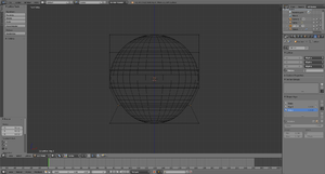
[edit | edit source]- Start with a new Blender scene, delete the default cube and add a UVsphere ( Shift + A > Mesh > UV sphere). Accept the default 32 Segments and Rings. You could use any of the mesh shapes but because the sphere is heavily subdivided (made up of lots of edges and faces), you will get a better idea of what the Lattice is doing.
- Tab back into Object Mode then add a Lattice. It is generally wise to resize the Lattice so that it surrounds the mesh it will be deforming. So, press S and enlarge the lattice to 2 BU wide.
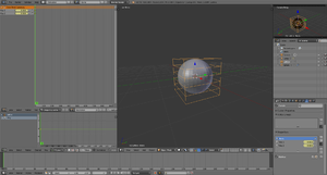
- Select ( RMB ) the Sphere and add a Lattice Modifier to it. Make sure that you type the exact Lattice name correctly into the box. Nothing appears to happen but that's fine. In newer Blender versions click the field under the label "Object:" and select the desired lattice object from the drop-down menu.
- Now select your Lattice, Tab into Edit Mode, select just one control point (a control point looks like a vertex) on the Lattice and move it around. You will see the sphere mesh stretching and squashing relative to that control point. Move each Lattice control point one at a time and see just how far you can deform the mesh. Zoom in your 3D window if you need a closer look.
- The control points of the Lattice can be moved, scaled and rotated in the usual ways. Try selecting a few of all the control points and scaling them ( S ) or Rotating them ( R ) and watch the mesh follow along.
- Now, exit Edit Mode ( Tab ) and select the sphere in Object Mode. Go to the modifiers panel and press the big "X" button to remove the modifier. Despite all that deforming, the sphere immediately returns to its original size and shape. Nothing was really changed in the sphere's mesh data. Immediately re-apply the modifier as before and see the Lattice immediately apply its own deformation to the sphere again.
Getting more involved with Lattice
[edit | edit source]
The default Lattice is two control points high, two wide and two deep, i.e., it is two control points wide in each direction (these are referred to as the U, V and W directions). However, we can change the number of control points in one, two or all directions. This is done by selecting the Lattice, going to the Lattice Panel ( F9 ) and changing the values in the U, V & W buttons. If you decrease one figure to a value of 1, the Lattice will become two-dimensional (planar). Decreasing two values to 1 will change the Lattice to a line (one dimension). This can be useful, especially if the remaining value is increased, but is not the most common usage of Lattice.

UVW settings for Lattice
NOTE: The "Make Regular" button will set the UVW control points of an unscaled Lattice to be exactly one Blender Unit apart in each direction. The "Outside" button effectively removes all the internal control points which are added when the UVW settings are higher than 2.
In most situations you will want to increase some or all the values as this gives you more control over complex deformations, much like a subdivided mesh. How much you increase the UVW directions depends entirely on how much detailed control you need over deformations. As you've already seen basic squash, stretch, shear and simple deforms can easily be achieved with the default 2,2,2 Lattice but by increasing the UVW values a little, a whole new range of deform possibilities becomes available.

Three Lattices with different UVW settings
One thing to understand, however, is that a Lattice cannot bend the individual edges of a mesh (the lines connecting any two vertices) so the mesh must contain enough edges in order to apply complex lattice deformations to it. These edges must be genuine edges and not the virtual edges created by a subsurf modifier (Correction: Yes, they can be edges generated by a subsurf modifier, provided the subsurf comes above the lattice in the modifier stack for the object being deformed; use the up/down-arrow buttons next to each modifier to rearrange them as necessary). Edges can also be added to a mesh using a variety of tools including subdivide, knife and loop cuts (some info on these [[1]]).
New Note: Use K to open a menu for the knife, loop cuts, etc. Knives are used to add a vertex to each line you left click and drag the cursor over, and loop cuts allow you to make multiple cuts into your active object.
About loop cuts: Ctrl + R also is a direct shortcut to a loop cut. Furthermore, loop cuts' main uses are for subsurf modeling. In order to accomplish a hard edge in a subsurfed object (for example the edges and corners of a wooden table or the bumpers of a car) you must apply loop cuts to the faces surrounding the edge and place them very close to them (and parallel). Experiment with a simple subsurfed cube and you'll see. Keep in mind this is why when modeling it is highly recommended to use quads. A loop cut will only cut a quad face, or every face connected with it in one direction, but only quads. Another main reason why it is recommended to model with quad faces is regarding animation but I suppose other tutorials will deal with that later. More information: [2]

A simple subdivided cube after a complex lattice deformation
Intermediate Exercise
[edit | edit source]For this exercise, start over with a new scene and repeat Steps 1 - 3 in the Basic Exercise above. Don't go into Edit Mode yet.
Basic Exercise:
1. Start with a new Blender scene, delete the default cube and add a UVsphere (Spacebar>Add>Mesh>UVsphere). Accept the default 32 Segments and Rings. You could use any of the mesh shapes but because the sphere is heavily subdivided (made up of lots of edges and faces); you will get a better idea of what the Lattice is doing.
2. Tab back into Object Mode then add a Lattice. It is generally wise to resize the Lattice so that it surrounds the mesh it will be deforming. So, press S and enlarge the lattice to 2 BU wide.
3. Select ( RMB ) the Sphere and add a Lattice Modifier to it. Make sure that you type the exact Lattice name correctly into the box. Nothing appears to happen but that's fine.
- In Object Mode, select the Lattice then press F9 and go to the Lattice Panel. Increase all the UVW values to 4. You will immediately see the change displayed in the 3D window.
- Tab into Edit Mode and play with the control points again. The first thing you might notice is that the corner control points have less influence now than before. This is because the effect is proportional to the distance of each point from the mesh. Move some points in the middle of a side face and you'll see the effect is significantly greater.
- Try selecting groups of control points and pulling them away from the Lattice to stretch lumps and bumps out from the mesh. If you are familiar with the proportional edit tool, try that too - it works on Lattices just like it does on meshes.
Try doing the same exercise but increasing values in only the W direction. (U divides in the X direction, V divides the Y direction and W divides the Z direction). So, set the UVW to 2,2,4 and play with the control points again in Edit Mode. Select the two rows of control points around the centre of the Lattice and scale them up ( S ) then Scale them down along Z-axis only ( S Z ). Try other transforms constrained on different axes for interesting, controlled results.
There are three different options for how the Lattice Modifier affects each UVW direction. These are Linear, Cardinal and B-Spline. All I can say is that B-Spline is the default and to find out what the difference is, press the buttons and see.
Examples
[edit | edit source]
Some examples of a Lattice deforming a standard UV Sphere mesh (not smoothed)
Making it stick
[edit | edit source]To keep the mesh deformed permanently, you can select it and press the "APPLY" button in the Lattice Modifier panel. This "bakes" the mesh in the deformed position and disconnects it from the Lattice. The Lattice can then be deleted without the mesh returning to its original shape. This is useful if you are using the Lattice as a modelling tool rather than an animating tool.
Also, instead of deleting the Lattice, you can use it to immediately modify another mesh. Simply move the Lattice over the new mesh in Object Mode then apply the Lattice Modifier to the new mesh. If the Lattice is already in a deformed state, the mesh will immediately be deformed too. Press Apply again to "bake" that mesh and keep re-using the already deformed Lattice on as many other meshes as you wish for matching results.
[Noob Note: I found it interesting that you can even apply the lattice deformation to the original object again once baked, and it will deform even further.]
Animating a Lattice
[edit | edit source]Lattice animation uses a workflow almost identical to the RVK (Relative Vertex Key) workflow from Blender 2.37 and earlier. You don't need to know this but some people might find the information useful.
With your Lattice Modifer already added to your object, select the Lattice and press I to tell Blender you wish to animate the Lattice. Choose "Lattice" from the pop-up list. This sets the basis key (undeformed state) for the Lattice.
Adding the basis key
In the Editing panel (F9), press the "Relative" button.

Set the keys to "Relative"
NOTE: The Slurph setting determines the delay, in frames, for how long it will take to morph from their former state to the one applied by the new lattice.
To set your first deform key, press I-Key and then "Lattice" again then enter Edit Mode. Deform the Lattice by scaling or moving control points then Tab back into Object Mode. If you open an Action Window now, you will see your first key, "Key 1", added to the list. If you press the small arrow at the top of the list, it will display the slider for that key.

Lattice key sliders in the Action Window
[Noob note for blender 2.48a] In the action window, select "ShapeKey editor" in the dropdown "editing modes for this editor" (in the panel header)
To add more Lattice keys, for a variety of deform shapes, repeat the process: I-Key, Tab to Edit Mode, move control points, Tab back to Object Mode. Each time you exit edit mode, a new key will be added to the list in the Action Window.
Animating the Lattice uses the same process as animating Shape Keys for meshes.
If you want the object to begin undeformed, then set each key slider to zero on the first frame of the animation. Move through the frames, setting the sliders as you go to deform the Lattice as desired. You will often find you'll need to set a key before and after each deform key in order to control the rate at which deformations take place in the animation.

Setting keys in an animation
Noob note: I'm doing everything as described and get no keys in action window when exiting Edit mode... Any suggestions?
Noob note; Is it possible to create a keyframe using the object's mesh rather than applying a lattice?
Noobie note: What to press after I-Key? I'm not getting any keys in the action window, help please.
Another Noob: No keys here. I got something changing to IPO Curve Editor and choosing Shape in IPO Type
Noob note; Select Action Editor header->Shape Key Editor. Make sure you also selected Buttons Window->Editing (F9)->Relative Keys
Noob Tip: I am seeing a possible bug in 2.49 in which the key sliders will not appear on the Action Editor unless there is at least one window set to Action Editor when the keys are created. To reveal key sliders for keys that have already been created, save the file, re-open it, set one window to "Action Editor" set the window sub-type to "Shape Key Editor" then switch the Lattice "Relative" setting on and off (putting the cursor over the Action Editor window and hitting HOMEKEY will help locate the sliders). Or, by preference, make sure at least one window is set to "Action Editor" before creating the keys.
Noob note: I couldn't see the sliders either; then I scrolled up and there they were, off the visible portion of the window. However, I had by then change the window type a few times, so I can't rule out that that did something first.
|
|
Applicable Blender version: 2.78. |
Creating Shape Keys
[edit | edit source]
We are going to animate the lattice using Shape Keys. Open a new Blender file, get rid of the default cube, and add a new UV Sphere with 32 segments and 32 rings. Then add a new Lattice and upscale it 2 times so it becomes visible ( S 2KEY Enter ). Scaling the lattice does not have any effect on shape of the sphere until the lattice is deformed. When adding new objects the 3D Cursor should be in the same spot (centering your cursor using Shift + C is recommended). Consequently the sphere and the lattice will have the same center. Finally, select the sphere, add a Lattice modifier, and select previously created lattice as object.

For the sake of simplicity we will only deform the sphere by making it wider or narrower. To achieve this, we will need to give our lattice more vertices that can be tweaked by adjusting the UVW parameters. In the Lattice context ![]() set the W to 6. Also check the "Outside" checkbox to have vertices only on the edges of the lattice cube (again, for the sake of simplicity). Lattice parameters have to be set before adding any shape keys. You will not be able to change them later.
set the W to 6. Also check the "Outside" checkbox to have vertices only on the edges of the lattice cube (again, for the sake of simplicity). Lattice parameters have to be set before adding any shape keys. You will not be able to change them later.
Before deforming the lattice, add the "Basis" shape key:
- Select the lattice.
- Go to the Lattice Object Data context
 in the Properties window.
 - Under Shape Keys press the "+" button and the "Basis" key will appear (note that the UVW parameters are grayed out now).
The "Basis" key represents our starting point (shape). When no others shape keys affect the shape of the lattice (their values are 0), its shape is only governed by the "Basis" key.
Now let's deform the sphere with additional shape keys to be able to animate the deformation later. The basic procedure is as follows:
- Have the lattice selected in Object Mode.
- Add a new shape key by clicking the "+" button once more. "Key 1" or similar should appear in the list. Naturally, you can rename the shape key by double-clicking on its name and entering a new one.
- Go to Edit Mode and deform the lattice to your liking. You are editing the shape key that is currently selected.
- Go back to Object Mode.
You have probably noticed that your shape keys appear to have no effect when back in Object Mode. This is because their values are set to 0 by default. To change how your sphere really looks, select a shape key you have previously defined in the Lattice context ![]() , and set the "Value" slider to, for example, 1. If you have multiple shape keys defined, you may also "mix" them by setting multiple shape key values to non-zero. There are two more things to note:
, and set the "Value" slider to, for example, 1. If you have multiple shape keys defined, you may also "mix" them by setting multiple shape key values to non-zero. There are two more things to note:
- The "Basis" key does not have a value. It is a starting point after all.
- In Edit Mode you edit shape keys one by one (separately). You could imagine that the value of the currently selected shape keys gets set to 1 and all other values are set to 0 while in Edit Mode.
In this example we will create only two shape keys (beside the "Basis") and perform two simple deformations on the lattice (which will consequently deform the sphere, since the Lattice modifier is active), which will result in a goblet-like shape. Create a new shape key "Key 1" before deforming the lattice further. This way you will edit the new key instead of the "Basis". Go to Edit Mode and switch to front orthographic view (keys NUM1 and NUM5 ). Use Border Select ( B ) to select the top row of lattice vertices and upscale them in the XY plane (or non-Z directions, use S Shift + Z ). Go back to Object Mode, create shape key "Key 2" and, as shown before, downscale the second row of lattice vertices from the bottom. When back in Object Mode, you can set the value of both shape keys to 1 and observe the combined deformation of both keys. This will be our final shape in animation.
Note that there is no "Limit selection to visible" button ![]() in Edit Mode when editing a lattice. When using Border Select or similar tool, the vertices are selected even if they are not visible, so there is no need to switch to wireframe view to be able to select whole rows in the Front view.
in Edit Mode when editing a lattice. When using Border Select or similar tool, the vertices are selected even if they are not visible, so there is no need to switch to wireframe view to be able to select whole rows in the Front view.
-
 Defining the first shape key.
 -
 Defining the second shape key.
 -
 The result with both shape key values set to 1.


Animating Shape Key Values
[edit | edit source]

In previous steps we have created our objects, added a Lattice modifier, and defined the shape keys. This is all we need to proceed to shape key animation. The concept is very similar to animation of any other values. We will be, however, using one additional tool. Folow these steps to set up the interface you will need:
- Open a new Dope Sheet
 window or, even better, switch your screen layout to "Animation". Examples use the latter method.
 - In the Object Mode of 3D View select the lattice object.
- Switch the context of the Dope Sheet window to "Shape Key Editor" using the box in the window's header. Your shape keys should show up in the Dope Sheet Summary.
Shape key values have grey background. This means they are not animated (yet). We will make the sphere deform from its original shape ("Base" key) to the goblet-like shape (influenced by "Key 1" and "Key 2"). Before going forward with examples, we will learn the basic keyframing procedure for shape key values.
- Set the frame number. Either position the green bar cursor in the Dope Sheet to the desired frame using LMB , or use controls in the Timeline window
 . For more information about frames see Basic Animation.
 - Change the shape key values in the Dope Sheet Summary either by pressing LMB and dragging, or clicking on the slider and typing the desired value. Notice that Blender inserts a keyframe for changed values as soon as you do (indicated by yellow diamonds in the Dope Sheet). Keyframed values should change their background colour to yellow (means that the value is keyframed in the currently selected frame) or green (means that the value is keyframed in some other frame).
- Once the keyframes are added, values of keyframed shape keys will be shown in the Graph Editor
 as well, allowing you to fine-tune them to your liking using F-Curves.
Alternative method is to insert keyframes in the Lattice Object Data context ![]() . Select a Shape Key and adjust its value using the slider below. Then RMB the slider and select "Insert Keyframe".
. Select a Shape Key and adjust its value using the slider below. Then RMB the slider and select "Insert Keyframe".
Now let's animate the sphere using this procedure. Make sure you see the Shape Key Editor context of the Dope Sheet and have your lattice selected in Object Mode of the 3D View. Shape keys should be shown in the Dope Sheet Summary. Set your frame to 1. This is the first frame of our animation (indicated by the "Start" field in the Timeline). In the Dope Sheet Summary set both shape keys values to 0 (note the diamonds -- keyframes -- appearing). This means that in frame 1 our sphere will be shaped only by the "Basis" key. Go to frame 10 and set the value of "Key 1" to 1. The following will cause the top of our sphere to deform during frames from 1 to 10. Do not forget to insert a keyframe for "Key 2" (value 0) at frame 10. To do this just set the value to 0 again or RMB → Insert Keyframe. Dope Sheet should show an orange line connecting the two diamonds, showing that values in these keyframes are the same (nothing is happening with this shape key). If you do not add this keyframe, the bottom will start deforming at the beginning of the animation. Meanwhile you may use the mouse wheel or drag the ends (dots) of the sliders in the Dope Sheet and Graph Editor windows to zoom in the view. Go to frame 20 and set the value of "Key 2" to 1. Similarly, this will cause the bottom of the sphere to deform during frames from 10 to 20 while the top is already deformed. Finally, set the "End" field in the Timeline to 30, which will stop our animation at frame 30. Feel free to play your new animation using controls in the Timeline. Also feel free to add additional keyframes and tune the transitions to your liking in the Graph Editor. In addition, you might want to try scaling, moving, and rotating the deformed lattice (the situation at frame 30 for instance) in Object Mode of the 3D View to see what happens to the sphere.
-
 Frame 1
 -
 Frame 10
 -
 Frame 20


Let the fun begin!
[edit | edit source]Now you have your object safely locked away inside your Lattice, you can still animate the object itself, inside the Lattice!
Why would I animate the object too?
[edit | edit source]Take the case of the classic cartoon eyeball which is taller than it is wide. If you just stretched the sphere object itself, instead of using a Lattice to deform it, then you couldn't properly rotate the eyeballs to look up and down because the whole "egg-shaped" eyeball would rotate and end up lying on its front or back. The eyes would literally pop-out of the head.

Cartoon eyes: The stretched spheres don't rotate properly.
If, however, you use a Lattice to deform the basic sphere to make it into a tall "egg" shape, you can still select the eyeball itself and animate it within the Lattice. Now when you rotate the eyeball, it will look up and down but still maintain its deformed shape within the head.

Cartoon eyes: Spheres deformed with Lattice can still be rotated with good results.