Blender 3D: Noob to Pro/Mountains Out Of Molehills
|
|
Applicable Blender version: 2.75. |
Now that we've created our simple person, it's time to give him somewhere to go. In this tutorial we'll create a mountain range using a few simple, and handy tools.
Creating a simple plane
[edit | edit source]
First we need a clean area to work with.
- Start off with a new project, using File → New, or hit Ctrl + N . If you have a default cube or plane just delete them now (select them with RMB and press X ).
Our first step is to create a large grid plane that we'll use for the ground and grow our mountains out of.
- Press NUM7 to enter top view. This way our grid plane will be lying flat when we create it.
- Press Shift + C . This sets the 3D cursor to (0,0,0) which will be the center of the grid we will add (or use - Shift + S → Cursor to Center).
- Now add the grid with Shift + A → Mesh → Grid. This will be our canvas.
- Now add more vertices to the grid. In the bottom of the toolbox window, change the number of X and Y subdivisions somewhere from 15 to 20.
- Change to Edit Mode using Tab
- Scale the grid plane up by about 15
- First put the mouse close to the center of the grid plane and press S and drag the cursor away and watch the numbers in the bottom left of the 3D View. Hold Ctrl while dragging to increment by 0.1 for a more precise measurement. Alternatively, to enter the exact amount yourself, press S , then simply type 15 and hit Enter .
First mountain
[edit | edit source]Now that we have the ground, it's time to start growing our mountains.
- Make sure you have nothing selected A .
- Select a random vertex with RMB . I usually start at the one that is 4 down from the top and 4 in from the left (the 4th vertex if you count the edges).
- Change to the side view with Num3 .

- Press O to change to proportional edit mode or use the button which shows a grey ring on the header of the 3D View. The button will change its color to blue. You can also use Space → Transform→Proportional Edit (By default this button is located just below the 3D view).
- Once you've turned proportional edit mode on, another button appears to its right, the falloff button. Select Smooth Falloff here. Alternatively you can use the menu on the header of the 3D View (Mesh → Proportional Falloff → Smooth) or, using Shift + O will cycle through all of the different falloff types while using the Proportional editing tool.
- Press G to grab the vertex. We should now have a circle surrounding the vertex, this is our radius of influence. Basically any vertices inside this circle will be affected by any changes to the vertex itself.
Noob Note: If you're having trouble seeing or changing the radius of influence, try saving your scene and restarting Blender.
- Use SCROLL or PgUp and PgDown to adjust the radius of influence to include just over 2 vertices on each side of our selected vertex. (Depending on your version of Blender, you may need to use LMB + SCROLL to adjust the radius of the influence. On Mac, use Fn + PgUp and Fn + PgDown ).

- Move the vertex up about 8 units on the Z-Axis. Do this by dragging the cursor up a little, and press the MMB ; this should restrain the movements along the Z-axis. Now use Ctrl to move it precisely. Alternatively you can use Z to restrain movements to the Z-Axis, type 8 and hit Enter . In older versions of Blender you may need to hit N before typing 8 .
Congratulations, we just created our first mountain. Now it's time to see what other things we can accomplish with the proportional editing tool.
Peaks vs. hills
[edit | edit source]
The 2.37 and onward releases offer at least 6 types and 2 modes of proportional editing. The previous release only has 2 of these types: Smooth and Sharp Falloff. We'll take a look at the difference between these two now.
- Change to top view again with Num7 . You'll notice that now your "mountain" looks like a few differently shaded squares in the grid; you're looking down on shaded tiles, but in the Z axis, they're all still perfectly aligned with the original grid.
- Select another vertex away from the first. Let's say 4 from the bottom 4 from the right (counting the vertices on the edges).
- Change back to the side view with Num3
- Select Sharp Falloff from the menu on the bar of the 3D View. Alternatively, using Shift + O will switch from one to the next of the 6 proportional editing modes while using the Proportional editing tool.
- As before, move the vertex up 8 units on the Z-Axis (Note: The radius of influence will still be the same size as when we last used it).
- G
- Z
- Type Num8 and hit Enter

Now we can see the differences between the sharp and smooth falloff. The same number of vertices are affected in both cases; only the degree to which they are affected is different.
The different proportional editing modes can be selected from the box immediately to the left of the proportional editing type box. The mode box contains four options: Disabled, Enabled, Connected, and Projected (2D). "Disabled" means that proportional editing will not be used. "Connected" means that only vertices linked to the selected vertices will be affected by the radius of influence. "Enabled" means that all vertices will be affected.
Shaping the world
[edit | edit source]
Now that we've created a couple of Mountains, it's time to see how we can use proportional editing to shape them.
- First make sure we're in side view ( Num3 ).
- Then on the smooth falloff mountain, the first one we created, select the vertex that is immediately down and left from the topmost point.
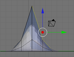
- Press R to rotate, scroll the MMB to change effective radius so it includes other points. Your screen should look like the photo to the right.
You can see the size of the proportional editing circle, and that there is only one vertex on the mountainside selected.
- Next hold Ctrl and rotate everything by -90. Alternatively, use R , N , and type -90 and press Enter . Your mountain should now look like this:
Noob note: be careful about the range of affected vertices. If the range is too small, then rotating will affect just the selected vertex. If the range is too large, it will rotate everything together. You can adjust the range by using SCROLL .

Notice that the vertex itself did not move; since it is at the center of the circle it had no effect. The adjoining vertices within the edit circle were rotated around it in decreasing amounts the further from the center they are. Try doing it again with a larger proportional editing circle. Feel free to play around with scaling or rotating from different view points (don't forget that you can also use G to move vertices vertically or horizontally).
Try viewing your world from top view while rotating with a large effective radius. You will see the nearby vertices move close to the full amount while vertices further away move less.
Smoothing things out
[edit | edit source]
Now that we have a couple of budding mountains, you probably think they look kind of choppy. Sure they would be good if we were making an 8-bit console game, but we're working with 3D here, we want things to look sharper (or maybe smoother) than that. There are a couple of approaches to this. The first is to use more vertices when we create our plane. And I won't lie, it works. But it's also a HUGE resource hog. It would take your home computer hours of work just to keep things updated, let alone run it. So instead, we fake it. The easiest way to do this is to turn on SubSurfaces (we saw this in Detailing Your Simple Person 1.) For our purposes, let's set the subdivision (Levels) to 2. Also, ensure our SubSurf algorithm is set to Catmull-Clark (this is the default setting).
Now, you'll notice that with SubSurf on, we lose a lot of hard edges that we had, essentially we have no sharp corners any more. I don't know about you, but to me that doesn't make for a very interesting mountain range. So to restore our corners, we are going to use Weighted Creases for Subsurfs.
- First turn off proportional editing with O , and ensure we're in side view with Num3
- Next, while still in edit mode, change to Edge Select mode with Ctrl + Tab and select Edges. Alternatively press Edge Select Mode button at the bottom of the object window.
- In the Tool Shelf at left, select the Options tab, then under Edge Select Mode, choose Tag Crease.
- On our Sharp Falloff mountain, the second one we did, select the two edges on the right. (see image below)
- Press Shift + E or Space → Edit → Edges → Crease SubSurf, then move the mouse away from the edge until the edge Crease reads 1.000 in the 3D viewport header. If moving the cursor there seems to be impossible, just hit 1 and enter.

As you move the cursor away from the edge you will notice two things. The first is that the edge becomes thicker as we move from it; this is showing how much of a crease we have (with Draw Creases turned on). The second is that you will notice the subsurfed mesh moving closer to the edge as the sharpness increases.
Naturalness
[edit | edit source]Press Ctrl + Tab to enter Edit Mode and select vertices. Then go into front view Num1 . Select the second vertex from the top in the centre of our Sharp Falloff mountain, then go into side view Num3 . Hold G and drag the vertex inwards, not too far or your mountain will come out of itself on the other side. Just bring it in enough to make a small indent.
Then grab the top vertex and pull it down a small amount. You will notice that there is a small "crunch" in your mountain.
Don't forget to select all with A , then W Shade Smooth button to smooth everything out.
OK, so your mountains are starting to shape up. But they still look a bit too neat. You could spend time moving each individual vertex but the chances are your model will still lack the natural feel. What we need is some chaos. Thankfully this is quite easy to accomplish. Firstly select the vertices that make up your mountains, all of them and a few around the base (box and circle select will make this easier). Select a few vertices between the mountains too. Next we use something called fractals. Fractals are chaotically (i.e. randomly) generated variables. In short you can use these variables to give your mountains a "wobbly" look.

In the Tools tab of the Tool Shelf, press Subdivide (under Mesh Tools), then look at the Subdivide submenu below. The value in the Fractal box is the strength of the fractal. 1 is very low and will barely change your model. 10 is very high and will twist your models into very odd shapes indeed. Have a play with different values until you find one that you like. Around about 4.0 should do it. Hit OK and presto, your mountains have been transformed from clinical neatness, to lumpy chaos.
- If you make too many fractals, your computer will slow down. However, the more you add, the more bumpy and realistic it looks!
Repeatedly using the fractal tool seems to rapidly multiply the amount of vertices on your canvas. I suggest using the tool once, and if the result isn't satisfying, undo the result ( Ctrl + Z ) and try it again with a different fractal strength. Helpfully, even after undo, your selected vertices remain selected.
Now go back into Object mode and view the result.