Game Creation with XNA/Print version
| This is the print version of Game_Creation_with_XNA You won't see this message or any elements not part of the book's content when you print or preview this page. |
Table of contents
Basics
Game Creation / Game Design
- Introduction
- Types of Games
- Story Writing and Character Development
- Project Management
- Marketing, Making money, Licensing
Mathematics and Physics
- Introduction
- Vectors and Matrices
- Collision Detection
- Ballistics
- Inverse Kinematics
- Character Animation
- Physics Engines
Programming
Audio and Sound
2D Game Development
- Introduction
- Texture
- Sprites
- Finding free Textures and Graphics
- Menu and Help
- Heads-Up-Display (HUD)
3D Game Development
- Introduction
- Primitive Objects
- 3D Modelling Software
- Finding free Models
- Importing Models
- Camera and Lighting
- Shaders and Effects
- Skybox
- Landscape Modelling
- 3D Engines
Networking and Multiplayer
Artificial Intelligence
Kinect
Other
Appendices
References
License
Preface
To start writing games for Microsoft's XBox360, one usually has to read many books, web pages and tutorials. This class project tries to introduce the major subjects, get you started and if needed point you into the right direction for finding additional material.
The idea behind this class project came from a colleague who suggested that most class projects produce really nice results, but usually disappear in some instructors' drawers. After reading on the possibility of using Wikibooks for class projects, we just had to give it a try.
Getting Started
If you are new to Wikibooks, you might first want to look at Using Wikibooks. Details for creating a class project can be found at Class_Project_Guidelines.
Other Wikibooks
There are also other wikibooks on subjects related that are quite useful:
- Creating a Simple 3D Game with XNA
- Video Game Design
- Blender 3D: Noob to Pro
- C Sharp Programming
- Introduction to Software Engineering
- Game Creation with the Unity Game Engine
Other Class Projects
Inspiration from successful class projects can be drawn here, which by themselves are also quite interesting and maybe helpful for this project:
Basics
Introduction
Game development is neither easy nor cheap, instead it is a multi-billion dollar, fast growing industry. It is challenging in terms of hardware and software, always using cutting edge technology.
The XBox 360 contains gaming hardware which is among the most sophisticated available. It has a PowerPC-based CPU with 3 cores running at 3.2 GHz with 2 threads each. For graphics it uses a custom ATI Graphics (Xenos) card running at 500 MHz with 48-way parallel floating-point shader pipelines.
Hence, in game development we have already made the paradigm shift away from the single-core single-threaded application, because in the XBox we are dealing with 6 threads running in parallel on the CPU, with 48 threads running in parallel on the GPU and with hundreds of GFLOPS computing power. Therefore, game programming is parallel programming!
So how can we learn about game development, how can we get started? Microsoft with the XNA Game Studio and the XNA Framework has made it pretty easy to get started. With openly available components, even a 4th semester student can start writing a 3D race car simulation. A very nice feature of the XNA Game Studio is the fact that you can run the programs not only on the Xbox, but also on the PC, which is very nice for development.
Before we can get started writing code, we need to get our environment set up, install necessary software, including Visual Studio, learn a little about C# and the basics of game programming. Also handling of input devices is covered here.
Setup
For this book we will use Visual Studio 2008 and the XNA Framework 3.1. Although there are newer versions available, for many reasons we will stay with this older version.
Preparation
You should first make sure that you have a newer version of Windows, such as XP, Vista or 7, with the appropriate service packs installed. In general, it is a good idea to use the US version of the operating systems. In addition, since at least DirectX 9 compatibility is needed, you may not be able to use a virtual machine (such as Parallels, VMWare or Virtual Box) for doing XNA programming.
Install Visual C# 2008 Express Edition
First download the C# 2008 Express Edition from Microsoft. You can also use the Visual Studio Express version. Installation is straightforward, simply follow the wizard. After installation, make sure you run Visual Studio at least once before proceeding to the next step.
Install the DirectX Runtime
Download and install the 9.0c Redistributable for Software Developers. This step should not be necessary on newer Windows version. First, try to get away without it, if in a later part you get some funny error message related to DirectX, then execute this step.
Install XNA Game Studio 3.1
After having run Visual Studio at least once, you can proceed with the installation of the XNA Game Studio. First, download XNA Game Studio 3.1. Execute the installer and follow the instructions. When asked, allow communications with XBox and with network games.

Test your Installation
To see if our installation was successful, let's create a first project.
- Start Visual C# 2008 Express Edition
- select File->New Project under 'Visual C#->XNA Game Studio 3.1' you should see a 'Platformer Starter Kit (3.1)', click OK to create the project
- to compile the code use either 'Ctrl-B', 'F6' or use 'Build Solution' from the Build menu
- to run the game use 'Ctrl-F5', enjoy
- take a look at the code, among other things, notice that a 'Solution' can have several 'Projects'
Next Steps (optional)
We will only develop games for the PC, if you want to develop games for the XBox also, you need to become a member of XBox LIVE and purchase a subscription (in case your university has a MSDN-AA subscription, membership is included).
Advice
You need to be attentive of which XNA version you have to install.
Compatible versions:
| Visual Studio | XNA Game Studio |
|---|---|
| 2005 | 2.0 |
| 2008 | 3.0, 3.1 |
| 2010 | 4.0 |
Authors
Sarah and Rplano
C-Sharp
When coding for the XBox with the XNA framework, we will be using C-Sharp (C#) as programming language. C-Sharp and Java are quite similar, so if you know one, basically you know the other. A good introduction to C-Sharp is the Wikibook C_Sharp_Programming.
C# has some features that are not available in Java, however, if you know C++ some may look familiar to you:
- properties
- enumerations
- boxing and unboxing
- operator overloading
- user-defined conversion (casting)
- structs
- read-only fields
The biggest difference between C-Sharp and Java probably are the delegates. They are used for events, callbacks and for threading. Simply put, delegates are function pointers.
Properties
This is an easy way to provide getter and setter methods for variables. It has no equivalent in Java, except if you consider the automatic feature of Eclipse to add these methods. Simply consider the following example, notice the use of the value keyword.
Enumerations
In Java you can use interfaces to store constants. In C# the enumeration type is used for this. Notice that it may only contain integral data types.
Boxing and Unboxing
This corresponds to Java’s wrapper types and also is available now in Java. Interesting to notice is that the original and boxed are not the same. Also notice that unboxed stuff lives on the stack, whereas the boxed stuff lives in the heap.
Operator Overloading
This is a feature that you may know from C++, or you might consider the overloading of the ’+’ operator for the Java String class. In C# you can overload the following operators:
- unary: +, -, !, +, ~, ++, --, true, false
- binary: +, -, *, /, %, &, |, ^, <<, >>, ==, !=, <, >, <=, >=
For instance for vector and matrix data types it makes sense to overload the '+', '-' and the '*' operators.
User-Defined Conversion
Java has built-in casting, so does C#. In addition, C# allows for implicit and explicit casting, which means you define the casting behavior. Usually this makes sense between cousins in a class hierarchy. However, there is a restriction: conversions already defined by the class hierarchy cannot be overridden.
Structs
Structs basically allow you to define objects that behave like primitive data types. Different from objects, which are stored on the heap, structs are actually stored on the stack. Structs are very similar to classes, they can have fields, methods, constructors, properties, events, operators, conversions and indexers. They can also implement interfaces. However, there are some differences:
- structs may not inherit from classes or other structs
- they have no destructor methods
- structs are passed by-value not by-reference
Read-Only Fields
When we were discussing the keyword const the difference to Java’s final was that you had to give a value to it at variable declaration time. A way around this is the readonly keyword. However it still has the restriction, that a readonly variable has to be initialized inside the constructor.
Delegates
Usually, in Java when you pass something to a method, it is a variable or an object. Now in C# it is also possible to pass methods. This is what delegates are all about. Note that delegates are also classes. One good way of understanding delegates is by thinking of a delegate as something that gives a name to a method signature.
In addition to normal delegates there are also multicast delegates. If a delegate has return type void, it can also become a multicast delegate. So if a delegate is the call to one method, then a multicast delegate is the call to several methods, one after the other.
Callbacks
Callback methods are used quite often when programming C or C++ and they are extremely useful. The idea is instead of waiting on another thread to finish, we just give that thread a callback method, that it can call once its done. This is very important when there are tasks that would take a long time, but we want the user in the meanwhile to do other things. To accomplish this, C# uses delegates.
Inheritance
Object-oriented concepts in C# are very similar to Java’s. There is a few minor syntax related differences. Only with regard to method overwriting in an inheritance chain, C# provide more flexibility than Java. It allows for a very fine-grained control over which polymorphic method actually will be called. For this it uses the keywords 'virtual', 'new', and 'override'. In the base class you need to declare the method that you want to override as virtual. Now in the derived class you have the choice between declaring the function 'virtual', 'new', or 'override'.
Game Loop
Programming a game consoles (GC) is not quite the same as programming a regular PC. Whereas PC's have sophisticated operating systems such as Windows, Linux or Mac OS, on a game console we are much closer to the hardware. This has to do withe the special requirements of games. We must consider the following differences between PC’s and GC's:
- on a GC usually only one (multithreaded) program is running, thus there is no real OS
- on a GC raw graphics power is needed, but there is no GUI with windows and widgets
- a GC usually has no keyboard, console, sometimes not even a harddisk
Hence, you will find no classes with names like Window, Form, Button or TextBox. Instead you find classes with names such as Sprite, Texture2D and Vector3. We talk about Content Pipeline, Textures and Shaders.
Usually, programs for PC's are event driven, meaning the user clicks somewhere something happens. If the user doesn't click anywhere, nothing happens. On game consoles (GC) this is a little different. Here we often find the so-called Game Loop. For the Xbox 360, or rather the XNA framework, it consists of three methods:
- LoadContent()
- Update( GameTime time )
- Draw( GameTime time )
LoadContent() is called once at the start of the game to load images, sounds, textures, etc. Update() is used for getting user input, updating the game state, handling AI and sound effects. Draw() is called for displaying the game. (MVC Pattern). The Game Loop then consists of the two methods Update() and Draw() being called by the engine. They are not neccessarily called in sequence!
Input Devices
Introduction
Input Devices is one of the most important chapters in a handbook for game creation. A computer (or Xbox) game subsists on interaction with the user - that is why there needs be to a method to check the user input and to let game react on this input.
XNA makes it very easy to control the user devices. It offers an easy-to-use and understandable API for access to mouse, keyboard and gamepad. Using this it is possible to write an user-interaction scheme in a short time. Basically XNA offers easy access to:
- Mouse
- Keyboard
- Gamepad
The basic concept is the same for all controller types. XNA provides a set of static classes (one for each type) which can be used to retrieve the status and all properties (e.g. pressed buttons, movements, ...) of the input device.
This detection is usually located in the Update()-method of the game loop to retrieve the status as often as possible. Storing the states of all input devices in class variables allow it to check the status in other methods and classes. It is a common solution to have an array of boolean variables in the class which represent the status of all controllers - namely the pressed buttons on the controller, the mouse movements and clicks and the pressed keys on the keyboard.
protected override void Update(GameTime gameTime)
{
    KeyboardState kbState = Keyboard.GetState();
    // ...
}
Windows vs. Xbox
Windows and Xbox games are usually played in a different way. In general a Windows computer is controlled by a mouse and a keyboard, whereas an Xbox is often controlled by a gamepad. Therefore it needs a control structure to decide whether the code is executed on Windows or Xbox to set a default controller for the game.
#if XBOX
// this code is embedded only in xbox project
#endif
But it is also possible to connect a mouse or keyboard to an Xbox as well as to connect an Xbox controller to a Windows computer. So in most of the cases it is better to check for example if a gamepad is connected. Another way of dealing with that problem is to store the user's controller of choice in a variable. So the user may decide which controller he likes to use to play your game.
Mouse

At first you have to get an instance of the mouse state by calling the static GetState()-method of the Mouse class. This object now gives you access to a lot of public attributes from the connected mouse.
MouseState mouse = Mouse.GetState();
bool leftButton = (mouse.LeftButton == ButtonState.Pressed); // left mouse button
bool middleButton = (mouse.MiddleButton == ButtonState.Pressed); // middle mouse button
bool rightButton = (mouse.RightButton == ButtonState.Pressed); // right mouse button
int x = mouse.X; // horizontal mouse position
int y = mouse.Y; // vertical mouse position
int scroll = mouse.ScrollWheelValue; // scroll wheel value
The state of the mouse buttons is read through the attribute "xxxButton" (where xxx stands for the type - left, middle, right). If you compare this value with ButtonState.Pressed or ButtonState.Released you can retrieve the state of this button. In the example above it stores the state of each button in a boolean variable that is true if the associated button is pressed.
The mouse position on the screen is stored in the X and Y attribute of the mouse object. This value is always positive (as it starts with 0,0 in left upper corner) and may be compared to further mouse positions (in a game logic) to detect a specific movement of the mouse. A simple example would be:
MouseState mouse = Mouse.GetState();
int x = mouse.X;
int y = mouse.Y;
deltaX = oldX - x; // difference of horizontal positions
deltaY = oldY - y; // difference of vertical positions
oldX = x;
oldY = y;
Most of the modern mouse also have a scroll wheel that is often used in games, for example to zoom, to scroll or to switch between different weapons. The attribute ScrollWheelValue is an integer that represents the scroll state of the mouse.
To recognize the movement of the scroll wheel it is necessary to store some older values and compare them with each other. The sign of this difference indicates the scroll direction and the absolute value indicates the speed of scroll movement.
Keyboard

To check the state of the keys on a keyboard is very simple. At first you have to get an KeyboardState object by calling the static method GetState from the Keyboard class. This instance now lets you retrieve the state of specific keys.
KeyboardState keyboard = Keyboard.GetState();
bool keyB = keyboard.IsKeyDown(Keys.B); // key "B" on keyboard
bool keyArrowLeft = keyboard.IsKeyDown(Keys.Left); // arrow left on keyboard
The boolean variables keyB and keyArrowLeft now store "true" if the specific key is pressed right now or "false" if it is not pressed. This method can be repeated for each key that is of interest for the application or game.
It is also possible to directly get an array of all keys of the keyboard that are currently pressed. A call of the method GetPressedKeys returns an array of Keys that can be traversed key by key.
KeyboardState keyboard = Keyboard.GetState();
Keys[] keys = keyboard.GetPressedKeys(); // array of keys
Gamepad
The gamepad is the most convenient way to play a game on the Xbox. Despite XNA is designed to develop games for Windows as well as for Xbox, the default API only supports the original Xbox controller. Based on that fact you have to decide whether you want to force your user to use (and maybe buy) the Xbox gamepad or if you want to support any other gamepads for example from Logitech.
That might be more comfortable for the user, though it means more coding effort for the developer. In this chapter I want to describe the implementation for both the Xbox controller and all other controllers.
Xbox Gamepad

Accessing this input device is nearly as easy as checking the state of mouse or keyboard. One (and important) difference is that XNA makes it able to connect up to four different gamepads to the Xbox or Windows computer.
So it is (often) necessary to implement a loop over all gamepads that are connected to check their states individually. How this (and more) can be done is explained in the following paragraphs.
GamePadState[] gamePad = new GamePadState[4];
for(int i = 0; i < 4; i++) { // loop over up to 4 gamepads
    gamePad[i] = GamePad.GetState(i); // get state of gamepad
    if(gamePad[i].IsConnected) {
        // gamepad is connected
    }
}
In this loop you can access all attributes like the buttons (front and shoulder), the digital pad and the two analog sticks. Here is how you do it:
bool aButton = (gamePad[0].Buttons.A == ButtonState.Pressed); // button A
bool leftDigital = (gamePad[0].DPad.Right == ButtonState.Pressed); // left button on digital pad
int leftStick = gamePad[0].ThumbSticks.Left.X; // horizontal position of left stick
The rumble effect lets the gamepad vibrate and gives the player a special feedback to his actions in the game. For instance a hit by an opponent in a shooter game or a crash in a racing game could cause such feedback. The second and third parameter control the intensity of the rumbling effect.
GamePad.SetVibration(int controllerNr, float leftRumble, float rightRumble); // make the controller rumble
Other Gamepads

Other gamepads than the original Xbox controller are not supported by XNA. But it is possible to integrate a support for them with a free library which is called SlimDX.
In addition you need a helper class that can be found here - it uses SlimDX to check the gamepad state of controllers that are not the original Xbox controller.
If you have downloaded, installed and integrated both the SlimDX library and the helper class you can use the following code to check the gamepad states - like you have done with the Xbox controller in XNA.
controller = new GameController(this, 0); // number of gamepad
GameControllerState state = controller.GetState();
bool button1 = state.GetButtons()[1]; // button 1 pressed
Kinect

Kinect is a revolutionary video camera for the Xbox that recognizes your movement in front of the television. This can be used to control games just with your body. Developers can use the Kinect framework to integrate this into their game.
Game Creation / Game Design
Introduction
Here we first consider what types of games there are, basics behind story writing and character development. Also project management, marketing, making money, and licensing are issues briefly touched upon.
More Details
Lore ipsum ...
Types of Games
BlaBla about what kind of games are out there, maybe some history. Also include non-computer games, maybe there are some genres.
- role playing
- card games
- chess, go
- browser games / 2nd Life...
- Nintendo
- Playstation/XBox etc
- 2D
- 3D
- strategy
... Write a little chapter about each, giving examples and references, maybe with links where to play them online.
Authors
Story Writing and Character Development
A good game lives and dies with it`s characters and it`s story. A good story is what catches the player, keeps him interested and makes him want to continue. The story is the frame for all the action which is taking place, wrapping everything together. But story alone will never keep the player going. There is no good story without good characters and vice versa. The characters in the story are just as important. Not only the main character, but all characters he is interacting with, all characters who motivate him or influence him to do the things he does. Therefore its most crucial, for a good story, to create the story and all characters within in a way so they form a coherent unity. Imagine a Spacetrooper crossing Frodos way in The Lord of the Rings. That simply would`nt fit and would definitely ruin the story. But what exactly is a good story? And what exactly are good characters, fitting this very story? As always, whether or not a story and its genre are interesting, is a question of taste and lies in the eye of the beholder. Whereas whether a story is written in a good or a bad way, follows certain mechanics. Same applies for the characters in the story. Its personal taste whether you like the good guy or prefer the bad guy. But creating a character which is “self-contained” and well made, again follows certain mechanics.
However you write a story or create your character, is totally up to you. But looking at what other authors and game developers do, makes it easier. There are certain tools and ways how to write the story and create the character for your game. The more detail you want to put in the more research you should do. There are many books out there that might help you to dive deeper int o the matter of Story Writing and Character Development. Covering it all would simply be to much. This article will give you a basic insight into Character Development and Story Writing for Games.
Character Development
On the following pages I will describe techniques to develop/create a character for a game or a story. Character development in terms of progress while playing, gaining experience, increasing level, learning skills and so on, is not part of this article, will be referred to by certain links though. Focus of this article is character creation prior to the game.
Preliminary Work
The probably most important thing when creating a character is to know its purpose. Are you creating the main character of the story, the villain, a sidekick, a servant, a random companion or something else? Knowing the role of the character makes it easier to define his behaviour, his actions, his way of thinking and his overall appearance. After you have chosen the scope of your character, the actual work begins. Inform yourself! Read as much about the type of the character as you can. Ask yourself questions to define the character.
- Do characters like this already exist in other games or stories?
- What has been written by other authors?
- Are there already stereotypes of this character and do they fit to your creation?
- Is he a servant? How does it feel to serve?
- Is he a soldier? How does it feel to be in battle?
- Is he a priest? How does it feel to pray to god?
Learn as much about the character as you can. Check all available resources. Talk to friends. Keep asking questions. If you don't find exactly what your looking for, stick to your own imagination and feelings. In the end it`s your creation. There are certain things to consider though. Do you create a character who is part of an already existing universe (like an orc or a dwarf or a human)? If so think about the characteristics already applied to them. Like, orcs are green, dwarfs a small and humans can’t breath underwater. Do you want to stick to these basic characteristics that are already present in the players imagination, or do you want to create something totally new? However you decide, keep in mind how the player could react on your creation.
Point of View and Background
In order to make your character authentic, try to look through his eyes. Try to be your character and keep your eyes open to the world and how the character perceives it. How do things look? Why do they look like this? How do things feel? Why do they feel that way? What feels good? Why does it feel good? The WHY of things sometimes is more important than the things themselves. To understand the WHY, it is necessary to understand the background of your character.
A real person develops a certain understanding of the world and has an individual point of view on things, depending on his own experience, on his way of growing up and on all the things that happened in his life. And probably only he can tell how he became the person he is today. Since your character is a creation of your fantasy, you are the only one that can tell how he became the character he is. The more specific you describe the characters background the easier it will be for the player to understand him and feel with him. The player must not necessarily agree with the characters attitude, but he will more likely understand it, if you provide a detailed explanation for his behaviour.
The more you think in detail the more realistic your character will be. You are the one to decide how much detail your character needs. But in general the main characters in your game should posses more detail and depth, than any character in a supporting role.
Motivation & Alignment
Understanding the WHY of things is a good start to understand the motivation behind decisions your character makes. Motivation is the force that drives all of your characters, may it be good or evil. What is the motivation of the plumber Mario to take all the efforts? To rescue the princess and stop Bowser. What is Bowser`s motivation? To take over the Mushroom Kingdom. Both of them are driven by their motivation.
To understand the motivation of a character, and eventually agree with it, you need to know as much about the character as possible. Giving your character an alignment will help to understand his actions and might even help to understand and clarify his motivation.
SuperMario wants to save the princess, never does any bad things and therefore is easily classified as good. So is Bowser. He embodies everything which is considered bad, so he is the bad guy, period.
But saying “Well, he is a bad guy, and that’s why he is doing bad things.” won’t do the trick for more detailed characters. The more detailed a character gets, the more complicated it is to classify him as good or evil. Some people do the right things for the wrong reasons and some do the wrong things for the right reasons. Who is the good and who is the bad guy?
To help you align your character to a side, you should look at his intention. When he is doing a good thing and furthermore intended to do a good thing, he is probably a good guy. But no one is entirely good or purely evil. Most characters are neutral until their actions prove them to be good or evil. Here is a list of the three stereotypes and their attributes to help you classify your character:
Good
- does the right things for the right reasons
- loves and respects life in every form
- tries to help others
- puts others interests over its own
- sticks to the law
- is driven by the wish to do the right thing even when not knowing what the right thing is
Be careful when creating your Hero. There would be no fun running through the game being invincible, being too strong or being too clever. If things are too easy, players will loose interest very fast. To make him interesting a hero must not be perfect. He should have some weaknesses and flaws the player can identify with. Most heros don’t even know they are heros. They can be just like you and me, living their lives and doing their daily work. Suddenly something happens and they simply react. Driven by their inner perception of what is right and wrong, driven by their alignment, they react in a way which slowly transforms them into what we would call a hero. Frodo for example never chose to be a hero, he was chosen and became a hero while fulfilling the task he was given.
A hero needs to grow with his challenges. And exactly that is what makes the hero so interesting for the player. The change that happens and the fact that the player witnesses the transformation from the normal guy to the saviour of the world. While creating your character, keep in mind that every hero has skills and talents that enable him to fulfill his task. Some of them are special or even unique which make the hero appear special. But what really makes the hero interesting and appealing to the player are his flaws and merits. A knight in shiny armor, a huge sword and a big shield who slays dragons seems impressive and adorable. But giving him flaws and merits like, being afraid of small spiders make him much more realistic and bring him closer to the player.
Neutral
- sometimes does the right things
- sometimes behaves selfish and does the wrong things
- hard to say on which side they are - sometimes they don't know themselves
- even though they call themselves neutral their actions sometimes prove otherwise
- good alignment for sidekicks of hero and villain - Devils advocate
- Anti-Heros can be neutral and pushed from one side to the other
Neutral characters don't choose a side per se. They base their decisions and actions on their mood at a specific point. Most characters are neutral until they have to decide which way to go. And after that decision, they can still change their mind again. Whatever suits them best.
Evil
- is selfish
- greedy, insane or pure evil
- shows no interest for others
- puts his own goals infront of everything else
- must have a strong motive
- the reader must love to hate him simply cuz he embodies everything we hate or never would consider doing
The bad guy is motivation number one for every hero. Either he threatens peace and harmony, or he kidnaps the princess, or he wants to destroy the world or whatever. He actually makes the hero become a hero. The villain does not always think of himself as bad person, he is convinced that what he is doing is right (in his world) and the hero, in his eyes, is the bad guy trying to ruin everything. Point of view is very important.
Sometimes the bad guy isn't bad because he chose to be, but rather was forced to, by complicated circumstances. Whether or not you tell the player, is totally up to you. There are different ways to approach the creation of the bad guy. Either you say he is a bad guy and does all the things bad guys do. In that case the player probably won’t build up a closer relation to the bad guy. He is just the one that needs to be whiped out in order to restore peace and harmony. Or you create your bad guy more sophisticated. Disguise him in a way so the player does not recognize him as the bad guy from the beginning. Or you give him some features that make him appear nice in a certain way. For example he loves his dog and would do everything for him. Or you create an inner conflict which throws him from side to side. Something that might let the player feel with the bad guy. Keep in mind that the bad character should also have skills, talents, flaws and merits to make him as realistic as possible.
For more detailed information about archetypes, their features and use in stories check Archetypes.
Resumé Character Development
At the end of the day it’s your character. You alone decide how he will look, how he will behave and how he will react. And because you spend many hours thinking about how your character should be like, it is important to take care about the player understanding your intention. The more detail a character gets, the more interesting he will be. The more interesting a character is, the more the player will like him. The more the player likes your character the more he will enjoy the game.It is pretty easy to overload a character with all features fitting a single alignment. Make the bad guy the most evil creature you can imagine, or make your hero the shiniest of all white knights. But the more you mix up your characters the more realistic he will be. However you decide and whatever character you create, make sure it fits your story and your purpose.
Story Writing / Story Telling
Writing a story often begins with an idea. Where that idea comes from may differ though. Either you want to make a game out of a movie or a book you like, you want to create something totally new, or you want to make a sequel of an existing game. Depending on the source of your idea, different things are to be considered when writing. In general one can say, writing a story and creating a game should go hand in hand. It’s never a good idea to clamp a story to an already existing game design and vice versa. Both, Design and Story grow and therefore it’s a good idea to make them grow parallel.
Adapting a movie or a book
When adapting a movie or a book you necessarily need to take things from the movie. Either the story, the main characters, the setting or all of it. Otherwise it wouldn't be an adaptation. If you want to adapt the whole movie you need to be clear of certain things. Yo need to stay true to the original material. When doing so you need to be aware of that not everything that is working good in a movie works for a game. Some parts of the story are moving on without the character even being present. You have to fill in that information with cutscenes or videos which take the player out of the game. That’s no big deal in a movie because you sit and watch it anyway and don’t interact with it. It can be frustrating for a player though, to not be able to interact in a specific situation. Another point to think about is the fact that the player might know the end of the game already due to the fact he knows the movie. This could take away some thrill but on the other hand could make the player identify with the hero because he is doing all the things the hero does in the movie.
Creating a sequel
Main reason for creating a sequel of a game is the success the original game already had. There is an existing market with fans and maybe even working merchandise. Furthermore there already is a name, so that sequels of games mostly start with a little bonus on their side. The flip side of sequels are the expectations the fans have. The new title has to be bigger, faster, better… simply more. Often better graphics, bigger explosions, better sound and cooler style are not enough to guarantee the success of a sequel. There are certain ways to approach a sequel. First one is to simply take what was working in the last part, rehash it a bit, don’t add new features but just continue the story. That’s no guarantee for failure, but certainly leads in that direction. A better way to do it is to look for the key features of the original game, polish them up, place them in a new setting and create a game which relates to the original but can also stay on its own. The good thing is that you don’t have to start from scratch, but can use much of the work already done for the original. So you have more time to focus on the details which where neglected or not even thought of in the original. Focus on the main character, give him more depth, add to his story. Take some of his abilities and think of new ways to use them. Improve or worsen them. A big bonus is that you already know what exactly was good about the original and what was bad. Take the good things, add more of them and whipe out the bad stuff. But just taking and polishing up what was there before will not be enough. Add more content by adding more story and detail to your characters. Add more features but don’t overload the game.
Creating a whole new story
When creating a whole new story you are quite free to do whatever you want. Keep in mind certain things though. If you want to create a game which shall be successful and should sell good you need to know what kind of games are played at the moment and why. You should consider how the players think and what they want. Next thing to consider is what kind of story do you want and then choose an appropriate game-style to match your story. Decide for a genre (Game Genres / Types of Games). Not all genres are able to transport the story of your game. Already existing genres might have content which serve your needs and are already established. On the other hand genres do have boundaries which are not easy to cross. Whatever genre and style you choose for your game, stick to it throughout the whole game.
How to actually write a story
Every story needs a title, a prologue, a main part and an epilogue. Furthermore a story needs characters, because no story without character and no character without story. This seems a bit flat but that’s all there is to it. Lets dive a bit deeper into the single parts.
Title
The title should fit your story. It should create an interest to play the game. It should partially reveal what the game is about but not say to much to keep the thrill.
Prologue
The prologue usually starts with a description of the game world as it is. The player becomes a first impression and a feeling for the setting. A good prologue rouses the players desire to explore. Actually everything is in order. Furthermore the prologue gives background details needed to understand what is going on.
Main part
The main part usually starts with a call to adventure or a reason to start playing. Whatever that my be in your story. Either the princess gets kidnapped, your character’s village gets destroyed by Dark Riders, or your character simply wants to break out of his world. Referring to Joseph Campbell's Monomyth the hero refuses this first call to adventure and needs further persuasion to finally start his journey. But as for games the player wants to play, he wants to explore and wants to take the journey. That’s why he plays the game. So the call of adventure gets our character going. On this journey the character is faced with multiple challenges he has to overcome in order to come a step closer to his final goal. (Whatever that is…). With every challenge the character passes he will grow stronger and will come closer to his goal. But every challenge which is overcome, is followed by an even greater challenge. Lee Sheldon writes in his book Character Development and Story Telling for Games:
- “We have our crisis then. A major change is going to occur. Only one? No. As we move through the story, crisis follows crisis, each one escalating tension and suspense.
- Every one of these crises needs an additional element a climax. Egri says, “crisis and climax follow each other, the last one always on a higher plane than the one before…
- “We have our crisis then. A major change is going to occur. Only one? No. As we move through the story, crisis follows crisis, each one escalating tension and suspense.
- …Resolution is simply the outcome of the climax that is a result of the crisis. The story is built from this three-step dance. Every one of these crises has reached a
- climax and has been resolved, only to have the stakes raised higher, and the next crisis always looming as even more profound.“
- …Resolution is simply the outcome of the climax that is a result of the crisis. The story is built from this three-step dance. Every one of these crises has reached a
But challenges should not always be slaying evil creatures or escape from a trap. Personal sacrifice, or the loss of a loved companion can be a challenge as well. Most of you might remember Gandalf falling to his assumed death in the Mines of Moria while fighting the Balrog. But Frodo and his fellowship decided to keep their eyes on the goal, grow with the challenge and move on. Challenges can also be to collect certain things, learn how craft or solve puzzles. And each challenge has a small reward, may it be experience, a new weapon, a new companion or just something that makes your character stronger and prepares him for his “final battle”. Small challenges or quests keep the player motivated. Furthermore the character should meet several other characters. All of them will have their own intend and influence on him. Some want to help him advance on his journey and some of them want to hinder or even destroy him.
Usually the main part ends with the final encounter and the ultimate reward. May it be the Lord Deamon you slay, the princess you rescue or the world you save. Again referring to Joseph Campbell's Monomyth this is attended by a personal sacrifice your character has to make. The hero is willing to give away his life to save the princess and to complete his task.
Epilogue
The epilogue describes how the character receives the ultimate Boon, his way home and how the story ends. Sometimes games leave an open end in order to be continued some day. Some games like MMORPG do not even have a “real” end. The story itself may end or pause until the next expansion is released, but the game continues.
Author
Thonka
Links
FullCircle
Wikipedia : The Lord of the Rings
Wikipedia : Archetypes
Wikipedia : Game Genres
Wikipedia : Prologue
Wikipedia : Joseph Campbell
Wikipedia : Monomyth
Wikipedia : Lee Sheldon
Wikipedia : Epilogue
Wikipedia : MMORPG
Wikibook : Game Creation with XNA - Types of Games
Books
Character Development And Storytelling For Games by Lee Sheldon(Premier Press 2004)
Die Heldenreise im Film by Joachim Hammann (Zweitauseneins)
Project Managment
BlaBla about project management and how important it is. Should include basics of project management, including milestones, risk analysis, etc. Especially, also tools like MS Project, Zoho, Google Groups or similar should be compared and described how to use them.
Authors
to be continued... thonka
- also interested: juliusse
Introduction
After finishing to develop your Xbox game, your aim will be to make as many people as possible to buy and enjoy your game to get at least the money back which you have invested into the game and at best some reward. Microsoft itself offers a platform for downloading games which can be used to distribute games - it contains two sections, where independent developers can submit their creations. This Book gives information about the whole platform, the special independent developers sections, describe the ways how to publish a game successfully and provides some informations how Microsoft generally promotes the Xbox to attract more users.
Xbox Games + Marketplace
General
The Xbox Marketplace is a platform, where users can purchase games, download videos, game demos, Indie Games (will be treated in a separate chapter) and some additional content like mappacks or themes for the XBox 360 Dashboard. It was launched in November 2005 for Xbox and 3 years later, in November 2008, for Windows OS. Since 11th August 2009 it's possible to download Xbox 360 Games. The content will be saved on the Xbox 360's hard drive or an additional memory unit.
Payment
The Xbox Marketplace has it's own currency: "Microsoft Points". So users can purchase content without a credit card and credit card transaction fees can be avoided for Microsoft.[1] Microsoft Points are offered in packages of different quantities, from 100 up to 5000 while 80 points are worth US$1 [2] and can be purchased with credit card or Microsoft Point Cards in retail locations and since May 2011 by PayPal in supported regions. Some points of criticism are that users have to buy usually more points then they actually need and that they obscure the true costs of the content:
"To buy even a single 99-cent song from the Zune store, you have to purchase blocks of “points” from Microsoft, in increments of at least $5. You can’t just click and have the 99 cents deducted from a credit card, as you can with iTunes. [..] So, even if you are buying only one song, you have to allow Microsoft, one of the world’s richest companies, to hold on to at least $4.01 of your money until you buy another." [3]
"Microsoft is obscuring the true cost of this content. A song on Zune typically costs 79 Microsoft Points, which, yes, is about 99 cents. But it seems to be less because it's just 79 Points." [4]
These statements are from Zune reviews, a platform to stream and download music and movies, also with Xbox 360, similar to iTunes. Microsoft Points are the currency of Zune, too and the points can be transfered between Xbox Live Marketplace and Zune accounts.
Xbox Live Arcade
General
Xbox Live Arcade was launched on 3rd November 2004 for the original Xbox. It's a section of the Xbox Marketplace which accepts games from a wide variety of sources, including indie developers, medium-sized companies and large established publishers who develop simple pick-up-and-play games for casual gamers, for example "Solitaire" or "Bejeweled". [5] It starts with 27 arcade games on the beginning, now there are about 400 games available. In November 2005, Xbox Live Arcade was relaunched on the Xbox 360. It now has an fully integrated Dashboard, every arcade title has a leaderboard and 200 Achievement points.
Publishing an Arcade Game
Publishing an Arcade Game can cost a few hundreds of dollars and takes about 4-6 month of time to develop an test for a small team. They have to work closely with the Xbox Live Arcade team on everything from game design and testing to ratings, localization and certification. If everything is finished, the Xbox Live Arcade team puts the game onto Xbox Live. The whole process can be broken down in some steps: [6]
- Contact - Write an email to the Arcade team with the concept, if they are interested they will send some forms to fill in.
- Submission - Submit the game concept formally with as much information as possible about design, documents, screenshots and prototypes to be discussed in the Arcade portfolio review.
- Create - After a positive review the developing can start. Tools especially for Arcade game developing are available (for e.g. Achievements and Leaderboards). An Arcade team producer get assigned to work with the developer for working on design, Gamescore and Achievements and a schedule with milestones for showing process to the Arcade team.
- Full test - Final test with debugging and verification, then the regular Xbox 360 certification to be signed.
- Publishing - The game is available at the Arcade Game Marketplace now.
Xbox Live Indie Games
General
Xbox Live Indie Games is a category in the Xbox Marketplace for games from independent developers with Microsoft XNA. The difference to the Xbox Live Arcade Games is, that Indie Games are just tested by the community, has much lower costs of production and they are often very cheap. Currently there are were submitted about 1900 Indie Games since the release at 19th November 2008.[7]
Publish an Indie Game
Before starting to develop an Indie Game, some restrictions should be noted:[8]
- The binary distribution package must be no larger than 150 MB and should be compiled as single binary package.
- The games are priced at 200, 400 and 800 Microsoft Points, games that are larger then 50 MB must be priced at least 400 Microsoft Points.
- Each game needs an eight minute trial period to offer a testing time for users. After the trial time they can decide whether they want to buy this game or not.
- Xbox Live Indie Games have not the same features as the Xbox Live Arcade Games. There are no Achievements or leaderboards available, but they include multiplayer support, game invitation, game informations, Xbox Live Avatars and Party Chat.
- AppHub membership is required
The publishing itself is also a process, but much less complex then for Xbox Live Arcade Games:[9][10]
- Create - Develop the game in C# using the XNA Game Studio framework, to allow the developers to debug and test their game internally before release.
- Submission - Uploading the package at the App Hub website, add some metadata, specify costs and design the Marketplace offer.
- Playtest - Other developers of the App Hub community can test the game for one week to give some feedback.
- Peer Review - Developers check the game for unacceptable content, instability or other things which could block the publishing. Multile reviews are needed to pass the peer review successfully. If a game was declined, it can be resubmitted if the feedback has been used.
- Release - If the peer review was successful, the game is available in the Marketplace Indie games section. The developer now gets 70% of the profit, Mircosoft 30% (in US$!).
AppHub
AppHub is a specific website and community for Xbox Live Indie Games (and Windows Phone) developers. AppHub offers free tools like XNA Game Studio and DirectX Software Development Kit, provides community forums where users can ask questions, give advice, or just discuss the finer points of programming. Code samples provides developers with a jump-start to implementing new features, and the Education Catalog is packed with articles, tutorials, and utilities to help beginners and experts alike. An App Hub annual subscription for $99 USD provides you with access to the Xbox LIVE Marketplace, where you can sell or give away your creation to a global audience. For students the membership is free if you register at MSDNAA. They also provide a developer dashboard so developers can manage all aspects of how the game appears in marketplace, monitor downloads, and track how much money they've earned. So the AppHub membership is required to publish an Indie Game. Per year, members can submit up to 10 Indie Games, peer review new Indie Games before they get released and get offered premium deal from partners.
Xbox Marketing Strategies
53 million Xbox Consoles have been sold world wide, the Xbox Live community has more than 30 million members and it's getting harder for Microsoft to attract new customer. So they try to gain user from a new target audience and develop some new strategies to get the Xbox into as many homes as possible. Microsoft uses a lot of viral marketing and tries to let users to interact as much as possible in their own Xbox Live community.
Xbox Party
The usual Xbox gamer is male, so there are a lot of women who can be won as new customers. Inspired by "Tupperware Parties", Microsoft offers the possibility to get an Xbox pack to throw a home party to present the Xbox. Hosts got an Xbox party pack of freebies that included microwaveable popcorn, Xbox trivia game "Scene It? Box Office Smash," an Xbox universal media remote control, a three-month subscription to Xbox Live, and 1600 Microsoft Points. The aim is to spread the Xbox and get into a new target audience, everyone wants to have the console all friends are on.[11]
Special offers
Another strategy is to reach even the last ones of the main target audience who haven't an Xbox yet. A main reason are the costs of an Xbox, a special offer for college students now offers an Xbox 360 to all U.S. college students who buy a Windows 7 PC. By targeting college kids, Microsoft is going after the sexiest demographic. College students ages 18 to 24 spend more than 200 billion dollars a year on consumables. The average student has about $600 a month in disposable income from part-time work, work-study or scholarships. They also typically don’t have mortgages or car payment. Because of this, they are able to spend their money less conservatively than an adult who has those expenses on top of paying back college loans and possibly providing for their families. [12]
To promote the marketplace and connect the users of Windows Phones and Xbox closer to each other, Microsoft offers a free Xbox 360 game to developers of Windows Phone Apps, the best App also wins a Windows 7 Phone. It's just available for the first 100 Apps and calles Yalla App-a-thron comepetition.[13]
Promote Indie Game
Indie Games are developed usually by independent developers with low costs. The best strategy to advertise for an Indie Game is spreading it as much as possible. Users can rate games in the Marketplace, games with a good rating get downloaded more often. If someone plays an Indie Game, friend in the Xbox Live are able to see that and maybe the game gets spread more and more into the community. Websites like IndieGames.com constantly present popular Indie Games, the aim of every developer should be to get as much attention as possible and to trust into viral marketing.
Weblinks
- Xbox Marketplace
- App Hub
- Wikipedia: Xbox Live Marketplace
- Wikipedia: Microsoft Points
- Wikipedia: Xbox Live Arcade
- Wikipedia: Xbox Live Indie Games
References
- ↑ http://www.1up.com/news/xbl-wtf-pay-exact-change
- ↑ http://thewrongadvices.com/2007/03/05/xbox-live-points-converter/
- ↑ http://ptech.allthingsd.com/20061109/zune-challenges-ipod/
- ↑ http://www.winsupersite.com/reviews/zune.asp
- ↑ http://money.cnn.com/2004/10/13/commentary/game_over/column_gaming/index.htm
- ↑ http://xboxlive.ign.com/articles/721/721843p2.html
- ↑ http://marketplace.xbox.com/en-US/Games/XboxIndieGames
- ↑ http://create.msdn.com/en-US/home/faq
- ↑ http://www.gamasutra.com/view/feature/3545/sponsored_feature_democratizing_.php
- ↑ http://www.gamasutra.com/view/feature/3840/sponsored_feature_xbox_live_.php
- ↑ http://www.businessinsider.com/2009/2/microsoft-throwing-xbox-360-tupperware-parties-to-hook-women-brilliant-msft
- ↑ http://smallbusiness.uprinting.com/product-marketing-strategy-microsoft-offering-students-free-xbox-360/
- ↑ http://blog.yallaapps.com/2011/05/18/yalla-app-a-thon-%E2%80%93-publish-an-app-and-get-an-xbox-360%C2%AE-game/
Mathematics and Physics
Introduction
Unfortunately, every good game, especially the 3D kind, needs a basic knowledge of vectors and matrices. Also collision detection, especially when dealing with thousands of objects requires special data structures. Ballistics and Inverse Kinematics are also topics covered here, as well as character animation. Last but not least, a couple of physics engines are introduced.
More Details
Lore ipsum ...
Vectors and Matrices
We need to recall some basic facts about vector and matrix algebra, especially when trying to develop 3D games. A nice introduction with XNA examples can be found in the book by Cawood and McGee. [1]

Right Triangle
Once upon a time there was little Hypotenuse. He had two cousins: the Opposite and his sister the Adjacent. Both were usually just known by their nick names 'Sine'[2] and 'Cosine'[3]. They lived together in a right triangle close to the woods. They were related through his mother's sister, aunty Alpha. His father, who was a mathematician, used to say that:


Sometimes he also referred to uncle Tangent (who was married to aunty Alpha) and said that

so in a sense uncle Tangent of aunty Alpha was Sine divided by Cosine. To us that didn't make any sense, but Hypotenuse's father said that was how it always was.
Vectors
Matrices
References
- ↑ S. Cawood and P. McGee (2009). Microsoft XNA Game Studio Creator’s Guide. McGraw-Hill.
- ↑ Wikipedia:Sine
- ↑ Wikipedia:Cosine
Collision Detection
Collision detection is one of the basic components in a 3D game. It is important for a realistic appearance of the game, which needs fast and rugged collision detection algorithms. If you do not use some sort of collision detection in your game you are not able to check if there is a wall in front of your player or if your player is going to walk into another object.


Bounding Spheres
First we need to answer the question "What is a bounding sphere?" The bounding sphere means a ball which has nearly the same center point as the object which is enclosed by the ball. A bounding sphere is defined by its center point and its radius.
In collision detection the bounding spheres are often used for ball-shaped objects like cliffs, asteroids or space ships.

Let's take a look at what happens when two spheres are touching. The image shows , the radius of each sphere now also defines the distance its center to the opposite sphere's skin. The interspace between the centers would be equal to radius1 + radius2. If the distance would be greater, the two spheres would not touch but if it would be less, the spheres would intersect.
A feasible way to determine if a collision has occurred between two objects with bounding spheres you can simply find the distance between their centres and see if this is less than the sum of their bounding sphere radius.
Another way to use bounding spheres is to use the balance point of the object as the center point of the bounding sphere. Thereby you use the midpoint of all vertices as the centre of the bounding sphere. This algorithm gives you a more exact midpoint than the first way.
XNA Bounding Spheres
Microsofts XNA offers a model for you to use by developing your own game called "BoundingSphere". XNA provides this for you so that there is no need to calculate it. Models in XNA are made up of 1 or more meshes. When doing collisions you will want to have one sphere that borders the whole model. That means at model load time you will want to loop through all the meshes in your model and expand a main model sphere.
foreach (ModelMesh mesh in m_model.Meshes)
{
    m_boundingSphere=BoundingSphere.CreateMerged(base.m_boundingSphere, mesh.BoundingSphere);
    ...
To see if two spheres have collided Xna provides us to use:
bool hasCollided=sphere.Intersects(otherSphere);
Bounding Rectangles or Bounding Box

In collision detection handling with rectangles you want to see whether two rectangular areas are in any way touching or overlapping each other. Therefor we need to use the bounding box. A bounding box is simply a box that encloses all the geometry of a 3D object. We can easily calculate one from a set of vertex by simply looping through all the vertices finding the smallest and biggest x, y and z values.
To create a bounding box around our model in model space you need to calculate the midpoint an the four corner point of the rectangle we want to enclose. Then you need to build a matrix and rotate the four point about the midpoint with the given rotation value. After that we need to go through all the vertices in the model keeping a track of the minimum and maximum x, y and z positions. This gives us two corners of the box from which all the other corners can be calculated.
XNA Bounding Box
Because each model is made from a number of mesh we need to calculate minimum and maximum values from the vertex positions for each mesh. The"ModelMesh" object in XNA is split into parts which provides access to the buffer which is keeping the data of the vertex (VertexBuffer) from which we can get a copy of the vertices using the GetData call.
public BoundingBox CalculateBoundingBox()
{

// Create variables to keep min and max xyz values for the model
Vector3 modelMax = new Vector3(float.MinValue, float.MinValue, float.MinValue);
Vector3 modelMin = new Vector3(float.MaxValue, float.MaxValue, float.MaxValue);

foreach (ModelMesh mesh in m_model.Meshes)
{
  //Create variables to hold min and max xyz values for the mesh
   Vector3 meshMax = new Vector3(float.MinValue, float.MinValue, float.MinValue);
   Vector3 meshMin = new Vector3(float.MaxValue, float.MaxValue, float.MaxValue);

  // There may be multiple parts in a mesh (different materials etc.) so loop through each
  foreach (ModelMeshPart part in mesh.MeshParts)
   {
     // The stride is how big, in bytes, one vertex is in the vertex buffer
     int stride = part.VertexBuffer.VertexDeclaration.VertexStride;

     byte[] vertexData = new byte[stride * part.NumVertices];
     part.VertexBuffer.GetData(part.VertexOffset * stride, vertexData, 0, part.NumVertices, 1); // fixed 13/4/11

     // Find minimum and maximum xyz values for this mesh part
     // We know the position will always be the first 3 float values of the vertex data
     Vector3 vertPosition=new Vector3();
     for (int ndx = 0; ndx < vertexData.Length; ndx += stride)
      {
         vertPosition.X= BitConverter.ToSingle(vertexData, ndx);
         vertPosition.Y = BitConverter.ToSingle(vertexData, ndx + sizeof(float));
         vertPosition.Z= BitConverter.ToSingle(vertexData, ndx + sizeof(float)*2);

         // update our running values from this vertex
         meshMin = Vector3.Min(meshMin, vertPosition);
         meshMax = Vector3.Max(meshMax, vertPosition);
     }
   }

   // transform by mesh bone transforms
   meshMin = Vector3.Transform(meshMin, m_transforms[mesh.ParentBone.Index]);
   meshMax = Vector3.Transform(meshMax, m_transforms[mesh.ParentBone.Index]);

   // Expand model extents by the ones from this mesh
   modelMin = Vector3.Min(modelMin, meshMin);
   modelMax = Vector3.Max(modelMax, meshMax);
}

// Create and return the model bounding box
return new BoundingBox(modelMin, modelMax);
}
Terrain Collision

Collision detection with a terrain and an object is different than the collision between objects.
First of all you have to detect the coordinates of your current player (object). The height map of your terrain gives you a "gap value" which identifies the distance between two sequenced vertices. When dividing your coordinate position through those "gap values" you can detect the vertices at your position. You can get from your heightmapbuffer the 4 vertices squares where you are. Using these datas and your position in this square, you can calculate the best interspace to the terrain so that there is no collision with it.
Collision Performance
Sometimes collision detection slows down a game. It is the most time-consuming component in an application. Therefor there are data structures as quadtree and octtree.
Quadtree (2D)
A quadtree is a tree structure using a principle called ‘spatial locality’ to speed up the process of finding all possible collisions. Objects can only hit things close to them. To advance the performance you should avoid the testing again objects which are far away.

The easiest way to check for collision is to divide the area which is going to be checked into a consistent grid and declare each object with all intersecting grid cells. The quadtree tries to overcome this weakness by recursively splitting the collision space into smaller subregions. Every region is divided exactly into 4 smaller regions of the same size, so you end up having multiple grids with different resolutions, where the number of cells in a region goes go up by a power of two every time the resolution is increased. So every object resides in the cell (called quad node or quadrant) with the highest possible resolution. A search is made by starting at the object’s node and climb up to the root node.
Octtree (3D)
Octtrees work the same way as quadtree. It is used for collision detection in 3D areas.
References
Bounding Volumes and Collisions
Bounding Sphere Collision Detection
Author
sarah
Ballistics
If one thinks about ballistics the first couple of things that come to mind are guns and various deadly bullets. But especially in games ballistics can be concerned with the movement of any kind of projectile, from balls to bananas and from coconuts to rockets.
Ballisitcs help determine how these projectiles behave during movement and what their effects are[1]. This chapter will show and explain what a game programmer needs to know when programming anything related to projectiles.
Basic Physics
The movement of any projectile will be heavily influenced by its surroundings and the physical laws it should abide by. However, it is important to remember that games do not need to be set on earth and the experience on an alien planet may be completely different from what we know to be valid. Therefore the here listed formulas and explanations may need adjustment to what ever world your are intending to let projectiles move around in.
Mass and Weight
It is a common misunderstanding that mass is the same thing as weight. But while the weight of an object can change depending on the environment it is placed in, the mass of an object will stay the same[2]. Weight (denoted by W) is defined as a force that exist when gravity effects a mass[3]:
- , where g is the gravity present and m denotes the mass of the object

Velocity and Acceleration
Velocity describes the distance covered by an object through movement over a certain amount of time and the direction of such movement. It is the speed and direction at which your car travels along the Highway or at which a bullet whizzes through the air . Probably the most commonly seen units to denote speed are km/h and m/s. h and s represent a certain amount of time, where h stands for an hour and s for a second, km and m mean kilometer and meter, the distance traveled during this time interval. Velocity is defined by a vector which specifies the direction of movement and its absolute value is the speed.
Imagening a ball that is thrown straight up, it will not have the same speed through its whole flight. It will slow down until it reaches its apex, and then will speed up again. This is called acceleration. It is the rate by which the speed of an object changes over time. Newton's second Law of motion shows that acceleration depends on the force that is exercised on an object (e.g the force from the arm and hand that throw the ball) and the mass of such object (eg. the ball):
The acceleration of such object will be in the same direction as the applied force. The unit for acceleration is distance traveled over time squared, for example km/s².

Gravity
Universal gravitation is a force that takes effect between any two objects, drawing them torwards each other. This force depends on the objects' masses as well as their distance to each other.[4] The general formula to calculate this force looks like this:
,where and are the objects' masses, r is the distance and G the universal gravitational constant
The universal gravitational constant is:[5]


When talking about the gravity of earth, the acceleration experienced by a mass because of the existing attractive force, is meant. So gravity is nothing other than acceleration torwards the earth's mid point. This is why an object, dropped from a high building, will continue to be in free fall until it is stopped by another object, for example the ground. The gravity of earth is defined as follows:
, where g is the gravity of earth, m the earth's mass and r its radius
The earth's gravity on the surface equals approximately 9.8 meters/second².

Drag
Drag influences the velocity of objects moving through fluids and gases. This force is opposite to the direction of the object's movement and it hence reduces the object's speed over time. It depends on the objects mass and shape as well the density of the fluid. Because the flight path computation is usually simplified you might not end up needing the drag force. You should however consider the fluid and gases your projectile moves in and fiddle around with the scaling factors to get an appropriate flight path.
Projectile Movement
In games the world a player acts in is never really a hundred percent accurate representation of the real world. Therefore when programming movement of projectiles it is easier to simplify some of the physics while creating the illusion that the projectile is at least somewhat behaving like a human player would expect it to do. No matter if throwing a ball or shooting a torpedo under water there are two general and simplified patterns how projectiles move in games. These movements can be adapted and refined to match the expected movement of a specific projectile.
Projectile Class
It is advisable to make your own projectile class that includes all projectile specific variables like velocity as well as functions to manipulate and calculate the flight path. The class' basic framework could look something like this:
public class Projectile{

private Vector3 velocity;   //stores the direction and speed of the projectile
public Vector3 pos;         //current projectile position
private Vector3 prevPos;    //previous projectile position
private float totalTimePassed;         //time passed since start
public bool bmoving = false;        //if the projectile is moving

///Constants
private const float GRAVITY = 9.8f;

    public void Start(Vector3 direction,int speed, Vector3 startPos){
        this.velocity = speed*Vector3.Normalize(direction);
        this.pos = startPos;   //in the beginning the current position is the start position
        bmoving = true;
    }

    public void UpdateLinear(GameTime time){
        if(bmoving) LinearFlight(time);
    }

    public void UpdateArching(GameTime time){
        if(bmoving) ArchingFlight(time);
    }
}
To start with something needs to trigger the movement of the projectile, for example the players mouse click. On that event you create a new instance of your projectile class and call Start() to launch the projectile. You will need to keep a reference to this object because the projectiles position is going to be updated every frame and the projectile is redrawn. The update is done be calling either the UpdateLinear or UpdateArching function, depending on the flight path that's wanted. The new position will have to be part of the transformation matrix that is used to draw the projectile in your game world.
In the Start method the direction vector is normalized to ensure that when multiplied by the speed the result is a velocity vector with the same direction as the initial vector and the absolute value of the desired speed. Remember that the direction vector passed to the Start function is the aim vector of whatever made the projectile move in the first place. Its absolute value can basically be anything when we assume the aim is changeable. Hence, this would not guarantee projectiles of the same kind moving at the same speed, nor would it allow for the player to decide on the force that is excersiced on the projectile before its release, changing its speed accordingly.
If your projectile is of a form that has an obvious front, end and sides it will become necessary to change the projectiles orientation according to its flight path. Following Euler's rotation theorem, vectors of a rotation matrix have to be unit vectors as well as orthogonal[6]. For a linear flight path we could simply take the normalized velocity vector as forward vector of the orientation matrix and construct the matrix's right and up vector accordingly. However, because the projectile's flight direction constantly changes when using an arching flight path it is easier to recalculate the forward vector each update by subtracting the projectile's current position from the position held an update earlier. To do so put the following function in your projectile class. Remember to call it before drawing the projectile and put the result matrix into the appropriate transformation matrix following I.S.R.O.T sequence. This sequence specifies the order by which to multiply the transform matrices, namely the Identiy Matrix, Scaling, Rotation, Orientation and Translation.
public Matrix ConstructOrientationMatrix(){
    Matrix orientation = new Matrix();

    // get orthogonal vectors dependent on the projectile's aim
    Vector3 forward = pos - prevPos;
    Vector3 right = Vector3.Cross(new Vector3(0,1,0),forward);
    Vector3 up = Vector3.Cross(right,forward);

    // normalize vectors, put them into 4x4 matrix for further transforms
    orientation.Right = Vector3.Normalize(right);
    orientation.Up = Vector3.Normalize(up);
    orientation.Forward = Vector3.Normalize(forward);
    orientation.M44 = 1;
    return orientation;
}
Linear Flight

A linear flight is the movement along a straight line. This kind of movement might be observed when a ball is thrown straight and very fast. Obviously, even a ball like that will eventually fall to the ground if not stopped before. However, if it is for example caught quite early after leaving the throwers hand its flight path will look linear. To simplify this movement, acceleration and gravity are neglected and the velocity is the same at all time. The direction of movement is given by the velocity vector and is the same as the aim direction of the gun, hand etc.
If you have active projectiles in your game, the XNA Update function needs to call a function that updates the position for every active projectile object. The projectile's new position is calculate like this:
[7] , where timePassed is the time that has passed since the last update.

All this function needs as a parameter is the game time that has passed since the last update. Cawood and McGee suggest to scale this time by dividing it by 90 because otherwise the positions calculated for every frame will be to far apart.
private void LinearFlight(GameTime timePassed){
    prevPos = pos;
    pos = pos + velocity * ((float)timePassed.ElapsedGameTime.Milliseconds/90.0f);
}
Arching Flight

The arching flight path is a bit more realistic for most flying objects than the linear flight because it takes gravity into account. Remember that gravity is an acceleration. To calculate the position of a projectile with constant acceleration and at a certain point in time the formula is:
,where a is the acceleration and t the time that has passed
Because gravity pulls the projectile towards earth only the y-coordinate of your projectile will be effected. The projectile's ascenting rate will decrease over time until it stops its climb and turns to fall. However, the x and z coordinates remain uneffected by this and are calculated just the way they are with the linear flight path.
The following formula shows how to compute the y-position:
, where totalTimePassed is the time passed since the projectiles started
The minuend is equal to the linear flight formula, the subtrahend is the downwards acceleration due to gravity. It becomes obvious that the lower the projectile's speed and the further the velocity's direction is pointed towards the ground, the faster gravity will win over. This function will update the projectile's flight path:


private void ArchingFlight(GameTime timePassed){
    prevPos = pos;
    // accumulate overall time
    totalTimePassed += (float)timePassed.ElapsedGameTime.Milliseconds/4096.0f ;

    // flight path where y-coordinate is additionally effected by gravity
    pos = pos + velocity * ((float)timePassed.ElapsedGameTime.Milliseconds/90.0f);
    pos.Y = pos.Y - 0.5f * GRAVITY * totalTimePassed * totalTimePassed;
}
I scaled the time that is added to the overall time down again so the gravity does not take immediate effect. For a speed of 1 scaling by 4096 produces a nice flying path. Also, the compiler hopefully does something sensible and optimises the division by 4096 because it is a multiple of two. You might want to play around with the scaling factors. If your game is not set on earth you should also think about if the gravity constant is different.
Impact
Once your projectile is on the move you might want to do some collision checking if you expect it to hit anything. For more information and details on how to do collision detection check out the chapter about Collision Detection. In case a collision is detected it is time to think about what is going to happen to the projectile and the object that was hit. What the impact will look like is highly dependent on what your projectile is. A ball can bounce back, a really fast and small bullet might penetrate the object and keep on moving, a big torpedo on the other hand would probably explode. It is easier to decide in the hit object's class what the appropriate reaction will be when hit and maybe play specified sounds or animation. Otherwise you have to keep track in the projectile class of all effects that the projectile can have on each object in the game. To keep things simple just include some functions in your projectile class that define a possible behaviour of your the projectile and call the appropriate one from the hit object class when you detect a collision. For example, when a ball hits the ground it would probably simply bounce of. To simulate this behaviour use the following function in your projectile class and call it when you detect the ball reaching the ground. All it does is reflect the incoming direction and reduce the speed. When the speed is zero or smaller the ball has stopped moving and there is no need to keep its flight path updated. The 'reflectionAxis' Vector contains only ones except for the axis along which the direction needs to be inversed, this value will have to be a -1.
public void bounce(Vector3 incomingDirection, Vector3 reflectionAxis){
    //reflect the incoming projectile and normalize it so it's "just" a direction
    Vector3 direction = Vector3.Normalize(reflectionAxis* incomingDirection);
    speed -= 0.5f;                   // reduces the speed so the arche becomes lower
    velocity = speed * direction;    // the new velocity vector
    totalTimePassed= 0;                     // gravity starts all over again
    if (speed <= 0)bmoving= false;   // no speed no movement
}
A call to this function could look something like this when the ball is supposed to bounce back from the ground, hence its y-direction needs to be inversed:
ball.bounce(ball.position - ball.previousPosition, new Vector3(1, -1, 1));
References
- ↑ Wikipedia:Ballistics
- ↑ Wikipedia:Mass
- ↑ Wikipedia:Weight
- ↑ http://csep10.phys.utk.edu/astr161/lect/history/newtongrav.html
- ↑ Mohr, Peter J. (2008). "CODATA Recommended Values of the Fundamental Physical Constants: 2006" (PDF). Rev. Mod. Phys. 80: 633–730. doi:10.1103/RevModPhys.80.633.
{{cite journal}}: Unknown parameter|coauthors=ignored (|author=suggested) (help) Direct link to value.. - ↑ Wikipedia:Rotation representation (mathematics)
- ↑ Cawood, Stephen (2009). XNA Game Studio Creator's Guide. The McGraw-Hill Company. pp. 305–322.
{{cite book}}: Unknown parameter|coauthors=ignored (|author=suggested) (help)
Inverse Kinematics
Inverse Kinematics (IK) is related to skeletal animation. Examples are the motion of a robotic arm or the motion of animated characters. Inverse Kinematics for Humanoid Skeletons Tutorial and Inverse kinematics on Wikipedia.
An example could be the simulation of a robotic arm with the XNA framework. This chapter should worry more about the mathematical background, whereas the chapter Character Animation will deal more with the models coming from 3D modellers.
If you want to move an arm of robotics or animated characters to a certain direction this entity is mostly modeled as a rigid multibody system consisting of a set of rigid objects which are called links. These links are connected by joints. To control the movement of this rigid multibody and get it into the destined direction inverse kinematics is often used.
The goal of inverse kinematics is to place each joint at its target. For that the right settings for the joint angles need to be found. The angles are represented by a vector [1].
Inverse kinematics is very challenging since there may be several possible solutions for the angle or none. In case of a solution complex and expensive computations could be required to find it [2]. Many different approaches for solving that problem exist:
- Jacobian transpose method
- Pseudoinverse method
- Damped Least Squares (DLS)
- Selectively Damped Least Square (SDLS)
- Cyclic Coordinate Descent
It is a big effort to implement the Jacobian based methods because they require enormous mathematical knowledge and many prerequisites like classes for matrices with m columns and n rows or singular value decomposition. An Example for implementation can be found here.
It was created by Samuel R. Buss and Jin-Su Kim.
All methods mentioned above except the Cyclic Coordinate Descent are based upon the Jacobian matrix which is a function of the joint angle values and used to determine the end position. They discuss the question of how to choose the angle. The values of the angles need to be altered until a value approximately equal to the target value is reached.
Updating the values of the joint angles can be used in two ways:
1) Each step perform a single update of the angle values (using equation) so that joint follows the target position.
2) The angles are updated iteratively until it is close to a solution [1]
The Jacobian can only be used as an approximation near a position. The process of calculating the Jacobian must therefore be repeated in small steps until the desired end position is reached.
Pseudo Code:
while (e is too far from g) {

		Compute J(e,Φ) for the current pose Φ

		Compute J-1	                        // invert the Jacobian matrix

		Δe = β(g - e)		// pick approximate step to take

		ΔΦ = J-1 • Δe	// compute change in joint DOFs

		Φ = Φ + ΔΦ	// apply change to DOFs

		Compute new e vector	// apply forward kinematics to see where we ended up

}
The following methods deal with the issue of choosing the appropriate angle value.
Jacobian transpose method
The idea of the Jacobian transpose method is to update the angles by equation using the transpose instead of the inverse or pseudoinverse (since an inversion is not always possible)[1] . With this method the change to an angle can be computed directly by looping through it. It avoids expensive inversion and singularity problems but converges towards a solution very slowly. The motion of this method closely matches the physics unlike other inverse kinematics solutions which can result in an unnatural motion [3].
Pseudoinverse method
This method sets the angle values to the pseudoinverse of the Jacobian. It tries to find a matrix which effectively inverts a non-square matrix. It has singularity issues which tend to the fact that certain directions are not reachable. The problem is that the method first loops through all angles and then needs to compute and store the Jacobian, pseudoinvert it, calculate the changes in the angle and last apply the changes [4].
Damped Least Squares (DLS)
This method avoids certain problems of the pseudoinverse method. It finds the value of the angle that minimizes the quantity rather than just the one finding the minimum vector. The damping constant must be chosen carefully to make the equation stable [1].
Selectively Damped Least Square (SDLS)
This method is a refinement of the DLS method and needs fewer iterations.
Cyclic Coordinate Descent
The algorithms based on the inverse Jacobian Matrix are sometimes unstable and fail to converge. Therefore another method exists. The Cyclic Coordinate Descent adjusts one joint angle at a time. It starts at the last link in the chain and works backwards iteratively through all of the adjustable angles until the desired position is reached or the loop has repeated a set number of times. The algorithm uses two vectors to determine the angle in order to rotate the model to the desired spot. This is solved by the inverse cosine of the dot product. Additionally, to define the rotation direction the cross product is used [5]. A concept demonstration of the method can be watched here
Here is a sample implementation:
First we need an object that represents a joint.
using System;
using System.Collections.Generic;
using System.Linq;
using System.Text;
using Microsoft.Xna.Framework;
using Microsoft.Xna.Framework.Graphics;

namespace InverseKinematics
{
    /// <summary>
    /// Represents a chain link of the class BoneChain
    /// </summary>
    public class Bone
    {
        /// <summary>
        /// the bone's appearance
        /// </summary>
        private Cuboid cuboid;

        /// <summary>
        /// the bone's last calculated angle if errors occure like not a number
        /// this will be used instead
        /// </summary>
        public float lastAngle = 0;

        private Vector3 worldCoordinate, destination;

        /// <summary>
        /// where the bone does point at
        /// </summary>
        public Vector3 Destination
        {
            get { return destination; }
            set { destination = value; }
        }

        /// <summary>
        /// the bone's source position
        /// </summary>
        public Vector3 WorldCoordinate
        {
            get { return worldCoordinate; }
            set { worldCoordinate = value; }
        }

        /// <summary>
        /// Generates a bone by another bone's end
        /// </summary>
        /// <param name="lastBone">the bone's end for this bone's source</param>
        /// <param name="destination"></param>
        public Bone(Bone lastBone, Vector3 destination) : this(lastBone.Effector, destination)
        {
        }

        /// <summary>
        /// Generates a bone at a coordinate in
        /// </summary>
        /// <param name="worldCoordinate"></param>
        /// <param name="destination"></param>
        public Bone(Vector3 worldCoordinate, Vector3 destination)
        {
            cuboid = new Cuboid();
            this.worldCoordinate = worldCoordinate;
            this.destination = destination;
        }
These are the fields and constructors which we need for our bone class. The field cuboid is the 3D model which represents our bone. The destination and worldCoordinate describe the joints. The worldCoordinate shows the position of the bone. The destination is the targeted position. The first constructor contains the settings for both vectors. The second constructor takes the world position and the target position (also called end effector) and generates a new world position for the new bone from them.
        /// <summary>
        /// calculate's the bone's appearance appropiate to its world position
        /// and its destination
        /// </summary>
        public void Update()
        {

            Vector3 direction = new Vector3(destination.Length() / 2, 0, 0);

            cuboid.Scale(new Vector3(destination.Length() / 2, 5f, 5f));
            cuboid.Translate(direction);

            cuboid.Rotate(SphereCoordinateOrientation(destination));
            cuboid.Translate(worldCoordinate);

            cuboid.Update();
        }
The update method scales the cuboid with the length of the destination vector with the width of 5 and depth of 5. It translates the cuboid by its half length to get the rotation pivot and rotates it by the sphere coordinate angles of the destination vector and translates it to its world coordinate.
        /// <summary>
        /// Draws the bone's appearance
        /// </summary>
        /// <param name="device">the device to draw the bone's appearance</param>
        public void Draw(GraphicsDevice device)
        {
            cuboid.Draw(device);
        }
The draw method draws the updated vector.
        /// <summary>
        /// generates the bone's rotation by unsing sphere coordinates
        /// </summary>
        /// <param name="position"></param>
        /// <returns></returns>
        private Vector3 SphereCoordinateOrientation(Vector3 position)
        {
            float alpha = 0;
            float beta = 0;
            if (position.Z != 0.0 || position.X != 0.0)
                alpha = (float)Math.Atan2(position.Z, position.X);

            if (position.Y != 0.0)
                beta = (float)Math.Atan2(position.Y, Math.Sqrt(position.X * position.X + position.Z * position.Z));

            return new Vector3(0, -alpha, beta);
        }
        /// <summary>
        /// the bone's destination is local and points to the world's destination
        /// so this function just subtract's the bone's world coordinate from the world's destination
        /// and gets the bone's local destination vector
        /// </summary>
        /// <param name="destination">The destination in the world coordinate system</param>
        public void SetLocalDestinationbyAWorldDestination(Vector3 destination)
        {
            this.destination = destination - worldCoordinate;
        }

        /// <summary>
        /// the bone's source plus the bone's destination vector
        /// </summary>
        /// <returns></returns>
        public Vector3 Effector
        {
            get
            {
                return worldCoordinate + destination;
            }
        }
    }
}
The rest of the bone class is getters and setters.
using System;
using System.Collections.Generic;
using System.Linq;
using System.Text;
using Microsoft.Xna.Framework.Graphics;
using Microsoft.Xna.Framework;

namespace InverseKinematics
{
    /// <summary>
    /// The BoneChain class repressents a list of bones which are always connected once.
    /// On the one hand you can add new bones and every bone's source is the last bone's destination
    /// on the other hand you can use the cyclic coordinate descent to change the bones' positions.
    /// </summary>
    public class BoneChain
    {
        /// <summary>
        /// The last bone that were created
        /// </summary>
        private Bone lastBone;

        /// <summary>
        /// All the concatenated bones
        /// </summary>
        private List<Bone> bones;

        /// <summary>
        /// Creates an empty bone chain
        /// Added Bones will be affected by inverse kinematics
        /// </summary>
        public BoneChain()
        {
            this.bones = new List<Bone>();
        }
The BoneChain class repressents a list of bones which are always connected once. On the one hand you can add new bones and every bone's source is the last bone's destination on the other hand you can use the cyclic coordinate descent to change the bones' positions. The class works with a list which contains the bones their coordinates. The class has two modes. The first is the creation mode where one bone is created after another and they keep connected. The other mode is the CCD (described further below).
        /// <summary>
        /// Draws all the bones in this chain
        /// </summary>
        /// <param name="device"></param>
        public void Draw(GraphicsDevice device)
        {
            foreach (Bone bone in bones) bone.Draw(device);
        }
        /// <summary>
        /// Creates a bone
        /// Every bone's destination is the next bone's source
        /// </summary>
        /// <param name="v">the bone's destination</param>
        /// <param name="click">if true it sets the bone with its coordinate and adds the next bone</param>
        public void CreateBone(Vector3 v, bool click)
        {
            if (click)
            {
                //if it is the first bone it will create the bone's source at the destination point
                //so it need not to start at the coordinates(0/0/0)
                if (bones.Count == 0)
                {
                    lastBone = new Bone(v, Vector3.Zero);
                    bones.Add(lastBone);
                }
                else
                {
                    Bone temp = new Bone(lastBone, v);
                    bones.Add(temp);
                    lastBone = temp;
                }
            }
            if (lastBone != null)
            {
                lastBone.SetLocalDestinationbyAWorldDestination(v);
            }

        }
This is the method for creating the bones (creation mode)
        /// <summary>
        /// The Cyclic Coordinate Descent
        /// </summary>
        /// <param name="destination">Where the bones should be adjusted</param>
        /// <param name="gameTime"></param>
        public void CalculateCCD(Vector3 destination, GameTime gameTime)
        {

                // iterating the bones reverse
                int index = bones.Count - 1;
                while (index >= 0)
                {
                    //getting the vector between the new destination and the joint's world position
                    Vector3 jointWorldPositionToDestination = destination - bones.ElementAt(index).WorldCoordinate;

                    //getting the vector between the end effector and the joint's world position
                    Vector3 boneWorldToEndEffector = bones.Last().Effector - bones.ElementAt(index).WorldCoordinate;

                    //calculate the rotation axis which is the cross product of the destination
                    Vector3 cross = Vector3.Cross(jointWorldPositionToDestination, boneWorldToEndEffector);

                    //normalizing that rotation axis
                    cross.Normalize();
                    //check if there occured divisions by 0
                    if (float.IsNaN(cross.X) || float.IsNaN(cross.Y) || float.IsNaN(cross.Z))
                    //take a temporary vector
                    cross = Vector3.UnitZ;

                    // calculate the angle between jointWorldPositionToDestination and boneWorldToEndEffector
                    // in regard of the rotation axis
                    float angle = CalculateAngle(jointWorldPositionToDestination, boneWorldToEndEffector, cross);
                    if (float.IsNaN(angle)) angle = 0;

                    //create a matrix for the roation of this bone's destination
                    Matrix m = Matrix.CreateFromAxisAngle(cross, angle);

                    // rotate the destination
                    bones.ElementAt(index).Destination = Vector3.Transform(bones.ElementAt(index).Destination, m);

                    // update all bones which are affected by this bone
                    UpdateBones(index);
                    index--;
                }
        }
This is one possible version of the CCD Algorithm.
        /// <summary>
        /// While CalculateCCD changes the destinations of all the bones,
        /// every affected adjacent bone's WorldCoordinate must be updated to keep the bone chain together.
        /// </summary>
        /// <param name="index">when the bones should updated, because CalculateCCD changed their destinations</param>
        private void UpdateBones(int index)
        {
            for (int j = index; j < bones.Count - 1; j++)
            {
                bones.ElementAt(j + 1).WorldCoordinate = (bones.ElementAt(j).Effector);
            }
        }

        /// <summary>
        /// Updates all the representation parameters for every bone
        /// including orienations and positionsin this bonechain
        /// </summary>
        public void Update()
        {
            foreach (Bone bone in bones) bone.Update();
        }

        /// <summary>
        /// This function calculates an angle between two vectors
        /// the cross product which is orthogonal to the two vectors is the most common orientation vector
        /// for specifing the angle's direction.
        /// </summary>
        /// <param name="v0">the first vector </param>
        /// <param name="v1">the second vector </param>
        /// <param name="crossProductOfV0andV1">the cross product of the first and second vector </param>
        /// <returns>the angle between the two vectors in radians</returns>
        private float CalculateAngle(Vector3 v0, Vector3 v1, Vector3 crossProductOfV0andV1)
        {
            Vector3 n0 = Vector3.Normalize(v0);
            Vector3 n1 = Vector3.Normalize(v1);
            Vector3 NCross = Vector3.Cross(n1, n0);
            NCross.Normalize();
            float NDot = Vector3.Dot(n0, n1);
            if (float.IsNaN(NDot)) NDot = 0;
            if (NDot > 1) NDot = 1;
            if (NDot < -1) NDot = -1;
            float a = (float)Math.Acos(NDot);
            if ((n0 + n1).Length() < 0.01f) return (float)Math.PI;
            return Vector3.Dot(NCross, crossProductOfV0andV1) >= 0 ? a : -a;
        }


    }
}
The entire project can be download here
Authors
Nexus' Child
References
- ↑ a b c d Samuel R. Buss: Introduction to Inverse Kinematics with Jacobian Transpose, Pseudoinverse and Damped Least Squares methods.
- ↑ a b Steve Rotenberg: Inverse kinematics (part 1)
- ↑ Mike Tabaczynski: Jacobian Solutions to the Inverse Kinematics Problem
- ↑ Jeff Rotenberg: Inverse kinematics (part 2)
- ↑ Jeff Lander: Making Kine More Flexible
Character Animation
Here we have to distinguish between skeletal and keyframed animation. The main point is to show how to get both types of animation working with XNA. Special attention should be places on constraints given by the XNA framework (e.g. the shader 2.0 model does not allow more than 59 joints).
Introduction
Animation is just an illusion- it is created by a series of images. Each is a little different from the last. We just feel such a group of images as a changing scene.
The most common method of presenting animation is as a motion picture or video program, although there are other methods. [1]
In Computer based animation there are two forms of it: The little more "classical", from flip-books known keyframe animation and the skeletal animation, which is by default known from 3d-animation.
Keyframed Animation

http://commons.wikimedia.org/wiki/File:Muybridge_race_horse_animated.gif
Keyframe animation is an animation technique, that originally was used in classical cartoons. A Keyframe defines the start- and endpoint of an animation. they are filled with so called interframes or inbetweens.
History, Traditional Keyframe Animation
In the traditional keyframe animation, which e.g. was used for hand-drawn trickfilms, the senior artist (or key artist) would draw the keyframes. (Just the important pictures of an animation) After testing of the rough animation, he gives this to his assistant, and the assistant does the necessary "inbetweens and the clean up.
Computergraphics
In Computergraphics it is the same concept like in cartoon: The keyframes are created by the user and the interframes are supplemented by the computer. The "Keyframe" saves parameters such as position, rotation and scale of an object The following inbetweens are interpolated by the computer.
Example
An Object will move from one corner to an other. The first keyframe shows the object in the top left corner and the second keyframe shows it in the bottom right corner. Everything in between is interpolated.
- Example usage
-

The Starting Keyframe -

The Ending Keyframe -

The Completed Animation


Interpolation methods
The preceding sections mentioned that some key-frame animations support multiple interpolation methods. An animation's interpolation describes how an animation transitions between values over its duration. By selecting which key frame type you use with your animation, you can define the interpolation method for that key frame segment. There are three different types of interpolation methods: linear, discrete, and splined.
[2]
linear
The individual segments are pass with constant speed.
Discrete
With discrete interpolation, the animation function jumps from one value to the next without interpolation.
Spline Interpolation
http://msdn.microsoft.com/uk-en/library/ms742524.aspx

Keyframe Animation in XNA
to be edited die einzelnen Parameter werden in einer Liste gespeichert. Wenn man nun die Länge der Timeline und die anzahl der elemente hat, kann man hier draus schließen, auf welchen Keyframe man zu welcher Zeit zugreifen kann. (in dem der Timeline- Zähler hochgezählt wird und dann der entsprechende keyframe aufgerufen wird, ist es, als ob man z.b. bei einem daumenkino, bei dem 1 seite 1 keyframe ist, auf die enstsprechende Seite blättern würde).
Folgend ist eine klasse dargestellt, mit welcher dies umgesetzt werden kann. Die Quelle ist hier drunter zu finden.
A little keyframe animation class
using System.Collections.Generic;
using Microsoft.Xna.Framework;

namespace PuzzleGame
{
    /// <summary>
    /// Keyframe animation helper class.
    /// </summary>
    public class Animation
    {
        /// <summary>
        /// List of keyframes in the animation.
        /// </summary>
        List<Keyframe> keyframes = new List<Keyframe>();

        /// <summary>
        /// Current position in the animation.
        /// </summary>
        int timeline;

        /// <summary>
        /// The last frame of the animation (set when keyframes are added).
        /// </summary>
        int lastFrame = 0;

        /// <summary>
        /// Marks the animation as ready to run/running.
        /// </summary>
        bool run = false;

        /// <summary>
        /// Current keyframe index.
        /// </summary>
        int currentIndex;

        /// <summary>
        /// Construct new animation helper.
        /// </summary>
        public Animation()
        {
        }

        /// <summary>
        /// Add a keyframe to the animation.
        /// </summary>
        /// <param name="time">Time for keyframe to happen.</param>
        /// <param name="value">Value at keyframe.</param>
        public void AddKeyframe(int time, float value)
        {
            Keyframe k = new Keyframe();
            k.time = time;
            k.value = value;
            keyframes.Add(k);
            keyframes.Sort(delegate(Keyframe a, Keyframe b) { return a.time.CompareTo(b.time); });
            lastFrame = (time > lastFrame) ? time : lastFrame;
        }

        /// <summary>
        /// Reset the animation and flag it as ready to run.
        /// </summary>
        public void Start()
        {
            timeline = 0;
            currentIndex = 0;
            run = true;
        }

        /// <summary>
        /// Update the animation timeline.
        /// </summary>
        /// <param name="gameTime">Current game time.</param>
        /// <param name="value">Reference to value to change.</param>
        public void Update(GameTime gameTime, ref float value)
        {
            if (run)
            {
                timeline += gameTime.ElapsedGameTime.Milliseconds;
                value = MathHelper.SmoothStep(keyframes[currentIndex].value, keyframes[currentIndex + 1].value
                (float)timeline / (float)keyframes[currentIndex + 1].time);
                if (timeline >= keyframes[currentIndex + 1].time && currentIndex != keyframes.Count) { currentIndex++; }
                if (timeline >= lastFrame) { run = false; }
            }
        }

        /// <summary>
        /// Represents a keyframe on the timeline.
        /// </summary>
        public struct Keyframe
        {
            public int time;
            public float value;
        }
    }
}
resource: http://tcsavage.org/2011/04/keyframe-animation-in-xna/
References
http://xnanimation.codeplex.com/
http://msdn.microsoft.com/uk-en/library/ms742524.aspx
http://en.wikipedia.org/wiki/Animation
http://msdn.microsoft.com/uk-en/library/ms752312.aspx
http://tcsavage.org/2011/04/keyframe-animation-in-xna/
http://de.wikipedia.org/wiki/Spline-Interpolation
http://en.wikipedia.org/wiki/Spline_interpolation
Author
ARei
Skeletal Animation
Skeletal animation is the technique in computer animation which is represented in two parts, the skin part (called mesh) and the skeleton part (called rig). The skin is represented as a combination of surfaces and the skeleton is a combination of bones. These bones are connected to each other like real bones and part of a hierarchical set. The result is, you move one bone and the bones which should interact move too. The bones animate the mesh (the surfaces) in the same way. While this technique is often used to animate humans or more generally for organic modeling, it only serves to make the animation process more intuitive and the same technique can be used to control the deformation of any object, a building, a car, and so on.

This technique is quite useful for the animators because in all animation systems is this simple technique a port of. So they don't need any complex algorithms to animate the models. Without this technique it is virtually impossible to animate the mesh in combination with the bones.
http://en.wikipedia.org/wiki/Skeletal_animation
Rigging

Rigging is the technique to create a skeleton to animate a model. This skeleton consists of bones(rigs) and joins which are the connetion between the bones. Regularly you associates this bones and joins with the property of an real skeleton. For example you create first the upper leg as a bone and afterwards you build the knee as a join.
http://de.wikipedia.org/wiki/Rigging_%28Animation%29
Skinning

Skinning is the technique to create a skin which is assigned to a wired frame (the bones) and the movement of the skin is like the movement of the bones.The skinning comes intuitive after the rigging. The differences between skinning and rigging is, skinning is the visual deformation of the body(your model). Useful is the fact that it is possible to setup every single sufaces, this is very helpful in situations like the motion of an arm. Even you move your arm (or the arm of the model), your skin (the surfaces of the model) interact with the motion differently, determined by the position like at the inside of your elbow or at the outside of your elbow. It is also possible to simulate muscular movement in this context. http://de.wikipedia.org/wiki/Skinning
The bones and polygons of your model have a limit in XNA:
- Bones: 59 up to 79 in 4.0
- Polygons: depends on the hardware
Typical programs are:
- Motion Builder http://www.autodesk.de/adsk/servlet/pc/index?id=15013088&siteID=403786
- 3ds Max http://www.autodesk.de/adsk/servlet/pc/index?id=14642267&siteID=403786
- Maya http://www.autodesk.de/adsk/servlet/pc/index?siteID=403786&id=14657512
Animations in XNA
The simplest way to get animations from your model in XNA is to create animations in your 3d development tool. These animations are automatically a part of your exported .x flile or .fbx file.
A simple way to show the handling with animations in XNA is a nice demo from http://create.msdn.com/en-US/education/catalog/sample/skinned_model.
First we need a model and a animation:
Model currentModel;
        AnimationPlayer animationPlayer;
The next step is to update the LoadContent() method:
protected override void LoadContent()
        {
            // Load the model.
            currentModel = Content.Load<Model>("dude");

            // Look up our custom skinning information.
            SkinningData skinningData = currentModel.Tag as SkinningData;

            if (skinningData == null)
                throw new InvalidOperationException
                    ("This model does not contain a SkinningData tag.");

            // Create an animation player, and start decoding an animation clip.
            animationPlayer = new AnimationPlayer(skinningData);

            AnimationClip clip = skinningData.AnimationClips["Take 001"];

            animationPlayer.StartClip(clip);
        }
If you setup your clib variable as an array you can save a lot of different animations:
AnimationClip clips= new AnimationClip[skinningData.AnimationClips.Keys.Count];
clips[0] = skinningData.AnimationClips["moveleft"];
clips[1] = skinningData.AnimationClips["moveright"];
clips[2] = skinningData.AnimationClips["jump"];
After that is is easy to call the different animations, for example by dragging the jump key.
animationPlayer.StartClip(clip[2]);
The same applies to all the others animations.
-
 Different Movements
 -

-

-

-


References
http://de.wikipedia.org/wiki/Skinning
http://create.msdn.com/en-US/education/catalog/sample/skinned_model
http://de.wikipedia.org/wiki/Rigging_%28Animation%29
http://www.mit.edu/~ibaran/autorig/
http://www.mixamo.com/c/auto-rigger
http://www.der-softwareentwickler-blog.de/2011/05/30/video-tutorials-rigging-und-animation/
http://www.digitalproducer.com/2004/01_jan/tutorials/01_26/maya_rigging.htm
Author
FixSpix
Summary
What we learnt in this chapter
In this chapter we learned, how to animate our character in two different ways. First the keyframe-animation and than the skeleton-animation. These two techniques are the most important in xna.
But which one is better?
Better in this context is the wrong word, lets replace the word "better" with the words "better in which situation". Its simple... use the skeleton-animation in 3D and the keyframe-animation in the 2D area.
Author
fixspix
Authors
A.Rei and FixSpix
Physics Engines
Should introduce, and discuss some physics engines, compare and evaluate them, best with examples. Also show capabilities, maybe compare with non-XNA physics engines.
- Farseer 3.0, http://farseerphysics.codeplex.com/
- JigLibX is a specially for XNA designed C# port of the Physic Engine "JigLib" http://jiglibx.codeplex.com/
Other examples can be found here: http://forums.create.msdn.com/forums/t/7574.aspx
XNA physics engine list can be found here: http://www.xnawiki.com/index.php?title=Physics_Engine
Author
Programming
| This page or section is an undeveloped draft or outline. You can help to develop the work, or you can ask for assistance in the project room. |
Introduction
Game development needs good programming skills. Here we introduce you to Visual Studio, and how to get Git and Subversion working, as well as some other skills required. Also we want to give a list of good reusable components and where to find more, as well as a brief introduction to some existing frameworks, supposedly making the life of the developer easier.
More Details
Lore ipsum ...
to be edited by iSteffi Visual Studio, created and providing by Microsoft, is an IDE for developers who want to evolve different applications based on Windows and the .NET platforms. It supports developers/programmer with a widespread accumulation of development programs for generating different kinds of applications e.g. Windows applications, ASP.NET applications or Web services. Professional programmers as well as free coders like to use Visual Studio for developing because the IDE supports many different programming languages: Visual Basic, C, C++, C++/CLI, C# and F#.
We are going to use Visual Studio throughout our exercise course, to create a small 3D game. To develop those games we apply Visual Studio including the XNA framework.
An instruction on how to install Visual Studio including XNA is covered on Setup.
Fields of Applications
| Application | Description |
|---|---|
| Console Application | Program to use as a command-line appliance |
| Windows forms application | Used to build a graphical user interface |
| Windows services | Program that works back-cloth as a self executable statement |
| ASP.NET applications + web services | Web applications based on the Microsoft .NET Framework |
| Windows Mobile/Phone applications | Used to build appliances for mobile devices(Windows Mobile or Windows Phone) with the [[w:.NET Compact Framework|.NET Compact Framework]. |
| MFC/ATL/Win32 applications | Applications for Windows (desktop). |
| Visual Studio add-ins | Programs that are used within Visual Studio to extend the functionality of Visual Studio. |
| Microsoft Store applications | Used to build apps specifically for the Microsoft Store from Windows 8 onwards. |
Features
Visual Studio supports the developer with helpful features which are useful in every development step.
The Code Editor
Visual Studio allocates a useful code editor which supports the user during writing the source code by highlighting the syntax and suggesting code complements. The code editor tries to complete methods and functions. It is also useful when the developer wants to have quick access to his defined variables e.g. by entering the first letter, the code editor proposes all variables beginning with it.
Designers
Visual Studio offers different visual designer which help the coder during developing their applications:
- Web designer/development
- Visual Studio offers another editor for creating and designing web pages. The Web designer supports the user during the development of an ASP.NET application.
- Windows Forms Designer
- This designer can be used to add control devices to a form and code the specific functions behind it.
- WPF Designer
- The WPF (Windows Presentation Foundation) Designer also behaves like the Forms Designer but is used to build WPF control devices and applications.
- Class designer
- The Class designer is a tool that makes it possible to model a class diagram of the developed application. The Class Designer models the connection and structure of it. It is not only used for classes but also for structures, delegates and interfaces.
- Mapping designer
- This designer maps the classes and the database schemas that seal the data.
Debugging
Visual Studio comes along with its own debugger. The debugger supports by securing that the application operates in a logical way and as you want it to operate. It makes it possible to stop on different code positions to check the building.
Expandability
The developer using Visual Studio has the chance to expand the functions of the standard Visual Studio.
Browser and Explorer
- Object Browser
- The Object Browser makes it possible to appraise the available symbols for use in Visual Studio. The Browser uses three panes: the Objects pane, the Members Pane and the Description pane.
- Open Tabs Browser
- The Open Tabs Browser displays also open tabs and switches between them.
- Properties Editor
- Used to see all available properties for all objects and other items. Furthermore it is used to edit them.
- Solution Explorer
- The Solution Explorer is used for the arrangement of item management tasks in a project/solution. It is possible to handle with items outside a project.
- Data Explorer
- The Data Explorer is used to administrate databases. The administration provides the creation and creation and modification of database tables.
- Team Explorer
- The Team Explorer accesses the Team Foundation Server and the revision control.
- Server Explorer
- The Server Explorer establish the connection to the server. It offers the task to edit the resources.
- Text Generation Framework
- The Text Generation Framework, also called t4, is a code generator which uses textfiles from templates.
Version history
| Product | Launched .NET Framework version |
Release date | Editions |
|---|---|---|---|
| Visual Studio | N/A | Spring 1995 | Professional, Enterprise |
| Visual Studio 97 | N/A | 1997 | |
| Visual Studio 6.0 | N/A | 1998-06 | |
| Visual Studio .NET (2002) | 1.0 | 2002-02-13 | Academic, Professional, Enterprise Developer, and Enterprise Architect |
| Visual Studio .NET 2003 | 1.1 | 2003-04-24 | |
| Visual Studio 2005 | 2.0 | 2005-11-07 | Express, Standard, Professional and Team System |
| Visual Studio 2008 | 3.5 | 2007-11-19 | |
| Visual Studio 2010 | 4.0 | 2010-04-12 | Express, Professional, Premium, Ultimate and Test Professional |
| Visual Studio 2012 | 4.5 | 2012-09-12 | |
| Visual Studio 2013 | 4.5.1 | 2013-10-17 | Express, Professional, Premium, Ultimate, Community, Test Professional |
| Visual Studio 2015 | 4.6 | 2015-06-20 | Express, Community, Professional, Enterprise |
| Visual Studio 2017 | 4.7 | 2017-07-03 | Community, Professional, Enterprise |
Windows versions on which it runs⁴
| Product History | Windows 95/98/Me | Windows NT 4 | Windows 2000 | Windows XP | Windows Vista | Windows 7 | Windows 8 | Windows 8.1 | Windows 10 |
|---|---|---|---|---|---|---|---|---|---|
| Visual Studio | Yes | ||||||||
| Visual Studio 97 | |||||||||
| Visual Studio 6 | |||||||||
| Visual Studio .Net 2002 | No | Yes | |||||||
| Visual Studio .Net 2003 | No | Yes | |||||||
| Visual Studio 2005 | No | Yes | |||||||
| Visual Studio 2008 | No | Yes | |||||||
| Visual Studio 2010 | No | Most¹ | Yes | ||||||
| Visual Studio 2012 | No | No³ | Desktop only² | Yes | |||||
| Visual Studio 2013 | No | No³ | Desktop only | Yes | |||||
| Visual Studio 2015 | No | Desktop only | Yes | ||||||
| Visual Studio 2017 | No | Desktop only | Yes | ||||||
¹ - Windows Phone 7 applications cannot be developed in Windows XP.
² - Windows 8 required to create and develop Windows Store apps.
³ - Even through Visual Studio 2012 and higher will not run on Windows Vista, the latest version of NET Framework works on Windows Vista however. This means that even through you cannot develop programs using Visual Studio 2012 in Windows Vista, you can run them on Windows Vista using the default configuration. However, to do this in Windows XP, the application must be specifically targeted to run that version.
⁴ - For server based versions of Windows, use the corresponding client Windows version for reference.
Supported default languages/tools(available by default)⁵
| Product version | Visual Basic | Visual C# | Visual C++ | Visual F# | Visual J++ | Visual J#⁶ | Visual FoxPro | Visual SourceSafe | Visual InterDev | ASP.NET | Windows Mobile | Windows Phone | Windows Store apps⁹ |
|---|---|---|---|---|---|---|---|---|---|---|---|---|---|
| Visual Studio | Yes | No | Yes | No | Yes | No | |||||||
| Visual Studio 97 | Yes | No | Yes | No | Yes | No | Yes | No | |||||
| Visual Studio 6 | Yes | No | Yes | No | Yes | No | Yes | No | |||||
| Visual Studio NET 2002 | Yes | No | Yes | Yes⁷ | No | Yes | Partial⁸ | No | |||||
| Visual Studio NET 2003 | Yes | No | Yes | No | Yes | Partial⁸ | No | ||||||
| Visual Studio 2005 | Yes | No | Yes | No | Yes | No | |||||||
| Visual Studio 2008 | Yes | No | Yes | No | Yes | No | |||||||
| Visual Studio 2010 | Yes | No | Yes | No | Version 7.x only | No | |||||||
| Visual Studio 2012 | Yes | No | Yes | No | Yes | ||||||||
| Visual Studio 2013 | Yes | No | Yes | No | Yes | ||||||||
| Visual Studio 2015 | Yes | No | Yes | No | Yes | ||||||||
| Visual Studio 2017 | Yes | No | Yes | No | Yes | ||||||||
⁵ - Languages beginning from Visual Studio NET 2002 use the NET Framework as their language base.
⁶ - It is the NET Framework version of Visual J++. It can only target the NET Framework, not the Java Virtual Machines which others target.
⁷ - From this version, it follows its own development cycle.
⁸ - Full support was available only with Visual Studio 2005, including a full emulator.
⁹ - Windows Store apps can be developed only in Windows 8 and higher.
Authors
- Cobra_w
References
Microsoft Visual Studio on Wikipedia
External links
Version Control Systems
Overview
A version control system (also called revision control or source control system) is a software used to track changes in documents and binary files. It is typically used in software development to manage source code files. For every change, a unique ID, a timestamp and the user who changed the file is saved. Thus, changes between two different versions can be easily compared and also who changed the file and when. Some systems also provide means to comment a specific version (to mark what has been changed) or give it a unique name (such as "Beta 1", or "Release Candidate"). Since every change is saved, one can roll back or change to any version that has been saved. This also provides protection against malicious or accidental changes and serves as a backup in case of data loss.
There are three types of versioning control: Local, centralized and distributed systems.
Local Systems
Local systems require only a one computer. They are mostly suited for single developers, who want to have control over smaller projects they work on. Probably everyone has already used a local system, if only unintentional. Office programs like Microsoft Office or OpenOffice keep a backup of the currently open files in case of crashes or memory corruption. You may have noticed that for example Microsoft Word offers to recover a previous version of the file in case the computer crashed while the file was open. To accomplish that, the program saves a backup of the currently open file every couple of minutes, usually hidden from the user and regardless whether he also saved his document on purpose. Another example is the shadow copy service of modern Microsoft Windows versions. It keeps copies of system files that can be restored in case a file has been corrupted or damaged by a faulty update.
Centralized Systems
Centralized systems use a client-server architecture to keep track of changes. This kind of system is usually used to track multiple files or whole programming projects. A server stores an "official" copy of all files, folders and changes on its hard disk. This is also called a repository. A client that wants to participate in the development process first needs to acquire the files stored on a server. This procedure (the initial as well as any further pulls from the server) is called "checkout", in which the whole content of the repository is copied to the local machine.
The client now may do changes to any file he wants to, for example adding some new procedures to a project, or improving an algorithm. After all changes are done, he needs to communicate the changes to the server. The upload of the changed files to the server is called a "commit". The server keeps track of any changes the client made to the repository and adds a new "revision" to the server. Other users that also work on the project need to update their local repositories to the newly committed version on the server. If changes to a file overlap, a "conflict" occurs. The user then has the opportunity to view the differences and may choose to merge them, depending on the versioning software used.
It is possible to check out any previous version that has been committed to the server.
Distributed Systems
Distributed versioning systems don't use a central repository. Instead, every users has its own local repository, and changes are communicated through patches to other users. However, there may be a common repository where everyone publishes their changes (in most open source projects there is usually an upstream repository, but it is not mandatory). In comparison to centralized systems, which forces synchronization of all changes between all users, distributed systems focus on the sharing of changes. This has some advantages, but may not be suited for every kind of project. For example, every developer has a local versioning control, that can be used for drafts which aren't important enough to synchronize them to a central server.
Version Numbering
The more complex the project becomes, the more different versions will float around the repositories. If the developer or the team works towards a specific release (for example fixing some bugs) it is a good idea to give each release a unique version number. This helps the user to distinguish between different releases so he can see that he uses the most recent version of an application.
A widely used scheme to number versions is the usage of three digits. The first digit indicates a major version. It should only be changed if large changes occur or a lot of new functions are added. The second digit indicates a minor version. It is increments if some (larger) feature is added or a lot of bugs were fixed. The third digit displays a small change to the code, maybe a critical bugfix that has been overlooked in the previous build and needs to be fixed quickly. Of course, one can use a totally different scheme for numbering versions, e.g. using only two digits or using the designated date of the release.
Vocabulary
Most versioning software uses the same terminology as other systems, so here is a quick list of commonly used words in software versioning[1]:
- Branch
- A branch is a fork or a split from the currently used code base. This is useful if experimental features are included, or if a specific part of the code gets a major overhaul.
- Checkout
- Creating a local copy of any version in the repository.
- Commit
- Submitting changed code to the repository.
- Conflict
- A conflict can occur if different developers commit changes to the same file, and the system is unable to merge the changes without risking to break something. A conflict must be either resolved (manually), or one of the conflicting changes has to be discarded in favor of another.
- Merge
- A merge is an operation where one or more changes are applied to a file. This can for example be the inclusion of a branch into the main code line, or just a small commit to the repository. Ideally, the system can merge the files automatically without any problems, but in some cases a conflict (see above) may occur.
- Repository
- Contains the most recent data of the project. All changes are submitted into the repository, so that every developer can access the latest version.
- Trunk
- The name of the development line, that contains the latest, bleeding-edge code of the project.
- Update
- Receiving changed code from the repository, so that the local version is on par with the version in the repository.
Versioning Software
Popular version control systems include SVN (Subversion), Git, CVS, Mercurial and a lot more. In this part we will just look at the most widely used (SVN and Git) and explain how to use them with Visual Studio to organize and control your XNA project.
A detailed list and a comparison can be found here: Comparison of revision control software
Subversion
Introduction
SVN stands for Subversion and is developed by the Apache Foundation. It is a centralized software versioning and revision control system, which means that it has a central repository (project archive) that is hosted by a server and clients can access it. When users change a file locally and commit it to the repository, only the changes that were made are transferred and not the whole file. That makes the system very efficient. Also a subversion repository's size is proportional to the number of changes that were made and not the number of revisions. That keeps the repository size to a minimum.
The file system behind subversion uses two values to address a specific version of a specific file in the file system: the path and the revision. Every revision in a subversion file system has its own root that is used to access contents of that revision. The latest revision is called “HEAD” in SVN.
Checkins in a SVN file system are kept atomic by using transactions. That means the client either commits everything or nothing at all. This helps to avoid broken builds that were caused by check-in errors or faulty transactions. So a transaction can be committed and become the latest revision or it can be aborted anytime.
Subversion is seen as a further development of CVS, which is another but much older versioning system that is no longer actively developed. It improves some of the issues of CVS such as moving files and directories or renaming them without loosing the version history. Also branching and tagging is faster in SVN, as it is just implemented as a copy operation in the repository.
Client / Server Concept of SVN

The concept of a Subversion system is that a repository is hosted on a server and accessed by different SVN Clients through the SVN Server. Each client can checkout a working copy, work on it and submit the changes to the central repository (commit). All the other clients can then update their working copy so it is always synchronized with the newest version in the central repository.
Setting up a SVN Server in Windows
Installing SVN Server
First download the Subversion Windows MIS Installer from the official website: http://subversion.tigris.org/servlets/ProjectDocumentList?folderID=91&expandFolder=91&folderID=74
The current version is called: Setup-Subversion-1.6.6.msi
Then install Subversion on Windows. To check that the Subversion was successfully installed and configured open a new command window in Windows (by clicking Start → Execute → Then enter “cmd” and press OK). In the command window type svn help and you should see some help information if everything is working correctly.
Create a SVN Repository with SVN Server and TortoiseSVN
Now we are going to create a Subversion Repository. To do this we use another tool called TortoiseSVN, which is a popular program to access and work with SVN repositories in Windows . It is a Subversion client that is implemented as a Microsoft Windows shell extension and can be easily used within Windows Explorer.
So first download TortoiseSVN here: http://tortoisesvn.net/downloads.html And then install. After installation new menu points should have been added to the right-click context menu in Windows Explorer that allow the use of SVN commands directly in Windows.
Then we need to create a new folder where our future repository should be stored by the server. In this example we create a folder: D:\repository
Then right-click on this new folder and choose TortoiseSVN –> Create repository here... and TortoiseSVN will create the default structure of an empty SVN repository inside this folder.
Now to add some content to the repository we will at first create a so called standard layout in a temporary folder and then import this folder into our new repository. So create another folder named D:\structure. Add three subfolders into this folder and call them: trunk, tags and branches. The trunk directory is the main directory of a project and will contain all versioned data.
Now to import the structure folder, right-click on it and choose TortoiseSVN –> Import... . In the opening window insert the following path as “URL of repository”:
file:///D:/repository
The import message should contain a comment for the version that is being imported into the repository. Write something like “First import” and then click OK. A new window should open and log all the three folders that where imported into the repository. That is it, you can delete the temporary folder called structure because the data is now in the repository.
Setup Subversion Server
Furthermore we the security of the new repository should be adjusted which is especially important when it is used in a network or the internet. This means setting a security level for anonymous (everybody) and authenciated users (users that have a login and password for the repository) and configuring the user accounts with their passwords.
To do this open the file D:\repository\conf\svnserve.conf in a text editor . All config parameters are commented by default, so if you want to activate one you have to uncomment it by removing the # at the beginning of the line. The important part is in line 12 and 13:
anon-access = read
auth-access = write
The setting for the access are read, write and none. In the above case everybody can checkout the current version from the repository but only authenticated users with an account can submit changes. This is the way most open source projects operate so let's keep this setting for the moment. If you set one or both parameters to none, nobody can read or write from the repository.
Now we just have to add a few authenticated users to test the system. To do this uncomment line 20 in the conf file that says:
password-db = passwd
This means the database with the login names and passwords can be found in a file called passwd in the same directory as the svnserve.conf. So save the svnserve.conf and open the default file passwd. A new user is defined in this file by adding a new line with the following scheme:
username = userpassword
So just create a test account and save the file.
Use SVN Server to host a repository
Now it is time to use our repository, so let's host it with SVN. Open a window command line window and then execute the following:
svnserve -d -r "D:\repository"
This should start and enable the SVN Server. Every time you want to use the Server it needs to be started this way, but this is just or test environment where we use the server and client on the same machine. Usually the SVN server is located on a separate server on the internet.
Using a SVN client
Using TortoiseSVN client to checkout a working copy
We are not going to work directly on the repository, because it belongs to the server and the principle behind SVN is that everybody who works on the projects checks out his own copy and works with it locally (a working copy). Usually the SVN server is a network resource that is used to checkout a copy of the project and submit the changes (commit) that were made locally.
So let's checkout a working copy from our own local SVN server and work with it. We will use TortoiseSVN for that again. Create a new folder in D:\workcopy (or any other path). Right-click on the new folder and choose SVN Checkout in the context menu.
For the URL of the repository fill in:
That means we make a checkout from a SVN server that happens to be set up locally (that's why we can use localhost). The folder trunk contain the latest version. Leave the rest of the settings the way they are (HEAD revision turned on) and click OK.
If you configured in your security setting that one needs to be an authenticated user to perform a checkout you then have to enter your login and password. Otherwise if you enabled reading for anonymous users you will not be asked.
A status window will tell you about the successful checkout and the revision number. The checkout is now completed and the content of the repository is now in the work copy directory. But it is empty because there are no files in our repository yet. Just one hidden directory named .svn that contains some internal SVN version history and should not be deleted.
Now we will add a simple file to the working copy and commit it to the repository with TortoiseSVN. Later we will do this directly in Visual Studio with an entire project.
In Windows Explorer add a text file in the workcopy checkout and then right-click it and choose: TortoiseSVN –> Add… The icon of the new file should now change from a little question mark to a blue plus symbol (if it does not, refresh with F5).
The file is now marked as something to add in the future but it is not committed yet. This is done by doing a right-click on the workcopy folder and choosing: SVN –> Commit… Enter a comment (this comment should contain a short summary of the changes so it becomes more obvious what has been changed in which version of the file) and click OK.
You should be asked for the password and login again at this point, but you can also save it so TortoiseSVN will not ask again. It is important that you configure your SVN server so that committing is only possible for authenticated users so it is easier to keep track of who committed changes and prevent unregistered people from making unwanted changes.
After this step a status window should tell you about the successful commit.
Using SVN within Visual Studio with AnkhSVN
We already know the SVN Client TortoiseSVN which uses the Windows context menu to integrate SVN into Windows Explorer, but it would be even better if we could use SVN directly in Visual Studio. There are two projects offering this kind of functionality: AnkhSVN and VisualSVN. While VisualSVN is a commercial product that costs 50$ to obtain a personal license, AnkhSVN is open source and free. That is why we will just have a look at AnkhSVN in this article.
AnkhSVN supports Microsoft Visual Studio 2005, 2008 and 2010. It provides an interface to perform all the important SVN operations directly within the Visual Studio Development Environment. AnkhSVN can be downloaded here: http://ankhsvn.open.collab.net/downloads
Install AnkhSVN and we are ready to go.
The simplest way of using the new repository is to create a new project with Visual Studio and place it inside our workcopy directory. Visual Studio should have automatically recognized that it was created inside an SVN working copy, so the SVN features and the correct address for the repository are already set.
At this point we have created a new project in an repository so all the new files have to be committed at first. To do this AnkhSVN offers different ways inside the development environment:
- You can now open a window to view and commit changes (View → Pending changes). There you can see a list of all files that need to be committed. Just click on Commit and enter a comment as in TortoiseSVN and everything should work.
- Another way to commit the project to the repository is by right-clicking on the solution name in the solution explorer and click “Commit solution changes”. In the solution explorer you can also see similar icons to the ones used in TortoiseSVN to show the synchronization status of each file.
- To update changes from the repository, just click update in the Pending changes view. Again there is another way by right-clicking on the solution name in the solution explorer and choosing “Update Solution to latest version” in the context menu.
- To checkout an existing visual studio project from a repository click Open → Subversion Project... Then enter the SVN server adress and find the project file in the repository.
- Other features of SVN such as merging a branch, switching a branch, locking files and more are available through the context menu in the solution explorer as well.
You don't need to use AnkhSVN to work with Visual Studio projects inside a SVN repository. You can also use the SVN command line tool or TortoiseSVN. The only thing you should be aware of is which files you commit as Visual Studio is creating build and debug files locally on the machine in the solution directory which should not be committed but build freshly on each individuals machine.
You should commit the *.sln file of a Visual C# solution, but not he *.suo file (both in the main folder of the solution). You should also commit all the other files except the bin and the obj folder. By using right-click in Windows Explorer and choosing TortoiseSVN → Add to ignore list you can set these folders permanently on an ignore list so that they will not be committed to the repository.
If you use AnkhSVN within Visual Studio you don't have to worry about this as it will automatically just add add and commit the necessary files.
Git
(Introduce principles, talk about client and server software, and how to integrate with Visual Studio. Show how to use it, also for beginners.)
Git is a distributed version control system. It was developed by the creator of Linux, Linus Torvalds, in 2005. The emphasis of Git lies on speed and scalability with large projects. The size of the project (and thus the size of the repository) has only a minimal impact on the performance of patches[2].
Introduction
Infrastructure of Git
Basically, git consists of three major parts that are important when using it. Since git is a distributed system, one has a local repository which is exactly what it sounds like. This is where all changes are recorded. All your changes are first committed to your local repository, and must then explicitly pushed to a remote repository. The files with your code lie in a working directory. Between your working directory and the local repository is a staging area that gathers all changes, before they are committed to the local repository. It's like a loading bay, where packets are stored before they are loaded into an airplane.
Terminology

Git uses a slightly different terminology than described in the vocabulary above. Changes are added to the staging area. A commit describes the process of adding files to the local repository from the staging area, while a push sends all changes to the remote repository. Fetching means to get all changes from the remote repository to the local repository. A pull directly copies the remote repository to the local repository. A checkout reverts changes in your local repository and restores the state of the files either from the staging area, or the local repository. The diagram to the right illustrates the data flow of git.
Usage
Git on Windows
There are two possibilities to use Git, either via command-line or a GUI. Former relies solely on text-based commands and works on all operating systems. Alternatively one can use graphical user interface to manage your sources. While command-line input has its advantages (such as being independent from the operating system), it effectively forces the user to learn the commands (for creating repositories, committing, updating and so on) which can slow down the development process at first. Using a GUI in our case (creating a game with XNA) is beneficial, because we can have tight integration with Visual Studio and can manage the project directly from the development environment. There are a number of graphical tools for Git under Windows. Since TortoiseSVN is popular with SVN-users, its Git-pendant TortoiseGit may be a choice, but it is currently not really on-par with the SVN version. Thus, I recommend using the Git Extensions. It features direct integration with Visual Studio and in combination with the Git Source Control Provider, we can have small icons displaying the status of a file in the project (such as conflicts, committing status…).
Install Git Extensions
Installation of the Git Extensions is easy, just download the latest version including MsysGit (essentially a native port of Git to Windows) and KDiff3 (for comparing and merging files) and start the installer. Be sure to select “Install MSysGit” (required) and “Install KDiff” (recommended) and check if support for your Visual Studio version (2008 in our case) is selected. After you have started Git Extensions, a checklist might pop up, remembering you to set some parameters. If the path to Git hasn't been detected, you must point it to its installation folder. Additionally you need to specify a username, E-Mail address and the diff- and mergetools. If everything is ok, the checklist should show every point in green.
Hosting
If you have your own server you can easily set up a SVN Server as described above and host your own repository. However if you work on an open source project of a smaller scale, it is advisable to just use one of the available free open source hosters . There is quite a number of free open source hosters that help to host and distribute open source projects. Most of them supply an SVN version control system and sometimes other systems such as Git or Mercurial.
So these hosters supply not only version control system which is very useful to work together on a project with a team, but they also help to host a project for public distribution via download. Another advantage is that it is also easier to find more fellow developers for your project via this channel, because it becomes more visible for other open source developers.
An extensive list of open source hosters with a detailed comparison can be found here. The most popular are Google Code, SourceForge and GitHub.
Hosting at Google Code
Project Hosting at Google Code is easy and you don't need to apply and wait to get accepted like at SourceForge. There are just two requirements:
- The project has to be open source.
- You need to be in a country where Google is able to conduct business (which is almost the whole world).
It is restricted to open source, because the goal of Google Code is to help open source developers with no funding that cannot afford hosting. It is recommended that the project is explicitly declared under one of the available open source licenses. So Google Code is the right choice for smaller free time projects that require hosting for efficient team work and distribution.
Every project on Google Code has its own Subversion and Mercurial repository. Mercurial is another revision control system that is based on a distributed system and also cross-platform.
Besides the revision control system with the repository and code hosting, Google Code also offers useful extras such as a bug tracking system, a wiki for the project that can be used for documentation and integration with mailing lists at Google Groups. All this is accessible through a simple web interface. For more information read the official Google Code FAQ: http://code.google.com/p/support/wiki/FAQ
To get started for you project, you need a Google Account and follow the steps on this page: http://code.google.com/p/support/wiki/GettingStarted
Hosting at SourceForge.net
SourceForge is the world's largest open source software hosting web site. It was established in 1999 and it hosts more than 230,000 projects so far and has over 2 million registered users. The goal is similar to the goal of Google Code: Provide free services to help people to build and distribute open source software.
It acts as a centralized location for open source software developers by providing users with several version control systems: SVN, CVS, Git, Mercurial and Baazar. Other features include project wikis, a bug tracking system, a MySQL database and a SourceForge sub-domain.
SourceForge also includes an internal ranking system that makes very active projects more visible to other developers, which is helpful to get more people join your project.
To get hosted at SourceForge you first need to apply to them and accept their terms of use (which involves granting SourceForge a perpetual license). Then the SourceForge team will decided if your project is accepted as a SourceForge project.
The two important criteria are that your project is producing software, documentation or an aggregate (like a linux distro) of a software and that our project is under one of the open source licenses. If it is not open source it will get rejected.
Generally it is a bit harder to host a very small scale private project that just started at SourceForge. Google Code is the better option because it requires no acceptance.
To get started first register an account at SourceForge.net.
Hosting at Github
Another possibility to host your project is Github. Creating an account and repository is free, as long as your project is open source and publicly available to everyone. You will have about 300 MByte of storage (there are no "hard" limits), so watch out if you push large textures or audio files to the repository. If you need restricted access, you need to pay for it. There are several paid plans available, depending on what you need. After you have signed up, you need to create a new repository. Give it a name and optionally a description and homepage URL.
Now you need to configure Git Extensions to clone the repository to your computer, which is an awfully extensive task. Follow the "Set up SSH Keys" procedure (the last step is optional, it just checks whether everything is working). Make sure you remember the passphrase you have entered. Now you need to create a private key file. Start puttygen.exe, select Conversions -> Import. Navigate to the id_rsa file (the one without extension) and select it. Click "Save private key" and store it somewhere, but check that its extension is *.ppk. Now start Git Extensions, select Clone Repository. Now you need to fill out the fields:
- Repository to clone: The SSH address from the source-tab at github. Should be something like "git@github.com:username/projectname.git"
- Destination: The folder where the repository is stored. (e.g. D:\Repositories)
- Subdirectory to create: The name of the subdirectory where the you files go into (e.g. "XNA Project", the resulting path is D:\Repositories\XNA Project)
Click "Load SSH key" and point it to the *.ppk file you have create before. If you are finished, click "Clone". The repository is now being copied to your computer. After it has finished, you can start putting your Visual Studio solution into the repository folder and work with it. Via the Commit button in Git Extensions you can commit your files to your local repository and push it to github. Remember that you might need to add the files to the staging area first. If you want to get the newest files from the remote repository, click the Pull button.
The other people working with you on the project need to have a github account as well. You can add them as Collaborators from the admin panel of you project. They will have full read and write access. If you need further help with any of the described procedures here, check the Github help system. It's quite extensive and has described almost everything with helpful screenshots.
References
Description on official SourceForge Website
Authors
SVN - Leonhard Palm Git/Versioning Software generally - Lennart Brüggemann
- ↑ Revision control#Common Vocabulary Wikipedia. Received 18 May 2011.
- ↑ DVCS Round-Up: One System to Rule Them All?--Part 2. Linuxfoundation.org. Received 18. May 2011.
External links
- git beginner FAQ at Stack Overflow
- Comparison of git and SVN
- Short introduction to SVN
- Free book about Subversion
- Article about AnkhSVN in Visual Studio
- A good resource concerning AnkhSVN is the official documentation
References
Reusable Components
Overview
There are many components out there that could be easily used in other games. An example is a 3D Radar Heads Up Display [3D Radar HUD]. In this chapter we want to show some of the most common ones, and especially show links where to find lots of these components. Afterwards we are going to say some words about how to create your own game component using XNA Framework that can be later reused.
Examples
Game State Management
The Game State Management example represents the menu system of the game and reacts on the user input by switching the screens. The starting point is the main menu with three entries: Play, Options and Exit.
In this example, there are several instances of the class GameScreen that are managed by the ScreenManager class. The GameScreen is an abstract class and with its Update, HandleInput and Draw methods creates a base for all other screens that are used in the menu system. The other classes representing different screens extend the GameScreen class. The actual gameplay is also a screen and must be set in the class GameplayScreen.
The MenuEntry is a helper class and is used to create a single entry of the menu (class MenuScreen) which sends an event OnSelectEntry when being selected. In this example the menu entry is just a string, but you can modify the representation according to your game design. An object of the MenuScreen class will have a collection of the menu entries and an index of the currently selected entry.
There is an instance of the ScreenManager class in the Game class created and two screens are added: the first one for the background and the second one for the main menu.
You can also find some another examples of the main menu in the Links chapter below, including the similar solution for multiplayer networked game containing menus to maintain the sessions and the error handling.
Heads Up Display (HUD)
Score, Life, Health Bar ...
Each game contain several elements that help the player to keep track on the progress. For example, if you got some bonuses, they will be shown on the screen. There other examples could be the health bar, the number of lifes and the score counter. All of them are the common part of a game and can be implemented using the game components.
There is a reusable library XNA Re-usable UI Components that provides these components. It consists of four classes:
BarCounterTimerGenericComponent
To be able to use the components, download the library, unzip the .dll file and add it to your project as a reference. Now you can create an object of the class you need and set the property values. These are, for example, bar position, score value, etc. In the Draw method of the class Game you can now add a call to the instance Draw method.
The library also provides event handling: if minimum or maximum value is reached, an event will be sent. These events can be overriden, so you can decide what should happen if the player has no lives or no fuel anymore.
The detailed documentation for the library can be found here.
3D Radar
3D Radar HUD is another example of the HUD that shows how to integrate a 3D Radar into the 3D game using 2D Heads Up Display.
Creating a reusable component
OK, we have learned that it is often a very good idea to create a game component if you are writing something that you will probably need in your next project. Now let's talk about how to do it. XNA Framework provides some classes for this purpose and using them you will be able to make a new game component that you can later reuse and/or share.
To do it, create a class that extends either the Microsoft.Xna.Framework.GameComponent or the Microsoft.Xna.Framework.DrawableGameComponent class. In the class constructor you have to pass a reference to the Game instance as a parameter.
You should derive you class from the GameComponent class if it contains functions working with user input, for example, react on pressing a specific key. In this case there will be two methods to override:
- Initialize
- Update
The DrawableGameComponent class should be used if there are some content to be drawn on the screen. It extends the previous one and have some more methods, including:
- LoadContent
- UnLoadContent
- Draw
There are some tutorials here that you may want to review in order to learn more about creating game components and to find some examples:
- Game Components tutorial (in german)
- Game Components and Game Services (in english)
Where to find more samples?
- App Hub - content catalog
- App Hub Forums - XNA Game Studio - Education Roadmap (Samples, Starter Kits, Tutorials)
- CodePlex - Open Source Project Hosting
Links
Some of the resources listed below contain complete projects that can be downloaded and used in your games. However, there are also some tutorials showing the process of creating a particular component.
User Interface Elements
Game Menu
- Game State Management
- Network Game State Management
- Tutorial: Create buttons menu in xna, quickly and easily
Heads Up Display
- 3D Radar Heads Up Display
- Tutorial: Creating a Legend of Zelda-style HUD with C# and XNA Framework 3.0
- Tutorial: Not so Healthy... How to create a health bar
Authors
Maria (wiki login: jasna)
Frameworks
There are as many frameworks out there as there are failed game developers. Each time somebody can't finish their game, or the game turns out to be a flop, the developers turn the remaining source code into a 'framework'. Fortunately, there are a handful of actually useful frameworks, and in this chapter we want to show you some that can be easily used to create a decent game quickly. One thing you should worry about is the licence under which the framework is being published.
LTrees
LTrees lets you create randomly generated trees complete with a trunk, branches and leaves. It also features wind animations for the trees. There are some different trees available, such as birches, pines and willows. You can see an example to the right.

Adding LTrees to you project requires some work, but the code for adding some simple trees with a predefined wind animation is quite short.
First you need the LTrees sources. You can download them here. Extract the file, and add the projects "LTreesLibrary" and "LTreesPipeline" to your solution (see below). The next steps all take place in the Solution Explorer in Visual Studio. It's usually located at the left or right side. Right-click on your solution, and choose Add -> Existing Project. Now navigate to the extracted projects and select the respective *.csproj file to add them to your project. You might need to rebuild your solution (CTRL+Shift+B) now. Then you have to add the references to your main game project. Right-click on References -> Add reference. Select Projects and add the LTreesLibrary. Now expand the Content item, right-click on the Reference submenu and add the LTreesPipeline reference (same procedure as above). The reference to the LTreesLibrary should now be in the References section in the main folder of your project, while the reference to the LTreesPipeline should be in the References sections of the Content subfolder of your project. Now you need to add the tree models and textures to your project. Simply open the LTreeDemo project from the downloaded source pack in the Explorer (the normal Windows Explorer this time), navigate to the Content subfolder and drag and drop the folders Fonts, Textures and Trees to the Content folder of your game project in the Solution Explorer in Visual studio.
We can now proceed to the relevant code. The following examples are partly taken from the LTrees Demo Application[1], available in the source package. The first thing to add are the LTrees libraries:
using LTreesLibrary.Pipeline;
using LTreesLibrary.Trees;
using LTreesLibrary.Trees.Wind;
We need some global variables to load and create the trees and animations. The profile variables include information about the different trees. We also need a TreeLineMesh, some SimpleTree objects, a WindStrengthSin (this defines the pattern of the wind animation) and a TreeWindAnimator object.
public class MyGame : Microsoft.Xna.Framework.Game
{

//...
String profileAssetFormat = "Trees/{0}";

        String[] profileNames = new String[]
        {
            "Birch",
            "Pine",
            "Gardenwood",
            "Graywood",
            "Rug",
            "Willow",
        };
TreeProfile[] profiles;

TreeLineMesh linemesh;

int currentTree = 0;

SimpleTree tree, tree2, tree3;

WindStrengthSin wind;
TreeWindAnimator animator;
//...
}
Two new methods are needed. LoadTreeGenerators() loads information about the trees to the Content Manager, NewTree() generates a simple tree, complete with a trunk, branches and leaves.
        void LoadTreeGenerators()
        {

            profiles = new TreeProfile[profileNames.Length];
            for (int i = 0; i < profiles.Length; i++)
            {
                profiles[i] = Content.Load<TreeProfile>(String.Format(profileAssetFormat, profileNames[i]));
            }
        }

        void NewTree()
        {
            // Generates a new tree using the currently selected tree profile
            // We call TreeProfile.GenerateSimpleTree() which does three things for us:
            // 1. Generates a tree skeleton
            // 2. Creates a mesh for the branches
            // 3. Creates a particle cloud (TreeLeafCloud) for the leaves
            // The line mesh is just for testing and debugging


	    //Each tree was loaded into the profiles[]-filed and can be accessed with the numbers 0 to 5. They are chosen randomly here.
            Random num = new Random();
            tree = profiles[num.Next(0, 5)].GenerateSimpleTree();
            tree2 = profiles[num.Next(0, 5)].GenerateSimpleTree();
            tree3 = profiles[num.Next(0, 5)].GenerateSimpleTree();
            linemesh = new TreeLineMesh(GraphicsDevice, tree.Skeleton);
        }
Above methods are called in the LoadContent() method. Additionally, the wind animations are loaded.
protected override void LoadContent()
        {
            // ...

            wind = new WindStrengthSin();
            animator = new TreeWindAnimator(wind);

            LoadTreeGenerators();
            NewTree();

            // ...
        }
Lastly, the trees have to be drawn. This happens in the Draw(GameTime) method. The trees need to be scaled and translated properly. Also, we need a StateBlock to capture and re-apply the rendering states, since LTrees won't do that for us. If you leave this out, you will most likely encounter graphical glitches.
protected override void Draw(GameTime gameTime)
        {
            //..

            Matrix world = Matrix.Identity;
            Matrix scale = Matrix.CreateScale(0.0015f);
            Matrix translation = Matrix.CreateTranslation(3.0f, 0.0f, 0.0f);
            Matrix translation2 = Matrix.CreateTranslation(-3.0f, 0.0f, 0.0f);
            StateBlock sb = new StateBlock(GraphicsDevice);

            sb.Capture();
            tree.DrawTrunk(world * scale, cam.viewMatrix, cam.projectionMatrix);
            tree.DrawLeaves(world * scale, cam.viewMatrix, cam.projectionMatrix);
            animator.Animate(tree.Skeleton, tree.AnimationState, gameTime);
            sb.Apply();

            sb.Capture();
            tree2.DrawTrunk(world * scale * translation, cam.viewMatrix, cam.projectionMatrix);
            tree2.DrawLeaves(world * scale * translation, cam.viewMatrix, cam.projectionMatrix);
            animator.Animate(tree2.Skeleton, tree2.AnimationState, gameTime);
            sb.Apply();

            sb.Capture();
            tree3.DrawTrunk(world * scale * translation2, cam.viewMatrix, cam.projectionMatrix);
            tree3.DrawLeaves(world * scale * translation2, cam.viewMatrix, cam.projectionMatrix);
            animator.Animate(tree3.Skeleton, tree3.AnimationState, gameTime);
            sb.Apply();

	    //..
        }
Now compile and start your project and enjoy some trees swaying in the wind!
Nuclex Framework

Source: nuclexframework.codeplex.com
Nuclex is framework, which actually contains several features. It is specifically build for XNA and other platforms, that are written in .NET. The advantage of Nuclex is the independency of the different available modules. Module simply means components like 3D Text Rendering or Game State Manager. They are interchangeable as well as adjustable. The programmer can mix them and take only some elements. In fact most of the modules are so essential for games, that the use of may be only one component already helps to decrease the completion time or focus on other parts of the game. The components are an efficient help for programmers to "not reinventing the wheel" and bring a solution, which can be customized later. If a game should contain a GUI, an GamePad input, Vector Fonts or other game related features - the Nuclex Framework is the right place to look for.
Interestingly the Nuclex Framework is part of an open source community called www.codeplex.com founded by Microsoft. Even though the code and components are not owned by Microsoft.
All classes and libraries are coded with complete test coverage, that includes testings of the garbage collector or memory management. As the project states, all classes have a Nuclex is open source, therefor it can be used for projects of any kind. The terms of use clearly state, that the libraries can be implemented in any game as long as it stays open for other users. Moreover every game creator is welcome to join the platform and collaborate with other Nuclex coders. It is very simple to sign up for and account and become a part of the community. According to the Nuclex community the only requirement for using the components of the framework is a solid understanding of the programming language. Besides that all of the following components can make a programmers life more enjoyable. [2]
Features of the Nuclex Framework:
- 3D Text Rendering
- Arbitrary Primitive Batching
- Automatic Vertex Declarations
- Special Collections
- Text input and standard PC game pad support
- Core-Affine ThreadPool
- Debugging Overlays
- Game State Management
- LZMA Content Compression
- Multi-threaded Particle System
- Rectangle Packing
- Skinned Graphical User Interfaces
More information for each module can be found on http://nuclexframework.codeplex.com/. Since there are many different useful classes in the framework, which handling can be easily followed on the webpage, this article will only cover some solutions. In the upcoming sections three major components of Nuclex will be explained.
The assembly of the framework looks quite complex but it is actually just an collection of different libraries that can be used separately. The core of the framework contains basic classes for Math, Networking and Windows Forms all.
Vector Fonts

One of the nicest components of the Nuclex framework is the vector font creation. It actually takes characters from a .ttf file and interpolates the edges of each character. After the interpolation all information are stored in an .xnb file, which than can be used by the Nuclex.Fonts library. Even though in small size the text does not look as good for big fancy head lines it is a great feature.
These Fonts can be seamlessly used on the PC or Xbox and are even faster than the SpriteBatch class from XNA.
There are three ways of displaying the fonts. Either an outlined text. It basically takes the letters from the font and calculates the edges of each character for an stroke viewing. Another way of showing the vector font is an filled way. The technic is the same as before, but it fills the characters. Last but not least an extruded version of the characters is available.
First it is important to import the Nuclex.Fonts and Nuclex.Graphics and providing a VectorFont object which loads the ttf. In the LoadContent() method you can now load the font:
using Nuclex.Fonts;
using Nuclex.Graphics;

private VectorFont arialVectorFont;
private Text helloWorldText;
protected override void LoadContent() {
  this.arialVectorFont = this.content.Load<VectorFont>("Content/Fonts/Arial");

  this.helloWorldText = this.arial24vector.Extrude("Hello IMIs!");

//.....
In addition to the VectorFont we need a similar class like the SpriteBatch, which is called TextBatch. With an instance of it we can actually draw the text. We are still in the LoadContent() method.
///....

  this.spriteBatch = new SpriteBatch(this.graphics.GraphicsDevice);
  this.textBatch = new TextBatch(this.graphics.GraphicsDevice);
}

private TextBatch textBatch;
Last but not least we need to connect all the parts together and draw the text. Of course choosing an different type of filling would deliver another result.
///....

   this.textBatch.ViewProjection = this.camera.View * this.camera.Projection;
  this.textBatch.Begin();
  this.textBatch.DrawText(
    this.helloWorldText, // text mesh to render
    textTransform, // transformation matrix (scale + position)
    Color.White // text color
  );
  this.textBatch.End();
Nuclex.UserInterface [3]
This part of Nuclex is a library that offers all tools for an interactive optical interface for a game or application. In any way graphical objects adaptable with scaling or positioning, they are simple to control (like state changes) and the render system is not connected. So no interference with the game could occur.
Why use UserInterface?
- intuitive and simple design
- works cross-platform (XBox 360 and Windows)
- special console UI controls
- support for different keyboard layouts
- unified scaling
- renderer-agnostic design
- skinning in default renderer (skin elements using XML files)
- completely test coverage
Implementation

Component to create fast and easy a GUI in a game. It is not GUI Manager for complex settings but all aspects of a typical game GUI are covered. It automatically change sizes according the screen and supplies a default view/skin, unless a custom specification is chosen.
Just like in any other GUI framework you can create buttons, windows and almost every other modern feature of an interface.
Before we can really start we need a basic interface. Very intuitive that can be made by the Screen class. Create an instance and add it to an object of the GuiManager. The GuiManager is in charge of the window so you need to create it up front, my be in the constructor of your class.
Then as described before you can add the Screen Object and get ready for the real interface stuff. Note: Viewport is used to make the window in a suitable size.
The last lines make the bounds of the window. If you leaf them out, it will still appear but not as nice.
      this.graphics = new GraphicsDeviceManager(this);
      this.input = new InputManager(Services, Window.Handle);
      this.gui = new GuiManager(Services);

      Viewport viewport = GraphicsDevice.Viewport;
      Screen mainScreen = new Screen(viewport.Width, viewport.Height);
      this.gui.Screen = mainScreen;

   mainScreen.Desktop.Bounds = new UniRectangle(
        new UniScalar(0.1f, 0.0f), new UniScalar(0.1f, 0.0f), // x and y = 10%
        new UniScalar(0.8f, 0.0f), new UniScalar(0.8f, 0.0f) // width and height = 80%
      );
Lets start now with regular button. First you need an instance of a ButtonControl than add the text and finally set the bounds.
 ButtonControl newGameButton = new ButtonControl();
      newGameButton.Text = "Neu...";
      newGameButton.Bounds = new UniRectangle(
        new UniScalar(1.0f, -190.0f), new UniScalar(1.0f, -32.0f), 100, 32
}
After placing the button we can put a delegate to it and make it clickable. After that we need to add the button to our mainScreen. It reminds a lot like the other gui managers, since you simply add all objects to different components. In this case we want the button on the desktop (basically to lowest layer of the screen.)
Note: In the following code the delegete of the button opens a new window. DialogWin extends the WindowControl class, later more.
      newGameButton.Pressed += delegate(object sender, EventArgs arguments) {
        this.gui.Screen.Desktop.Children.Insert(0, new DialogWin());
      };
Now that we have a button and made it clickable we maybe want a new window. We can simply do that by extending the WindowControl class and add own components to it. Adding means we attach it to the current window or rather to its children. Children is an object default instantiated by the WindowControl base class.
 public partial class DialogWin : WindowControl {

   //Initializes a new GUI demonstration dialog
    public DialogWin() {

            this.nameEntryLabel.Text = "Deine Martikelnummer bitte:";
      this.nameEntryLabel.Bounds = new UniRectangle(10.0f, 30.0f, 110.0f, 24.0f);

          Children.Add(this.nameEntryLabel);
    }
Finally we want to add the gui to our frame and make the mouse visible. It is that simple to create an interface with the Nuclex Framework.
      Components.Add(this.gui);
      this.gui.DrawOrder = 1000;

      IsMouseVisible = true;
Game State Management [4]
Is, as the name reveals it, a manager which coordinates different states. Only one state at the time can be active, but it is possible to have one state on the other. The main menu, for example, puts the ongoing game besides and returns after exiting the main menu.
Manager's interface
//  Manages the game states and updates the active game state</summary>
public class GameStateManager {

  // Snapshot of the game's timing values
  void Update(GameTime gameTime) { /* ... */ }

  //  Draws the active game state
  void Draw(GameTime gameTime) { /* ... */ }

  //  Pushes the specified state onto the state stack
  void Push(GameState state) { /* ... */ }

  //  Takes the currently active game state from the stack</summary>
  void Pop() { /* ... */ }

  //   This replaces the running game state in the stack with the specified state.
  void Switch(GameState state) { /* ... */ }

  //  The currently active game state. Can be null.</summary>
  GameState ActiveState { get { /* ... */ } }
}
Authors
Lennart Brüggemann, mglaeser
References
- ↑ LTrees Demo Application, Change Set 22316. ltrees.codeplex.com, received on 28. May 2011
- ↑ http://nuclexframework.codeplex.com/
- ↑ http://nuclexframework.codeplex.com/wikipage?title=Nuclex.UserInterface&referringTitle=Home
- ↑ http://nuclexframework.codeplex.com/wikipage?title=Game%20State%20Management&referringTitle=Home
Audio and Sound
Introduction
Good sound is a crucial part in a successful game. For this you need to learn about XACT and about ways to creation sound and audio. Also finding free sounds is an important topic.
Sound is a wave form that travels through all types of terrestrial matter (solids, liquids and gases). Humans can hear sound as a result of these waves moving the ear drum, a membrane that, with the help of the middle ear, translates sound in to electrical signals. These signals are sent along nerves to the brain, where they are "heard". We most commonly hear sound waves that have traveled through the air. For example what we call thunder, is the shock wave of a lightning bolt; that is, when lightning strikes, it displaces the air around it sending sound waves in all directions. We can also hear sound in water and through solids. Because of their higher density, sound actually travels farther in these mediums than through the air. Sound, as we normally think of it, usually originates from some sort of movement or vibrating body.

The frequency of a sound wave, measured in Hertz (Hz), determines the pitch, or how high or low a sound is. It is the distance between peaks in a sound wave. Longer, low frequency wave forms (e.g. bass sounds) travel farther and can travel through different forms of matter more easily than high frequency sound waves. Whales use both high frequency sound waves, including ultrasound and low frequency sound, including infrasound. The loudest and lowest sounds they make, travel the farthest, up to hundreds of miles.
The amplitude or loudness of a sound wave, is measured in decibels (dB) which is a logarithmic scale. A jet engine is frequently said to be around 140 dB, while a blue whale call can be up to 188 dB. Due to the nature of the dB scale, these sounds are millions of times louder than a whisper.
Even very "simple" sounding tones, like that of a flute, are not perfect sine wave forms. Hardware and software based sound generators are able to create sine waves and other wave forms such as triangle (saw) or square waves. In general each perceived, or fundamental tone may have a series of overtones and harmonics.

XACT (Cross-platform audio creation tool) is an audio creation and authoring tool from Microsoft. It comes with a graphical interface that allows sound designers to create audio resources for games, that can be integrated into XNA projects, offering the game developer a convenient way of accessing these sounds. It is part of Microsofts DirectX SDK and XNA Game Studio.
Sound in XNA
To simply play a single audio file XNA you don’t have to use the heavy-weight XACT framework. Just import the file into your project’s Content folder and use Microsoft.Xna.Framework.Media.
Song mySongsName;
mySong = Content.Load<Song>("theSongsAssetName");
MediaPlayer.Play(mySongsName);
XACT
XACT is Microsoft‘s approach to establish an audio creation tool for all platforms. It can be used to develop software for Windows (XP, Vista and 7) and the Xbox. Technically XACT sits on top of other frameworks, which are specific to a single platform. XACT is not (yet) available on Microsoft’s mobile operating system’s such as (Zune and Windows Phone 7). The basic architecture of XACT looks like this:
XACT supports playback of “normal” mono and stereo audio as well as of complex three dimensional audio.
XACT itself consists of three parts. A graphical User Interface which is meant to be used by sound designers. An API to integrate the audio into your code and an command line tool to call some of its functions during the build process.
XACT Graphical User Interface
XACT’s Graphical User Interface is known as Authoring Tool and is a part of the XNA Game Studio and the DirectX Software Development Kit. It lets you organise sounds in logical units, so they can be accessed easily by name with the API afterwards. Microsoft’s goal was to make the process of organizing the sounds as easy as possible. Designers can edit the sounds without writing any code.
After installing it can be found under All Programs > Microsoft DirectX SDK > DirectX Utilities > Microsoft Cross-Platform Audio Creation Tool (XACT).
XACT main concept is based on Wave Banks, Sound Banks and Cues. Wave Banks are collections of actual audio files. Sound Banks instead just consist of commands or meta data, which specify cue points and related things. Those cue points are called events in this context. Supported events are play, stop, marker, set volume and set pitch.
XACT also supports categories. Categories are used to group sounds to specify a certain set of features for those sounds. Each category may have multiple subcategories.
A Wave Bank supports two different modes “In Memory” and “Streaming”. As the name already says “In Memory” loads the complete audio data into the memory. This lets you access cues very fast but is not practical for long audio files, of course.
XACT supports only uncompressed files in formats like .wav or .aiff (and WMA in newer versions). Inside the Wave Bank you can also specify if the audio data should be stored compressed (as xWMA) or as PCM.
Effects are also available in XACT. It uses a digital sound processor which is described on MSDN. It supports various usual effects like a reverb and a delay.
Another feature of XACT are variables. The variables are basically the settings for several usual audio options like volume but also for more advanced ones like distance and orientation angle. Those values can then be modified while playing the sound in the code as described afterwards.
The authoring tool saves the data in .xap format which can be used to import the XACT project as an asset into your XNA project. The file does not contain the audio data itself, it only has references, which should stay in place.

XACT API
The API is providing the interface to be used in the games code. When a .xap project is located in your Content folder the content pipeline makes sure that all needed files are accessible within your code. Nevertheless there are still some objects which must be instantiated in your Initialize() method of your Game class.
Those objects are of type AudioEngine, WaveBank and SoundBank. A basic version can be found on MSDN and looks like this:
engine = new AudioEngine("Content\\PlaySound.xgs");
soundBank = new SoundBank(engine, "Content\\Sound Bank.xsb");
waveBank = new WaveBank(engine, "Content\\Wave Bank.xwb");
The instantiated AudioEngine object can then be updated inside the Update() method. It has it’s own Update() method, which should be called in there.
To modify 3D sound you can use predefined variables or your own variables specified via the Authoring Tool. This task can be done by using objects of type AudioEmitter and AudioListener.
XACT command line tool
The command line tool can be used to build some XACT packages during the build process of your entire game. It is named XACT Auditioning Utility. It can be found in the “Tools” sub folder inside the application’s main folder.
It can be also used to test .xap and other files created by the authoring tool.
References
Microsoft XNA Game Studio 3.0 Unleashed, 2009 by Chad Carter (ISBN-13: 9780672330223)
- http://msdn.microsoft.com/en-us/library/ee415932%28v=VS.85%29.aspx: http://msdn.microsoft.com/en-us/library/ee415932%28v=VS.85%29.aspx
- http://msdn.microsoft.com/de-de/library/ff827590.aspx: http://msdn.microsoft.com/de-de/library/ff827590.aspx
- http://en.wikipedia.org/wiki/Cross-platform_Audio_Creation_Tool: http://en.wikipedia.org/wiki/Cross-platform_Audio_Creation_Tool
- http://www.xnamag.de/article.php?aid=8#chapter2: http://www.xnamag.de/article.php?aid=8#chapter2
- http://www.xnamag.de/article.php?aid=18: http://www.xnamag.de/article.php?aid=18
Authors
- Christoph Guttandin
- Ronny Gerasch
Creation
Notes: decibel, frequency, oscillators, DFT, FFT(dissect a tone in sine waves), ASDR-Envelopes, MIDI, Well temperament, overtones, timbre, pitch, amplitude, phase, 3D sound, ear anatomy, sound tutorials, free software, sequencer, noise & tones,
Creating a sound is easy and almost anything we do creates sound. In musical contexts sound is created by acoustic or electric instruments or analog or digital hardware. To use sounds in a game they must first be recorded and digitized, either in the recording process itself or afterwards. It is increasingly difficult to find places on earth that are absent of man made sound, so it is easy to understand that games trying to imitate reality should have sound in almost every sequence, even if only in the background. Filmmakers record background noise repeatedly over the course of a shoot to increase the authenticity of a film. There are several basic steps in capturing sound: recording, manipulation/ effecting and playing/ reproduction. XNA Game Studio 4 added classes for handling MP3s and capturing and playing back sound from a headset, so even a user's voice can be processed in the same way as a normal recording.
Recording
In general, sound is recorded in analog or digital form. Because of its low start up cost and easy, precise editing, digital recording is the more popular form of recording.

Digital audio recording is the act of recording a sound by taking discrete samples of its wave form and turning them into digital information that can be stored or processed. Digital recording is typically done on a computer, but can also be done with a stand-alone recorder with a hard drive, or a handheld device with flash memory.

The sampling rate is measured in Hertz, and is the number of times a second a sound is sampled. The bit depth , measured in bits, is how much information is sampled, each time a sample is taken. Higher bit depths offer a more accurate approximation of a wave form. A "CD quality" audio recording is 16 bits, at a 44.1 kHz sampling rate. Generally, the highest quality digital recordings are 24 bit at 192 kHz. Historically, due to space limitations, games were limited to 8 bit recordings. These "classic" game sound effects and music are easily distinguished from their more modern counterparts. It is comparatively easy to record digitally, for several reasons. Digital recording, in its most basic form, requires only a computer. With the use of plugins, a computer can generate most of the sound a user might need. More elaborate setups might include an audio interface, for recording live instruments or midi signals. Live (microphone or instrument input) and computer generated sound can be seamlessly mixed in audio software. Editing is nonlinear and is also simple.
A user can cut, copy and paste pieces of a recording and arrange them as desired. These functions can also be performed across projects and platforms.
Compression Until recently, MP3 was by far the most popular form compressing an audio file. MP3s are satisfactory for a game if they are primary compressions (i.e. the first time a full quality audio file has been compressed) above a 160 kbit/s bit rate. Any bit rate below that begins to sound "lossy." As of version 4, XNA Game Studio has WAV and MP3 importer classes, meaning a game's sound quality is basically up to the creator.
Analog audio recording is the act of recording a sound wave in its entirety, as an electronic signal, typically onto magnetic tape. Before an analog recording can be put on CD or used in a game, it must be digitized. The signal can be recorded with less noise if this conversion is done during recording rather than as a separate step. This form of recording is typically ruled out by modern musicians, due to the expense and the time it requires. The need for an engineer, mixing board, tape machine, tape reels and sound room, contribute to the cost. Editing is more laborious because it is linear. That is, an engineer cannot simply copy one good part of a recording to multiple parts of a song. Editing means physically cutting the tape, or rerecording part by part.

Microphones use a similar principle the human eardrum to receive sound. Inside a microphone, a membrane or set of ribbons is displaced by a sound wave and triggers an electrical signal, also a wave form. That is, a microphone translates the sound wave (most often vibrating air) into an electrical wave form, using magnets to generate the electrical signal. There are two general kinds of microphone. Dynamic microphones, which are passive, needing no external power to send electrical signals. Condenser microphones need an external power source called phantom power to function. This is commonly 48 volts and is sent to the microphone through its cable from a mixer or microphone amplifier.
MIDI allows separate external synthesizers and other audio equipment to communicate with each other and was an essential part of any studio until USB began replacing its hardware in the early 2000s.
Acoustic instruments are the predecessors to electric instruments and need no amplification to be heard. They are recorded by using a microphone to pick up their sound.
Electric instruments (e.g. guitars and bass guitars) use the vibration of strings over magnetic coils to generate an electrical signal. To be heard, these signals must be amplified and sent through loudspeakers, which vibrate the air. When struck without amplification, the strings also make sound waves but they are not strong enough to be heard more than a few meters away from the instrument being played. The overtones and harmonics created by stringed instruments, especially by a piano, are extremely difficult to emulate using digital technology.

An audio interface (AI), or sound card, converts the analog signals it receives into digital information a computer can process. These analog signals are usually generated by microphones, electric instruments or synthesizers. Computers can generate digital sound signals and do not need to be sent through an AI in order to be processed. In order for the signals being processed by the computer (analog or digital) to be heard, they need to be sent back out through an AI that converts the digital signals back into analog signals and then through loudspeakers or headphones.
Recording software or sequencer processes the signals that are generated by a computer or converted using an AI and can produce signals using plugins. These plugins can also emulate analog effects or instruments. The sound options available to a game creator, have increased with recording software performance. Historically, creators were limited to very small sound file size. Modern game stations have more processing power and random access memory and can handle much larger, higher quality sound files. It is commonplace for bands to license songs to video game makers for game soundtracks.
Traditionally, sound effects were recorded in much the same way as music; in a studio with someone performing the sound (e.g. breaking glass or footsteps) in front a microphone. In recent years, with the availability of innumerable sound sample libraries, game makers, like filmmakers, use mostly prerecorded samples for sound effects. Sound effects are extremely important to a players experience of a game, especially in realistic games where sounds are required to be as authentic as possible.
Reproduction
Sound reproduction uses much the same process as recording, but in reverse. A tape or record is played or digital file read and converted back into sound waves. This is usually done with speakers or headphones. Accurate sound reproduction is vital to the experience of a game.

Speakers and headphones are the rough equivalent of microphones but are used for sound output, instead of sound input. The electrical signals being played back are sent through an amplifier, which strengthens the signal, through a cable to speakers, where a magnet is used to set the speaker's membrane in motion. This membrane vibrates the air, sending sound waves into the space in in front of and behind the membrane. Speakers are usually contained in some sort of housing, which needs to be tuned for accurate sound reproduction. Housings for headphone speakers come in three general types: over-ear, around-ear, and in-ear. These types have two configurations. They can be open, which projects sound outward, as well as into the ear, or closed which blocks outside noise and keeps sound from escaping.

Audio Effects
Audio effects are used to change existing sounds which are recorded or generated by software or by synthesizers and are usually user configurable. Traditionally they were encased in boxes, or pedals, that could be activated with the foot of a musician during a musical performance or in larger rack mountable formats for use in a recording studio. Software plugins are able to emulate most formerly hardware based effects.

- Filter
The filter is a commonly used effect. Its function is to cut off frequencies above or below a defined frequency, known as the cutoff. The resulting frequency can be amplified and is known as resonance. There a different types of filters and there are many different approaches to build these with many individual characteristics. We only differ between their cutoff types:
- Lowpass filter
Allow lower frequencies through to the output stage, cutting higher frequencies.
- Highpass filter
Allow higher frequencies through to the output stage, cutting lower frequencies.
- Bandpass filter
- Notch filter
- Equalizer
Boosts or cuts certain frequency bands in a signal.
- Delay
Repeats an incoming signal to the output stage making the output sound like and echo of the original input.
- Reverb
- Flanger
- Phaser
- Chorus
- Unisono
- Distortion
Manipulates or deforms an incoming signal.
- Waveshaping
Synthesizer
Synthesizers use electronic circuits to generate electric signals. They can be analog, digital or a combination of both.
- Subtractive synthesis
Most analog and digital synthesizers use this common approach of subtractive synthesis. The essence of these synthesizers are one ore more oscillators with a rich filled frequency spectrum of overtones. These sounds can be filtered by low-pass, band-pass, high-pass or notch filter.
- Additive synthesis
Instead of filtering overtones like the subtractive synthesis does, we are adding overtones to the base note.
- FM synthesis
Also called frequency modulation synthesis is an approach which has its origin in telecommunications engineering. The main idea is to create overtones by manipulating a carrier wave's frequency by an other modulating wave. So the carrier wave's frequency gets higher, where the modulation wave's position is positive and gets lower, where the modulation wave'position is negative.
- PM synthesis
Phase modulation synthesis is very similar in its acoustic results to frequency modulation. Instead of manipulating the frequency of the carrier wave, its phase gets manipulated by a modulation wave.
- Wavetable synthesis
A wavetable is mostly a bunch of samples and an oscillator picks a small window of these samples and repeats this part of information. This window can be moved while it's playing.
- Granular synthesis
The granular synthesis is also based on an existing sample wave file like the wavetable synthesis, but this wave sample is cut it many small pieces also called grains which are between 1 and 50 milliseconds.
Mood in games (with examples)
- Action game
- In action games there are only sounds with a simple background music. These has a catchy melody. That means that you have to avoid big score leaps and that the backgroundmusic has to be singable. To get an exciting mood you have to take fast tempo and take . The key has to be in major. So that the melody sounds happy.
- In addition there has to be a soundnotification, when you get a point or removed a line and so on.
- E.g. Tetris
- The melody of the backgroundmusic is very catchy simple and singable. There are no big score leaps.
- Soundsnotification:
- -Removing a line:
- Here could be a space sound. Something like that http://www.flashkit.com/soundfx/Electronic/Other/Spacely_-Daniel_D-8815/index.php
- -turning a shape
- Here could be a short sound. This sound could be a little tick.
- Shooter game
- Adventure game
- Role playing game
- Strategy games
- Simulation game
Links and sources
http://msdn.microsoft.com/en-us/library/bb417503.aspx
Synthesizer
Introduction
If you want to create a game and you think of what your game should sound like you most probably have a pretty clear idea of the atmosphere and the sounds you want to achieve.
There are three ways i can think of to get your desired sounds:
- search the web for free sounds that suit your needs.
- take any kind of recorder (e.g. your mobile phone, mp3-player with recording function, a microphone, ... ), go out and record whatever you think sounds cool and then pimp it up with a recording software.
- design your own sounds using a synthesizer.
The third and last approach is the one i thought to be the most exciting and here i am now searching the web for a simple synthesizer i can start my little experiment with.
My goal (and therefore the goal of this article) is to get an understanding of how i have to manipulate which parts of the synthesizer to get what kind of sound-effects.
Preparation
I found a nice book about synthesizer programming/sound design[1] which uses native instruments reaktor5 so i decided to go along with that and use their basic synthesizer called soundschool_synth which is available for download here. Unfortunately this is a demo version which runs only for half an houre and you can not save your snapshots but it is designed to demonstrate the basic concepts of sound synthesis and therefore is exactly what i need.
Lets start the demo version of Reaktor5, go to file and open ensemble and choose the SoundSchoolAnalog.ens. What you see should look somewhat like this:

How does the sound get through the synthesizer?
Every synthesizer consists of three to four basic elements to shape a sound: First of all a sound has to be generated. Responsible for that is the Oscillator. You can choose between some basic wave-shapes like the sine-wave, sawtooth, or rectangle. Try them out and hear the differences. Since in our synthesizer we have two oscillators, the generated sound-waves have to be mixed. For that purpose every synthesizer with more than only one oscillator needs a Mixer. The resulting signal is a waveform-combination which can already include a beat and /or an interval. At this point the generation of sound is completed and we come to the elements that do its modulation.
After passing through the mixer the next station of our sound-wave is the Filter. Here parts of the frequencies get cut off (filtered) which adds a different timbre to the sound. Try out the different filter-characteristics and play with the cutoff-knob and you'll hear how the timbre of the sound changes.
The third thing we want to be able to change is the way sounds fade in and/or out. This happens in the Amplifier. In this synthesizer, just like in most other ones, the amp is not directly visible but it is controlled by the Amp envelope in which you find 4 knobs: A = attack, D = decay, S = sustain, R = release. Changing their values you can directly hear (and see in the graphic below) what happens to the progression of the sound.
All the other components basically have the purpose of changing, regulating and modifying those four elements.

So lets follow the way of the sound and try to get a deeper understanding of what really happens and which design opportunities we have in each of the different modules of the synthesizer.
Oscillator
In general there are 6 different waveforms: sine, triangle, sawtooth, rectangle/square, pulse and noise.
In our first oscillator we have four different wave-shapes and three controllers to modify them.
The first controller is the symm-knob which changes the symmetry of the wave. Try it out!! Did you realize that if you choose the pulse-wave and leave symm on 0 (off) you get a simple rectangle-wave, but by increasing symm you can modify the waves width and therefore turn it into a pulse-wave?! And if you choose the triangle- or sine-wave increasing the symmetry bends it clockwise and turns it into a sawtooth!
The next knob is the interval-knob which simply transposes the sound in steps of semitones.
The third knob regulates the frequency-modulation: if you turn it up osc1 does not only generate a sound but its amplitude also controls the frequency of osc2. This means that the frequency of osc2 gets higher, where the wave of osc1 is positive and gets lower, where the wave is negative. This feature adds a really important character to a sound: vibrato!
Lets try it out with a little experiment:
- For osc1 choose the pulse-wave and in the mixer turn osc1 on 0 (off). We don't want to hear the wave, we only want to use it as a modulator and since the pulse-wave switches rapidly from positive to negative it the best wave-form to demonstrate FM.
- For osc2 choose the sine-wave and in the mixer turn it on 1 (on). Now turn the FM-knob slowly up. Already now you should hear a vibration in the sound but it will get even more striking!
- Now turn the interval of osc1 on -60 and the interval of osc2 on 60. What you should see in the scope should be a wave that switches from
this: to this: 


if you still didn't understand what is happening there turn osc1 on 1 just to hear the sound we are using for the manipulation: it is a periodic, very short sound that seems just like a beating. Now it should be all clear: When the wave of the beating sound is positive the frequency of our sine and therefore its sound is high and when it is negative the frequency is low and therefore we hear a deep sound.
The second oscillator offers the same amount of different parameters which differ just slightly from the first one. Instead of bending a wave like the symm-controller of osc1 does, the puls-sym-controller just adjusts the pulse-width; and instead of the FM controller we have a knob for detuning. Detuning makes only sense if we use both oscillators as sound-generators so that we can detune them against each other.
Lets do another small experiment to see which effect we can reach with detuning.
- 1. We choose the square/pulse sound-wave for both of the oscillators and in the mixer turn osc1 on 1 (on) and osc2 on 0 (off)
- 2. While playing a note on the keyboard, slowly turn osc2 on as well. If you stop at about 0.25 you should be able to nicely see the effect in the scope.
It should look somewhat like this: 
The two waves add up and until now the character of the sound did not really change jet.

- 3. Try out what happens if you turn the detune on. It looks like one wave is faster than the other and as you can hear the tone already seems to gain some color.
- 4. Then turn the detune off again and try out the interval. Basically the interval- and the detune-knob do the same: they change the frequency of the wave but whereas the detuning results in just a very slight
- change, turning the interval on 12 (or 24) already makes the tone one octave (respectively two) higher.
The scope should now look similar to this: 
Did you realize that while the tones have a difference of one, two, three,.. octaves you hear them as one tone?!

Play around with both, the interval and the detuning and even try out what happens if you combine other waveforms!!
What you just experienced is actually the phenomena of beat: it emerges when two oscillators with slightly different frequencies interfere with each other. The sound gets fetter and seems more animated.
Sync
Sync stands for synchronization and is a tool which, similar to the FM, gives the first oscillator a modulating role: every time its signal reaches its starting point it forces the second oscillator to start over as well. Choose a pulse-wave for osc1 and a sawtooth-wave for osc2. Now increase the interval of osc2 (set it on a value between 1 and 12) and check the sync-box. In the mixer turn osc1 on 0 and osc2 on 1 and you will see how the sawtooth-wave gets interrupted and reset every time the pulse-wave crosses the x-axis.
 |
 |

|
LFO
LFO stands for Low-Frequency-Oscillator. The way it works is basically very similar to the FM. The LFOscillator generates a wave, usually with a frequency below 20Hz, which then is used to modify certain components of the synthesizer, such as the inputs of any other, audible oscillator (pitch and symmetry), the filter or the amplifier. Obviously the difference to FM is that you can use this wave to modify any components that are modifiable in a synthesizer. Its rate defines the velocity (in our synthesizer between 0.1 and 10 Hz) and its amount (guess what!? ..) the amount of the modulation. In our synthesizer-model the first three units of the LFO (rate, waveform and symm) describe the characteristics of the genertated wave and the units on the right describe how much and what the wave modulates.
Mixer
The first two knobs of the mixer are self-explaining: they regulate the amount of signal taken from both of the oscillators. The third controller is responsible for the Ring-modulation. ..This sounds complicated but it is actually really easy: it is basically the multiplication of the two waves (signal of osc1 multiplied by the signal of osc2). Put the mixer for the two oscillators on 0, turn the
RingMod on and then try out the different combinations of waves!
Filter
The filter of our synthesizer consists of a drop-down-menu, from where we can choose the type of filter we want to use, and four controllers.
The most important controller is the Cutoff-knob!! It sets the frequency form which the filter starts to operate. This means that if you choose a LowPass-filter only the parts of the signal with a higher frequency than the cutoff-value get filtered and the lower ones pass through unchanged; if you choose a HighPass-filter the signals which are higher than the cutoff-value pass through and the lower ones get filtered and the BandPass-filter filters both, the higher and the lower signals and just lets a band around the cutoff-frequency pass unchanged.
At this point one thing we should throw a little glance at is the slope of a filter. In our synthesizer the filters not only differ in their range but also in their slope. The slope is measured in decibel per octave and tells us how fast the filter starts to pull in. A filter with a slope of 6 dB/oct is also called a 1-pole-filter, with a slope of 12 dB/oct a 2-pole-filter and so on... That's what the number behind the names of our filters mean!! So if you just switch between Lowpass1 and Lowpass4 you will realize that the higher the number of the pole and therefore the slope is the clearer we can hear the filter- effect!
The Resonance-controller is also a very important one: it boosts the frequency around the cutoff-value!! If you turn it on completely the filter starts self-oscillating. This is because the frequencies around the cutoff-value get lifted up that much that they result in a sine-wave and all the overtones get cut off! The best way to hear and see this phenomena is by choosing the noise wave, set the filter on LowPass4 and the Resonance on 1. Because we chose the LowPass-filter all frequencies lower than the cutoff-value get filtered and therefore with a high cutoff-value nothing happens. But try turning the cutoff down!! You will see that slowly the random noise signal turns into a sine wave!
The Env-value simply describes how much the filter is controlled by the filterEnvelope, whose purpose is to control the chronological sequence of the filter-effect. Again choose the noise wave, put resonance on 1 and the cutoff-frequency on 80. If you now change the ADSR-values of the envelope and put the env-controller on a negative value you will realize that the result is as if you would turn the cutoff from a low frequency up to 80, if you put the env-controller on a positive number the result is as if you would turn the cutoff from a high frequency down to 80. You see that using envelopes has the same effect as playing with controllers and the filterEnvelope is the one that controlles the progression of the timbre.
K-track stands for Keyboard-tracking and is responsible for how much the cutoff-frequency follows the note-pitch. Choose the pulse-wave with a lowPass4-filter, set cutoff on 80 and resonance on 0.5. now play a very low note and afterwards a very high note while the k-track is set on 0 (turned off). We can see in the scope that the high note got filtered that much that it almost doesn't have any overtones anymore and turned into a sine-wave while the low note has its own characteristic sound and shape. Most of the times we don't want this to happen but instead we want that the filter filters relative to the frequencies we play. If now we turn the k-track on 1 that is exactly what happens!!
 |
 |

|
| low tone | high tone (no k-track) | high tone (with k-track) |
Amplifier
Like mentioned before the Amplifier is not really visible in the synthesizer but representative for it is the AmpEnvelope. This unit functions just like the envelope of the filter, where you can modify the ADSR-values, only that instead if controlling the progression of the filtration it actually regulates the progression of the finally audible sound. This is one of the most essential tools for sound-design because it defines if a sound is for example short and crisp or long and stretched. As you can figure the AmpEnvelope for the sounds of a car-racing game should look a lot different than the AmpEnvelope for the sounds of a horse-racing game and the sound of the wind has a different progression then the sound of a gunshot!!
Don't we love patterns??
So now that we know about all the different components and what they do, instead of the 'trial-and- error'-approach of just playing around with the knobs, hoping to accidentally get a nice sound out of that machine we should get ourselves a pattern (to use for orientation, obviously not to stolidly stick to it) to achieve our first reasonable results.
Here are the steps we should follow:
| What to do? | Where to do it? | |
|---|---|---|
| 1) | Variate the raw timbre | Osc1, Mixer |
| 2) | Add beat and oscillator-modulation | Osc2, Mixer, LFO, FilterEnv->Osc |
| 3) | Modify the filter-characteristics | Filter |
| 4) | Modify the filter-progression | Filter Env |
| 5) | Modify the volume-progression | AmpEnv |
Now we need to find a freeware synthesizer (similar to this one so we can use our pattern!!) and start actually DOING something!!
References
Author
jonnyBlu
Finding free Sounds
There are many sources of free sounds on the net. This chapter will show you where you can find which sounds and music, and which licences are the right licences for you. Important is also the help you may need as with respect to what kind of mood do you want to create. Or if you want to create some random sound or use musac (music that sucks).
Here are a few good sites with many audio samples:
http://www.freesound.org/searchText.php This site is good because, you can just search a keyword and listen free to any song.
http://www.pacdv.com/sounds/index.html
http://www.flashkit.com/soundfx/
http://www.partnersinrhyme.com/pir/PIRsfx.shtml
http://www.soundescapestudios.com/Sound-category-pages/sound-effects-categories.htm
http://www.themotionmonkey.co.uk/free-resources/retro-arcade-sounds/
Authors
to be edited by GG.
2D Game Development
Introduction
The simplest games are 2D games. Here you will learn about textures and sprites, how to find free textures and graphics on the internet, how to create menus and help screens for your games and Heads-Up-Display (HUD).
More Details
Lore ipsum ...
Texture
Textures come in many formats, some well known such as bmp, gif, jpg or png, some less known like dds, dib oder hdr formats. You need to know about UV coordinates and how they get mapped. Also topics such as texture tiling, transparent textures, and textures are accessed and used in the shader should be discussed.
Introduction
In the context of 3D modeling a texture map is a bitmap that is applied to a models surface. In combination with shaders it is possible to display nearly every possible face and attribute of nearly any material. The process of texturing is comparable to applying patterned paper to a box. Multitexturing is the use of more than one texture at a time on one model.
Texture Coordinates/ UVW Coordinates
Every vertex has got a xyz-position and additionally a texture coordinate in the uvw-space (also called uvw-coordinate).
The uvw-coordinates are used to how to project a texture to a polygon. In case of a 2d- bitmaptexture like they are normally used in computer games there are just the u and v coordinates needed.
In case of mathematical textures (3d noise e.g.) normally the uwv coordinates are needed.
- The uv coordinate (0,0) is the bitmaps left bottom corner
- The uv coordinate (1,1) is the bitmaps right top corner
- If uv coordinates <0 or >1: tiling of a texture
One Vertex could have more than one texturecoordinate: So there is more than one mapping channel used for displaying overlapping textures to represent more complicated structures.
Tiling
Tiling is the repetition and the arrangement of the repetition of a texture next to each other, free of overlaps. If the uv coordinate is <0, the texture will be scaled down and repeated. If the uv coordinate is >1, the texture will be scaled up.
Games
In games there is often just one texture for the whole 3d-model, so there is just one texturecoordinate for one vertex, therefore there is just one mapping channel.
How to build textures in Photoshop
Why?
Photoshop is in this context generally used for the creation and editing of textures for 3d-models. Frequently photographs are used to convey a realistic impression. Example: Lizard's skin -> Dragon texture.
How?
Transparent Textures and Color Blending
Color blending mixes two colors together to produce a third color.
The first color is called the source color which is the new color being added. The second color is called the destination color which is the color that already exists (in a render target, for example). Each color has a separate blend factor that determines how much of each color is combined into the final product. Once the source and destination colors have been multiplied by their blend factors, the results are combined according to the specified blend function. The normal blend function is simple addition. (...) http://msdn.microsoft.com
How to create?
Look here: Tutorial
Alpha Blending
- Die transparenten Objekte sind zu sortieren nach ihrem z-Wert im View-Space oder ClipSpace
- z-Buffer-Schreiben auf off stellen aber z-Buffer-Lesen auf on
- Bei Zeichnen der vorsortierten transparenten Objekte wähle dann die Reihenfolge: BackToFront
Seamless Textures
Mostly textures have to be tile able. Therefore no edges should be visible if the image is repeated.
A great, very useful helper is the Photshop filter->sonstige Filter-> Verschiebungseffekt.
It is very useful to create edge free patterns.
example how to create seamless textures (in Photoshop CS 4)


1) Get the picture border in the middle. Use the Filter • Sonstige Filter • Verschiebungseffekt. The value should be the half length of the edge. Do not forget the option "Durch verschobenen Teil ersetzen"!!
Now you have to retouch the resulting edges.
Typical tools for retouching
Copy and Paste of certain bitmap sections and mask-using
Stamp and Brush

2) You have to do this a second time, because there are edges at the sides of the picture.
Mark the mid-points of the sides and use the filter "Verschiebungseffekt" a second time. Move the picture by a third or a quarter of the edge length.
Now the marks and edges are somewhere in the pictures center. Here you have to do the last retouching.


Then it looks like this:

Height information/Bump maps
It is a little complicated to get height information from a picture, also not every photo is suitable to get its height-information and to get a bump map.
Here you find a tutorial how to do it:
unter 2) Relief-Information aus dem Bild gewinnen
Galileodesign
Textures in XNA
The following nice tutorial how to do it you can find here : http://www.riemers.net/ Tutorials
texture = Content.Load<Texture2D> ("riemerstexture");
This line binds the asset we just loaded in our project to the texture variable!
Now we have to define 3 vertices and to store them in an array. We will need to be able to store a 3d Position and a texture coordinate. The vertex format is VertexPositionTexture. We have to declare this variable at the top.
VertexPositionTexture[] vertices;
Now we define the 3 vertices of our triangle in our SetUpVertices method we create:
 private void SetUpVertices()
 {
     vertices = new VertexPositionTexture[3];

     vertices[0].Position = new Vector3(-10f, 10f, 0f);
     vertices[0].TextureCoordinate.X = 0;
     vertices[0].TextureCoordinate.Y = 0;

     vertices[1].Position = new Vector3(10f, -10f, 0f);
     vertices[1].TextureCoordinate.X = 1;
     vertices[1].TextureCoordinate.Y = 1;

     vertices[2].Position = new Vector3(-10f, -10f, 0f);
     vertices[2].TextureCoordinate.X = 0;
     vertices[2].TextureCoordinate.Y = 1;

      texturedVertexDeclaration = new VertexDeclaration(device, VertexPositionTexture.VertexElements);
 }
For every vertex we define it is position in 3D space in a clockwise way.
Next we define which UV-Coordinate in our texture corresponds with the vertex. Remember: the (0,0)texture coordinate us at the top let point of our texture image, the (1,0) at the top right and the (1,1) at the bottom right.
Don’t forget to call the SetUpVertices method from your LoadContent method:
SetUpVertices ();
Now our vertice is set up and our texture image load, now we draw the triangle:
In the Draw method add this code after our call to the Clear method:
 Matrix worldMatrix = Matrix.Identity;
 effect.CurrentTechnique = effect.Techniques["TexturedNoShading
 "];
 effect.Parameters["xWorld"].SetValue(worldMatrix);
 effect.Parameters["xView"].SetValue(viewMatrix);
 effect.Parameters["xProjection"].SetValue(projectionMatrix);
 effect.Parameters["xTexture"].SetValue(texture);
 effect.Begin();
 foreach (EffectPass pass in effect.CurrentTechnique.Passes)
 {
     pass.Begin();

      device.VertexDeclaration = texturedVertexDeclaration;
     device.DrawUserPrimitives(PrimitiveType.TriangleList, vertices, 0, 1);

     pass.End();
 }
 effect.End();
We need to instruct our graphics card to sample the color of every pixel from the texture image. This is exactly what the TexturedNoShading technique of my effect file does, so we set it as active technique. As we didn’t specify any normals for our vectors, we cannot expect the effect to do any meaningful shading calculations.
As explained in Series 1, we need to set the World matrix to identity so the triangles will be rendered where we defined them, and View and Projection matrices so the graphics card can map the 3D positions to 2D screen coordinates.
Finally, we pass our texture to the technique. Then we actually draw our triangle from our vertices array, as done before in the first series.
Running this should already give you a textured triangle, displaying half of the texture image! To display the whole image, we simply have to expand our SetUpVertices method by adding the second triangle:
 private void SetUpVertices()
 {
      vertices = new VertexPositionTexture[6];

      vertices[0].Position = new Vector3(-10f, 10f, 0f);
      vertices[0].TextureCoordinate.X = 0;
      vertices[0].TextureCoordinate.Y = 0;

      vertices[1].Position = new Vector3(10f, -10f, 0f);
      vertices[1].TextureCoordinate.X = 1;
      vertices[1].TextureCoordinate.Y = 1;

      vertices[2].Position = new Vector3(-10f, -10f, 0f);
      vertices[2].TextureCoordinate.X = 0;
      vertices[2].TextureCoordinate.Y = 1;

      vertices[3].Position = new Vector3(10.1f, -9.9f, 0f);
      vertices[3].TextureCoordinate.X = 1;
      vertices[3].TextureCoordinate.Y = 1;

      vertices[4].Position = new Vector3(-9.9f, 10.1f, 0f);
      vertices[4].TextureCoordinate.X = 0;
      vertices[4].TextureCoordinate.Y = 0;

      vertices[5].Position = new Vector3(10.1f, 10.1f, 0f);
      vertices[5].TextureCoordinate.X = 1;
      vertices[5].TextureCoordinate.Y = 0;
 }
We simply added another set of 3 vertices for a second triangle, to complete the texture image. Don’t forget to adjust your Draw method so you render 2 triangles instead of only 1:
device.DrawUserPrimitives(PrimitiveType.TriangleList, vertices, 0, 2, VertexPositionTexture.VertexDeclaration);
Now run this code, and you should see the whole texture image, displayed by 2 triangles!
Resource: http://www.riemers.net/eng/Tutorials/XNA/Csharp/Series2/Textures.php
Resources:
http://help.adobe.com/de_DE/Photoshop/11.0/WS0BA787A7-E4AC-4183-8AB7-55440C51F95B.html
http://openbook.galileodesign.de/photoshop_cs4/photoshop_cs4_16_3d_003.htm#mj2240859ba9be43f9c3ad8c93d649ad05
http://de.wikipedia.org/wiki/UV-Koordinaten
http://www.riemers.net/eng/Tutorials/XNA/Csharp/Series2/Textures.php
Sprites
What are Sprites?
Sprites are two dimensional image.The best known sprite is the mouse pointer.
Sprites are not only used in 2D games but sprites are also used in 3D games for example,
for splash screens, menus, explosions and fire.These graphics based on the followed coordinate system.

Creating Sprites

Important to creating a Sprite you should know that the file can be bmp, png or jpg. Most suitable are painting programms for creating Sprites such as Adobe Photoshop. For animations sprite sheets are necessary. Individual animation steps must be arranged in tabular form in the file.
| 01 | 02 | 03 | 04 |
| 05 | 06 | 07 | 08 |
| 09 | 10 | 11 | 12 |
![]()
Using of Sprites in XNA Games
Add Sprites
add the image to the project right click on the content file
- "add"
- new element-->> bitmap -->> you can draw in visual studio your own bitmap graphic
- existing element-->> ..select a graphic on your own data structure
Let's create a few Texture2D objects to store our images.
Add the following two lines of code as instance variables to our game's main class:
Texture2D landscape;
Texture2D star;
load the images into our texture objects. In the LoadContent() method, add the following lines of code:
landscape = Content.Load<Texture2D>("landscape1"); // name of your images
star = Content.Load<Texture2D>("star");
Using SpriteBatch
SpriteBatch is the most important class of 2D drawing. The class contains methods for drawing sprite onto the screen. SpriteBatch have many usefull methods you can find all about these class by msdna libary.
The standard template of Visual Studio already has added a SpriteBatch object.
the instance variables in the main:
SpriteBatch spriteBatch;
a reference to this SpriteBatch class in the LoadContent() method:
protected override void LoadContent()
{
    // Create a new SpriteBatch
    spriteBatch = new SpriteBatch(GraphicsDevice);

}
method Draw()-->important
drawing with SpriteBatch[1]
- SpriteBatch.Draw (Texture2D, Rectangle, Color);
- SpriteBatch.Draw (Texture2D, Vector, Color);
more about SpriteBatch.Draw
protected override void Draw(GameTime gameTime)
       {
            graphics.GraphicsDevice.Clear(Color.CornflowerBlue);

            spriteBatch.Begin();

            spriteBatch.Draw(landscape, new Rectangle(0, 0, 800, 500), Color.White);
            spriteBatch.Draw(star, new Vector2(350, 380), Color.White);//normal

            spriteBatch.End();

            base.Draw(gameTime);
       }

Make Sprites smaller /bigger /semitransparent and/or rotate
SpriteBatch.Draw must be overloaded to reduce or enlarge or rotate or make transparent Sprites.[2]
In the method spriteBatch.Draw() we can give to a color value not only "Color.White" but also RGB and even an alpha value.
API:[3]
SpriteBatch.Draw Methode (Texture2D, Vector2, Nullable<Rectangle>, Color, Single, Vector2, Single, SpriteEffects, Single)
public void Draw (
- Texture2D texture,
- Vector2 position,
- Nullable<Rectangle> sourceRectangle,
- Color color,======>//this value can have an alpha value for transparent
- float rotation,====>//this value is the radius at which the graphic is rotate
- Vector2 origin,===>//this value is the point at which the graphic is rotate
- float scale,======>//this value is important to reduce or enlarge sprites
- SpriteEffects effects,
- float layerDepth
)
more about the parameters find here
spriteBatch.Draw(star,new Vector2(350,380),Color.White);//normal

spriteBatch.Draw(star,new Vector2(500,(380+(star.Height/2))),null,Color.White,0.0f,new Vector2(0,0),
0.5f,SpriteEffects.None,0.0f);//small

spriteBatch.Draw(star,new Vector2(200,(380-(star.Height/2))),null,Color.White,0.0f,new Vector2(0,0),
1.5f,SpriteEffects.None,0.0f);//bigger

spriteBatch.Draw(star,new Vector2(650,380),null,Color.White,1.5f,new Vector2(star.Width/2,star.Height/2),
1.0f,SpriteEffects.None,0.0f);//rotate

spriteBatch.Draw(star,new Vector2(50,380),new Color(255,255,255,100));//semitransparent

Animated Sprites
First, make a sprite sheet in which a motion sequence is shown for example go, jump, bend, run ..
![]()
Next add a new class named AnimateSprite and add the follow variables.
    public Texture2D Texture;     // texture

    private float totalElapsed;   // elapsed time

    private int rows;             // number of rows
    private int columns;          // number of columns
    private int width;            // width of a graphic
    private int height;           // height of a graphic
    private float animationSpeed; // pictures per second

    private int currentRow;       // current row
    private int currentColumn;    // current culmn
The class consists of three methods: LoadGraphic (loading of the texture and set the variable), Update (for updating or moving animation) and Draw (to draw the sprite).
LoadGraphic
In this method, the entire variable and the texture are assigned.
public void LoadGraphic(
      Texture2D texture,
      int rows,
      int columns,
      int width,
      int height,
      int animationSpeed
      )
    {
        this.Texture = texture;
        this.rows = rows;
        this.columns = columns;
        this.width = width;
        this.height = height;
        this.animationSpeed = (float)1 / animationSpeed;

        totalElapsed = 0;
        currentRow = 0;
        currentColumn = 0;
    }
Update
Here, the animation is updated.
public void Update(float elapsed)
    {
        totalElapsed += elapsed;
        if (totalElapsed > animationSpeed)
        {
            totalElapsed -= animationSpeed;

            currentColumn += 1;
            if (currentColumn >= columns)
            {
                currentRow += 1;
                currentColumn = 0;

                if (currentRow >= rows)
                {
                    currentRow = 0;
                }
            }

        }
}
Draw
Here is the current frame is drawn.
public void Draw(SpriteBatch spriteBatch, Vector2 position, Color color)
    {
        spriteBatch.Draw(
            Texture,
            new Rectangle((int)position.X, (int)position.Y, width, height),
            new Rectangle(
              currentColumn * width,
              currentRow * height,
              width, height),
            color
            );
    }
}
Using in Game
add Code to class Game1
main:
AnimateSprite starAnimate;
LoadContent:
starAnimate = new AnimateSprite();
starAnimate.LoadGraphic(Content.Load<Texture2D>(@"spriteSheet"), 3, 4, 132, 97, 4);
Update:
starAnimate.Update((float)gameTime.ElapsedGameTime.TotalSeconds);
Draw:
starAnimate.Draw(spriteBatch, new Vector2(350, 380), Color.White);
Drawing Textfonts
add the Font to the project right click on the content file
- "add"
- "new element.."
- SpriteFont
- "new element.."
This file is an XML file, in which font, font size, font effects (bold, italics, underline), letter spacing and characters to use are given.
From these data, XNA created the bitmap font.
To use German characters have to set the end value to 255.[7]
the instance variables in the main:
SpriteFont font;
in the LoadContent() method:
font = Content.Load<SpriteFont>("SpriteFont1"); //name of the Sprite(Look Content)
in the Draw() method:
spriteBatch.DrawString(font, "walking Star!", new Vector2(50, 100), Color.White);

Authors
SuSchu -- Susan Schulze
Usefull Websites
http://www.xnadevelopment.com/tutorials.shtml
http://msdn.microsoft.com/en-us/library/bb203893.aspx
http://rbwhitaker.wikidot.com/2d-tutorials
http://www.xnamag.de/articles.php?cid=5
References
- ↑ http://msdn.microsoft.com/en-us/library/microsoft.xna.framework.graphics.spritebatch.aspx
- ↑ http://www.xnamag.de/article.php?aid=10
- ↑ http://msdn.microsoft.com/en-us/library/microsoft.xna.framework.graphics.spritebatch.draw.aspx
- ↑ http://www.xnamag.de/article.php?aid=14
- ↑ http://www.xnamag.de/article.php?aid=14
- ↑ http://www.xnamag.de/article.php?aid=14
- ↑ http://rbwhitaker.wikidot.com/drawing-text-with-spritefonts
Finding free Textures and Graphics
Where do I find textures and graphics on the internet? And how do I find the kind of graphics I need?
Also, important to consider: Under what licence are these graphics? What are the constraints for my software, such that I can use them? Where do I find 'for-sale' graphics, or where can I hire a designer to create custom graphics for my game?
Authors
Ich würde gerne dieses Thema bearbeiten : Rayincarnation
Menu and Help
Every game needs a game menu, and some games even provide help to the user. Since for many games they are quite similar it makes sense to think of what most games will need and give some samples here, so that they can be used with small modifications in our game. Menu's include Starting a new game, saving a game, configuring sound and input devices, etc. Help maybe context sensitive, or may simply show the use which controls could be used.
Authors
Ich würde gerne dieses Thema bearbeiten : Rayincarnation, thonka
Heads-Up-Display
A Heads-Up-Display (short HUD) is any transparent display that presents information without requiring users to look away from their usual viewpoints. The origin of the name stems from the modern aircraft pilots being able to view information with heads "up" and looking forward, instead of angled down looking at lower instruments.
Although they were initially developed for military aviation, HUDs are now used in commercial aircraft, automobiles, and even in todays game design. There the HUD relays information to the player as part of a game's user interface.
This article will feature examples for HUD elements and XNA templates for some of these basic components. Since good sprites are really important for creating a great looking HUD, designing these with professional image processing applications, such as Gimp or Photoshop is vital. Developing the skills will not be part of this article.
Introduction
Application
There are many different types of information that can be displayed using a HUD. Below is an outline of the most important stats displayed on video game HUDs
Health & lives
Health is of extreme importance. Hence this is one of the most important HUD Stats on display. This contains information about the player's character or about NPC's, such as allies and enemies. RTS games (e.g. Starcraft) usually display the health level of all units that are visible on screen. In many action oriented games (first- or third-person shooters) the screen flashes briefly, when the player is attacked, and shows arrows indicating the direction the threat came from.
Weapons & items
Most action games (first- and third-person shooters in particular) show information about the weapons currently used, ammunition left, other weapons, objects or items that are available.
Menus
Menus for different game related aspects (e.g. start game, exit game or change settings).
Time

This contains timer counting up or down to display information about certain events (e.g. end of round), records such as lap times or the length of time a player can last in survival based game. HUDS can be used to display in-game time (time, day, year within the game) or even show real time.
Context-sensitive Information
This contains information that are only shown when necessary or important (e.g. tutorial messages, one/off abilities, subtitles or action events).
Game progression
This contains information about the player's current game progress (e.g. stats on a gamer's progress within one particular task or quest, accumulated experience points or a gamer's current level). It also includes information about the player's current task.
Mini-maps, Compass, Quest-Arrow
Games are all about reaching objectives, so HUDs must clearly state them, either in the form of a compass or quest arrow. A small map of the area that can act like a radar, showing the terrain, allies and/or enemies, locations like safe houses and shops or streets.
Speedometer
Used in most games that feature drivable vehicles. Usually shown only when driving one of these.
Cursor & Crosshair
The crosshair indicates the direction the player is pointing or aiming to.
Examples
Less is more
In order to increase realism information normally displayed using a HUD can be instead disguised as part of the scenery or part of the vehicle the player is using. For example, when the player is driving a car that can sustain a certain number of hits, a smoke trail or fire might appear from the car to indicate that the car is seriously damaged and will break down soon. Wounds and bloodstains may sometimes appear on injured characters who may also limp or breathe heavily to indicate that they are injured.
In some cases, no HUD is displayed at all. Leaving the player to interpret the auditory and visual cues in the game world creates a more intense athmosphere.
Text in HUD
Every font installed on your computer can be used to display text in your HUD. Therefore the font has to be added as an "Existing file" to the project in Visual Studio. Afterwards a .spritefont (XML) file can be found in the content folder of your project. There all parameters, such as style, size or kerning, can be easily configured.
Loading fonts
SpriteFont spriteFont = contentManager.Load<SpriteFont>("Path//Fontname");
Displaying fonts
spriteBatch.DrawString(spriteFont, textLabel + ": " + textValue, position, textColor);
(Semi-)Transparency
Color myTransparentColor = new Color(0, 0, 0, 127);
Background
Rectangle rectangle = new Rectangle();
rectangle.Width = spriteFont.MeasureString(text).X + 10;
rectangle.Height = spriteFont.MeasureString(text).Y + 10;

Texture2D texture = new Texture2D(graphicsDevice, 1, 1);
texture.SetData(new Color[] {color});

spriteBatch.Draw(texture, rectangle, color);
Images in HUD
Since there is no concept of drawing on canvas elements, images or sprites are an important element for creating HUDs. XNA supports many different image formats, such as .jpeg or .png (including transparency).
Loading Images
contentManager.Load<Texture2D>("Path//Filename")
or you could try this one :
contentManager.Load<Texture2D>(@"Path/Filename")
With this approach we use the default "content" folder and the "doubled" ("//") slash is not necessary.
Displaying images
spriteBatch.Draw(image, position, null, color, 0 , new Vector2(backgroundImage.Width/2, backgroundImage.Height/2), scale, SpriteEffects.None, 0);
Components
The following components are templates that are ready to use. They can be easily customized to fit the individual requirements.
Text

Information
This component displays a text field. It can be used to display a big variety of information, such as time, scores or objectives. In order to increase readability a semi transparent background is displayed behind the text.
Class variables
private SpriteBatch spriteBatch;
private SpriteFont spriteFont;
private GraphicsDevice graphicsDevice;

private Vector3 position;

private String textLabel;
private String textValue;
private Color textColor;

private bool enabled;
Constructor
/// <summary>
/// Creates a new TextComponent for the HUD.
/// </summary>
/// <param name="textLabel">Label text that is displayed before ":".</param>
/// <param name="position">Component position on the screen.</param>
/// <param name="spriteBatch">SpriteBatch that is required to draw the sprite.</param>
/// <param name="spriteFont">Font that will be used to display the text.</param>
/// <param name="graphicsDevice">Graphicsdevice that is required to create the semi transparent background texture.</param>
public TextComponent(String textLabel, Vector2 position, SpriteBatch spriteBatch, SpriteFont spriteFont, GraphicsDevice graphicsDevice)
   {
   this.textLabel = textLabel.ToUpper();
   this.position = position;

   this.spriteBatch = spriteBatch;
   this.spriteFont = spriteFont;
   this.graphicsDevice = graphicsDevice;
   }
Enable
/// <summary>
/// Sets whether the component should be drawn.
/// </summary>
/// <param name="enabled">enable the component</param>
public void Enable(bool enabled)
   {
   this.enabled = enabled;
   }
Update
/// <summary>
/// Updates the text that is displayed after ":".
/// </summary>
/// <param name="textValue">Text to be displayed.</param>
/// <param name="textColor">Text color.</param>
public void Update(String textValue, Color textColor)
   {
   this.textValue = textValue.ToUpper();
   this.textColor = textColor;
   }
Draw
/// <summary>
/// Draws the TextComponent with the values set before.
/// </summary>
public void Draw()
   {
   if (enabled)
      {
      Color myTransparentColor = new Color(0, 0, 0, 127);

      Vector2 stringDimensions = spriteFont.MeasureString(textLabel + ": " + textValue);
      float width = stringDimensions.X;
      float height = stringDimensions.Y;

      Rectangle backgroundRectangle = new Rectangle();
      backgroundRectangle.Width = (int)width + 10;
      backgroundRectangle.Height = (int)height + 10;
      backgroundRectangle.X = (int)position.X - 5;
      backgroundRectangle.Y = (int)position.Y - 5;

      Texture2D dummyTexture = new Texture2D(graphicsDevice, 1, 1);
      dummyTexture.SetData(new Color[] { myTransparentColor });

      spriteBatch.Draw(dummyTexture, backgroundRectangle, myTransparentColor);
      spriteBatch.DrawString(spriteFont, textLabel + ": " + textValue, position, textColor);
      }
   }
Meter

Information
This component displays a round instrument. It can be used to display a big variety of information, such as speed, rounds, fuel, height/depth, angle or temperature. The background image is displayed at the passed position. The needle image is rotated accordingly to the ratio between maximum and current value. The rotation angle is interpolated to create a smooth, life like impression.
Class variables
private SpriteBatch spriteBatch;

private const float MAX_METER_ANGLE = 230;
private bool enabled = false;

private float scale;
private float lastAngle;

private Vector2 meterPosition;
private Vector2 meterOrigin;

private Texture2D backgroundImage;
private Texture2D needleImage;

public float currentAngle = 0;
Constructor
/// <summary>
/// Creates a new TextComponent for the HUD.
/// </summary>
/// <param name="position">Component position on the screen.</param>
/// <param name="backgroundImage">Image for the background of the meter.</param>
/// <param name="needleImage">Image for the neede of the meter.</param>
/// <param name="spriteBatch">SpriteBatch that is required to draw the sprite.</param>
/// <param name="scale">Factor to scale the graphics.</param>
public MeterComponent(Vector2 position, Texture2D backgroundImage, Texture2D needleImage, SpriteBatch spriteBatch, float scale)
   {
   this.spriteBatch = spriteBatch;

   this.backgroundImage = backgroundImage;
   this.needleImage = needleImage;
   this.scale = scale;

   this.lastAngle = 0;

   meterPosition = new Vector2(position.X + backgroundImage.Width / 2, position.Y + backgroundImage.Height / 2);
   meterOrigin = new Vector2(52, 18);
   }
Enable
/// <summary>
/// Sets whether the component should be drawn.
/// </summary>
/// <param name="enabled">enable the component</param>
public void Enable(bool enabled)
   {
   this.enabled = enabled;
   }
Update
/// <summary>
/// Updates the current value of that should be displayed.
/// </summary>
/// <param name="currentValue">Value that to be displayed.</param>
/// <param name="maximumValue">Maximum value that can be displayed by the meter.</param>
public void Update(float currentValue, float maximumValue)
   {
   currentAngle = MathHelper.SmoothStep(lastAngle, (currentValue / maximumValue) * MAX_METER_ANGLE, 0.2f);
   lastAngle = currentAngle;
   }
Draw
/// <summary>
/// Draws the MeterComponent with the values set before.
/// </summary>
public void Draw()
   {
   if (enabled)
      {
      spriteBatch.Begin(SpriteBlendMode.AlphaBlend, SpriteSortMode.Immediate, SaveStateMode.SaveState);
      spriteBatch.Draw(backgroundImage, meterPosition, null, Color.White, 0, new Vector2(backgroundImage.Width / 2, backgroundImage.Height / 2), scale, SpriteEffects.None, 0); //Draw(backgroundImage, position, Color.White);
      spriteBatch.Draw(needleImage, meterPosition, null, Color.White, MathHelper.ToRadians(currentAngle), meterOrigin, scale, SpriteEffects.None, 0);
      spriteBatch.End();
      }
   }
Radar

Information
This component displays a radar map. It can be used to display a big variety of information, such as objective or enemies. The background image is displayed at the passed position. Dots representing objects in the map are displayed accordingly to an array of positions.
Class variables
private SpriteBatch spriteBatch;
GraphicsDevice graphicsDevice;

private bool enabled = false;

private float scale;
private int dimension;

private Vector2 position;

private Texture2D backgroundImage;

public float currentAngle = 0;

private Vector3[] objectPositions;
private Vector3 myPosition;
private int highlight;
Constructor
/// <summary>
/// Creates a new RadarComponent for the HUD.
/// </summary>
/// <param name="position">Component position on the screen.</param>
/// <param name="backgroundImage">Image for the background of the radar.</param>
/// <param name="spriteBatch">SpriteBatch that is required to draw the sprite.</param>
/// <param name="scale">Factor to scale the graphics.</param>
/// <param name="dimension">Dimension of the world.</param>
/// <param name="graphicsDevice">Graphicsdevice that is required to create the textures for the objects.</param>
public RadarComponent(Vector2 position, Texture2D backgroundImage, SpriteBatch spriteBatch, float scale, int dimension, GraphicsDevice graphicsDevice)
   {
   this.position = position;

   this.backgroundImage = backgroundImage;

   this.spriteBatch = spriteBatch;
   this.graphicsDevice = graphicsDevice;

   this.scale = scale;
   this.dimension = dimension;
   }
Enable
/// <summary>
/// Sets whether the component should be drawn.
/// </summary>
/// <param name="enabled">enable the component</param>
public void Enable(bool enabled)
   {
   this.enabled = enabled;
   }
Update
/// <summary>
/// Updates the positions of the objects to be drawn and the angle for the rotation of the radar.
/// </summary>
/// <param name="objectPositions">Position of all objects to be drawn.</param>
/// <param name="highlight">Index of the object to be highlighted. Object with a smaller or a
/// greater index will be displayed in a smaller size and a different color.</param>
/// <param name="currentAngle">Angle for the rotation of the radar.</param>
/// <param name="myPosition">Position of the player.</param>
public void update(Vector3[] objectPositions, int highlight, float currentAngle, Vector3 myPosition)
   {
   this.objectPositions = objectPositions;
   this.highlight = highlight;
   this.currentAngle = currentAngle;
   this.myPosition = myPosition;
   }
Draw
/// <summary>
/// Draws the RadarComponent with the values set before.
/// </summary>
public void Draw()
   {
   if (enabled)
      {
      spriteBatch.Draw(backgroundImage, position, null, Color.White,0 , new Vector2(backgroundImage.Width / 2, backgroundImage.Height / 2), scale, SpriteEffects.None, 0);

       for(int i = 0; i< objectPositions.Length; i++)
          {
          Color myTransparentColor = new Color(255, 0, 0);
          if (highlight == i)
             {
             myTransparentColor = new Color(255, 255, 0);
             }
          else if(highlight > i)
             {
             myTransparentColor = new Color(0, 255, 0);
             }

          Vector3 temp = objectPositions[i];
          temp.X = temp.X / dimension * backgroundImage.Width / 2 * scale;
          temp.Z = temp.Z / dimension * backgroundImage.Height / 2 * scale;

          temp = Vector3.Transform(temp, Matrix.CreateRotationY(MathHelper.ToRadians(currentAngle)));

          Rectangle backgroundRectangle = new Rectangle();
          backgroundRectangle.Width = 2;
          backgroundRectangle.Height = 2;
          backgroundRectangle.X = (int) (position.X + temp.X);
          backgroundRectangle.Y = (int) (position.Y + temp.Z);

          Texture2D dummyTexture = new Texture2D(graphicsDevice, 1, 1);
          dummyTexture.SetData(new Color[] { myTransparentColor });

          spriteBatch.Draw(dummyTexture, backgroundRectangle, myTransparentColor);
          }

       myPosition.X = myPosition.X / dimension * backgroundImage.Width / 2 * scale;
       myPosition.Z = myPosition.Z / dimension * backgroundImage.Height / 2 * scale;

       myPosition = Vector3.Transform(myPosition, Matrix.CreateRotationY(MathHelper.ToRadians(currentAngle)));

       Rectangle backgroundRectangle2 = new Rectangle();
       backgroundRectangle2.Width = 5;
       backgroundRectangle2.Height = 5;
       backgroundRectangle2.X = (int)(position.X + myPosition.X);
       backgroundRectangle2.Y = (int)(position.Y + myPosition.Z);

       Texture2D dummyTexture2 = new Texture2D(graphicsDevice, 1, 1);
       dummyTexture2.SetData(new Color[] { Color.Pink });

       spriteBatch.Draw(dummyTexture2, backgroundRectangle2, Color.Pink);
       }
   }
Bar

Information
This component displays a bar. I can be used to display any kind of information that is related to percentages (e.g. fuel, health or time left to reach an objective). The current percent value is represented by the length of the colore bar. Accordingly to the displayed value, the color changes from green over yellow to red.
Class variables
 private SpriteBatch spriteBatch;
private GraphicsDevice graphicsDevice;

private Vector2 position;
private Vector2 dimension;

private float valueMax;
private float valueCurrent;

private bool enabled;
Constructor
/// <summary>
/// Creates a new Bar Component for the HUD.
/// </summary>
/// <param name="position">Component position on the screen.</param>
/// <param name="dimension">Component dimensions.</param>
/// <param name="valueMax">Maximum value to be displayed.</param>
/// <param name="spriteBatch">SpriteBatch that is required to draw the sprite.</param>
/// <param name="graphicsDevice">Graphicsdevice that is required to create the semi transparent background texture.</param>
public BarComponent(Vector2 position, Vector2 dimension, float valueMax, SpriteBatch spriteBatch, GraphicsDevice graphicsDevice)
   {
   this.position = position;
   this.dimension = dimension;
   this.valueMax = valueMax;
   this.spriteBatch = spriteBatch;
   this.graphicsDevice = graphicsDevice;
   this.enabled = true;
   }
Enable
/// <summary>
/// Sets whether the component should be drawn.
/// </summary>
/// <param name="enabled">enable the component</param>
public void enable(bool enabled)
   {
   this.enabled = enabled;
   }
Update
/// <summary>
/// Updates the text that is displayed after ":".
/// </summary>
/// <param name="valueCurrent">Text to be displayed.</param>
public void update(float valueCurrent)
   {
   this.valueCurrent = valueCurrent;
   }
Draw
/// <summary>
/// Draws the BarComponent with the values set before.
/// </summary>
public void Draw()
   {
   if (enabled)
      {
      float percent = valueCurrent / valueMax;

      Color backgroundColor = new Color(0, 0, 0, 128);
      Color barColor = new Color(0, 255, 0, 200);
      if (percent < 0.50)
         barColor = new Color(255, 255, 0, 200);
      if (percent < 0.20)
         barColor = new Color(255, 0, 0, 200);

      Rectangle backgroundRectangle = new Rectangle();
      backgroundRectangle.Width = (int)dimension.X;
      backgroundRectangle.Height = (int)dimension.Y;
      backgroundRectangle.X = (int)position.X;
      backgroundRectangle.Y = (int)position.Y;

      Texture2D dummyTexture = new Texture2D(graphicsDevice, 1, 1);
      dummyTexture.SetData(new Color[] { backgroundColor });

      spriteBatch.Draw(dummyTexture, backgroundRectangle, backgroundColor);

      backgroundRectangle.Width = (int)(dimension.X*0.9);
      backgroundRectangle.Height = (int)(dimension.Y*0.5);
      backgroundRectangle.X = (int)position.X + (int)(dimension.X * 0.05);
      backgroundRectangle.Y = (int)position.Y + (int)(dimension.Y*0.25);

      spriteBatch.Draw(dummyTexture, backgroundRectangle, backgroundColor);

      backgroundRectangle.Width = (int)(dimension.X * 0.9 * percent);
      backgroundRectangle.Height = (int)(dimension.Y * 0.5);
      backgroundRectangle.X = (int)position.X + (int)(dimension.X * 0.05);
      backgroundRectangle.Y = (int)position.Y + (int)(dimension.Y * 0.25);

      dummyTexture = new Texture2D(graphicsDevice, 1, 1);
      dummyTexture.SetData(new Color[] { barColor });

      spriteBatch.Draw(dummyTexture, backgroundRectangle, barColor);
      }
   }
Useful links
UI game design
HUD design in Photoshop
Resources
References
- Beginning XNA 3.0 Game Programming: From Novice to Professional; Alexandre Santos Lobão, Bruno Evangelista, José Antonio Leal de Farias, Riemer Grootjans, 2009
- Microsoft® XNA Game Studio 3.0 UNLEASHED; Chad Carter; 2009
- Microsoft® XNA Game Studio Creator's Guide: An Introduction to XNA Game Programming; Stephen Cawood, Pat McGee, 2007
Authors
Christian Höpfner
3D Game Development
Introduction
Many games require 3D. This used to be very complicated, but has gotten significantly easier with the XNA framework. Still, you need to learn about many new concepts. We first introduce primitive objects, such as vertices and index buffers. Essential for creating 3D models is 3D Modelling Software and also finding free models. Importing models into XNA is also not trivial. Related to 3D are concepts related to camera and lighting, as well as shaders and effects. Also topics such as skybox and landscape modelling are covered here. Lastly, we introduce some 3D engines.
More Details
Lorem ipsum ...
Primitive Objects
Points, lines, and triangles are the primitive objects of the graphics card. Everything else is made up of one of these. Hence, it is a good idea to start with understanding these, before continuing to delve into more advanced topics.
Authors
none
3D Modelling Software
There are many different 3D modelling programs. Some cost money, like Cinema4D or Maya, others are free (Sketchup) or even open source such as Blender. In this chapter we show how to exports static and dynamic models (animation) from these programs into XNA, what to worry about (such as scaling, maximum number of keyframes and/or bones, etc.), and what else can be done with those tools.
some Blender related links: http://www.blender.org/education-help/video-tutorials/ http://de.wikibooks.org/wiki/Blender_Dokumentation http://sopra.le-gousteau.de/BlenderTutorial http://www.youtube.com/user/super3boy#grid/user/DE37E771345BCC6F
Authors
Manissel681
Finding free Models
You don't have to create 3D models from scratch. Most objects you may need have already been created, you only need to find them. For Sketchup and Blender, for instance, there are many available models. So here we show you how to find 3D models, what to worry about, especially with respect to licencing.
3D Models
3D Eagles
https://www.3deagles.com
- 3D model search engine
- See search results in 3D
3D Eagles Available for free 3d objects download in software & format 3dsmax 2016, render engine v ray 3.0, texture.
3D Eagles
https://www.3deagles.com
for example:
- furniture
- plants
- painting
- architecture
- interior scene
- exterior scene
- lighting
artist-3d
http://artist-3d.com/free_3d_models/
for example:
- vehicles
- architecture
- weapons
- characters
- Ranking
- thumbnail view
- Choice between a list with thumbnails or only thumbnails
3dmodelfree
http://www.3dmodelfree.com
for example:
- interior
- outdoor
- good structure
NASA
http://www.nasa.gov/multimedia/3d_resources/models.html
- only NASA models
3dcar-gallery
http://www.3dcar-gallery.com/2002_base/2d_1.htm
- only vehicles
archive3d
http://archive3d.net/
for example:
- interior
- character and related
- vehicles
- animals
- outdoor
- good variety
gfxfree
http://gfxfree.com/
for example:
- vehicles
- architecture
- character/animals
- different views of the 3D models
scifi3d
http://www.scifi3d.com/
- SciFi models for example:
- Star Wars
- Star Trek
- Blade Runner
3Ds Max
http://www.max-realms.com/modules/wmpdownloads/
Maya
http://gfxfree.com/
Cinema 4D
http://www.c4dexchange.com/en/section.aspx?tid=1&cid=0&sort=3&page=1#allObject
http://www.oyonale.com/modeles.php?lang=en&format=C4D
SKETCHUP
http://sketchup.google.com/3dwarehouse/
BLENDER
http://www.accelermedia.com/content/free-3d-models-compatible-blender
http://e2-productions.com/repository/modules/PDdownloads/topten.php?list=hit
Websiteranking
60 excellent free 3D model websites
http://www.hongkiat.com/blog/60-excellent-free-3d-model-websites/
http://www.proglobalbusinesssolutions.com/free-3d-models/
Authors
sfittje
Importing Models
In the previous chapter we learned how and where to find 3D models. The real problem comes about when you actually want to use them in your game. There are many issues to worry about. So here we show you how to import models generated with
- Cinema4D
- Maya
- Blender
- Sketchup
- Others
into your XNA game.
Introduction
The topic of this short intro is, how to import models in XNA. Why we put this import stuff in the introduction has a simple reason... it is everytime the same with the .x files or with the .fbx files.
Now, how do we Import the model into the XNA framework?
First of all, the bones and polygons of your model are limited in XNA:
- Bones: max. 59 up to 79 in 4.0
- Polygons: depends on the hardware
I will show you how to import the model by using the simple code from the msdn.com site. This demo shows the most important methods which we need.
Demo:
http://create.msdn.com/en-US/education/catalog/sample/skinned_model
First we need a model:
Model currentModel;
next we take a look at the LoadContent() method:
 protected override void LoadContent()
        {
            // Load the model.
            currentModel = Content.Load<Model>("ModelName");

            // Look up our custom skinning information.
            SkinningData skinningData = currentModel.Tag as SkinningData;

            if (skinningData == null)
                throw new InvalidOperationException
                    ("This model does not contain a SkinningData tag.");

        }
The LoadContent() method is the only way to import your models. We do not take a look on the animation so far, but this is either the topic.
References
http://create.msdn.com/en-US/education/catalog/sample/skinned_model
http://www.stromcode.com/2008/03/10/modelling-for-xna-with-blender-part-i/
http://www.stromcode.com/2008/03/11/modelling-for-xna-with-blender-part-ii/
http://www.stromcode.com/2008/03/13/modeling-for-xna-with-blender-iii/
http://www.stromcode.com/2008/03/16/modeling-for-xna-with-blender-part-iv/
Author
FixSpix
Cinema4D
Cinema 4D is a 3D modelling tool from Maxon and is comparable with Autodesk Maya. C4D is able to export .fbx files which then can be imported to XNA. There's no possibility to export directely to .x files like in Google's SketchUp.
In the link below you can find helpful links concerning Cinema 4D:
http://www.der-webdesigner.net/forum/cinema-4d-f3/linksammlung-cinema-4d-t5919.html
Exporting in adequate formats
Simple .fbx file export
When you are using the normal .fbx export, sometimes the textures aren't exported as well. It's a bug caused by Maxon's C4D - maybe it works, maybe not.
- File
- Export
- Expot as .fbx
- Export
Settings for the normal import:
http://iclone-freebies.wikispaces.com/file/view/fbxexport.png/176558803/fbxexport.png
Exporting a .fbx file with a plug-in
In the link below you can find an exporting/importing plug-in for C4D:
http://forums.creativecow.net/readpost/19/873735
YouTube Turtorial:
http://www.youtube.com/watch?v=nX2k81T1eaQ
Download:
http://www.cactus3d.com/Plugins.html
Now you can import the .fbx file into your XNA program. It may be more reliable than the export into a .x file.
Importing in XNA
Actually for XNA it is insignificant whether the file is a .fbx or a .x file. It is only important for the modeler concerning the software they are using.
--> Introduction
References
http://www.maxon.net/de/products/cinema-4d-prime/who-should-use-it.html
http://de.wikipedia.org/wiki/Cinema_4D
http://forums.creativecow.net/readpost/19/873735
http://www.cactus3d.com/Plugins.html
http://iclone-freebies.wikispaces.com/file/view/fbxexport.png/176558803/fbxexport.png
http://www.youtube.com/watch?v=nX2k81T1eaQ
http://www.c4dcafe.com/ipb/topic/43560-coffee-script-export-scene-to-fbx/
Author
sfittje
Maya
Maya is a commercial 3D computer graphics software from Autodesk. It runs an many different operatings systems like Linux, Mac OSX or Windows. Its used for all 3D applications like video games, animations, films or visual effects. Maya and 3Ds MAX are both from Autodesk, these are consimilar with each other.
Is it possible to export .x files from Maya?
The main problem in Maya and XNA is that both are written in different languages. Maya is written in OpenGL and XNA is basend on DirectX. According to this problem it is tricky to import .x files from OpenGL to DirectX but there are tools to manage this, like the cvXporter.
Exporting in adequate formats
How to Export (.x)?
If you use the cvXporter, here are a few steps to use this tool.
Click http://www.chadvernon.com/blog/resources/cvxporter/
Here is an example how to manage the problem if your plug-in doesn't work!
Click http://www.gamedev.net/topic/383794-exporting-x-files-from-maya-70/
Please do only these steps if the fbx and .x importer doesn't work. I will talk more about the fbx importer later.
How to Export (.fbx)?
The fbx format is the simplest way to export a file which can be used in XNA. Maya doesn't support the fbx file format so we have to use a plug-in.
http://usa.autodesk.com/adsk/servlet/pc/item?id=10775855&siteID=123112
This plug-in allows us to export fbx files in Maya.
What an amazing coincidence... Autodesk knows a lot of problems and wrote a whole e-book for fbx files in Maya. So if you have some problems with the fbx exporter, please use this quite useful link.
E-Book on fbx & Maya: http://download.autodesk.com/us/fbx/2010/Maya_online/_index.html
How to Import?
--> Introduction
References
http://www.gamedev.net/topic/383794-exporting-x-files-from-maya-70/
http://www.chadvernon.com/blog/resources/cvxporter/
http://usa.autodesk.com/adsk/servlet/pc/item?id=10775855&siteID=123112
http://download.autodesk.com/us/fbx/2010/Maya_online/_index.html
Author
FixSpix
3ds Max
3D Studio MAX called 3ds MAX is a commercial 3D modeling tool from Autodeks.In the use and logic between Maya and 3ds Maya are not so many differences. The one and only diffence is 3ds MAX runs only on Windows systems.
Is it possible to export .x files from 3ds Max?
First of all there is no possibility to export a .x file from 3ds Max, but there are a lot of quite useful plug-ins for 3ds Max. One of those is KWXPorts.
This tool allows you to put the x into 3ds Max. XNA support also the FBX Format as well. But there could be some problems with the animations and textures of your model.
Exporting in adequate formats
How to export?
- First download the plug-in from the web-source above and install the tool.
...a few minutes later...
- In 3ds Max
- File-->
- Export-->
- KWXPort(format)-->
- The KWXPort Export Options
- KWXPort(format)-->
- Export-->
- File-->
- Geometry
- Import the Normalt(lightning)
- Make Y up (for the right alignment)
- Export flight-handed Mesh (the mesh from the model)
- Materials
- Export Materials
- Export Textures
- Animations
- Export Animation: There is a list of all your animations, if you setup some of them in 3ds Max.Your have the option to give names to the different animations and put these animations in the correct frames from your hole animation.
- Finaly
- Export as Binary(gives us the best format)
The result is a combination of three files.
- The Texture: nameofthemodel.png
- The DirectX File: nameofthemodel.x
- The .X Log-file: nameofthemodel.log
In the log file are quite useful information for us. The number of verteces......and the whole bone-structure of the model with the complete hierarchy of these. The DirectX SDK Viewer is a nice tool to check your .x file. There you have the possibility to see the normals, the textures... on your model from the .x file.
DirectX SDK http://msdn.microsoft.com/en-us/directx/default
How to import?
-->Introduction
References
http://www.youtube.com/watch?v=h5gmTpvlFZI
http://3ds-max.software.informer.com/wiki/
http://en.wikipedia.org/wiki/Autodesk_3ds_Max
http://www.kwxport.org/
http://msdn.microsoft.com/en-us/directx/default
Author
FixSpix
Blender
Blender is the Linux under the 3D modeling software, it is a completely open source program and it runs on all known operating systems.
You can do anything with blender like in the other commercial tools like Maya and so on.... UV Mapping, rigging, skinning....
and also for animations in games and film.
Here is a list of nice tutorials for Blender in combination with XNA.
 Part1: http://www.stromcode.com/2008/03/10/modelling-for-xna-with-blender-part-i/
 Part2: http://www.stromcode.com/2008/03/11/modelling-for-xna-with-blender-part-ii/
 Part3: http://www.stromcode.com/2008/03/13/modeling-for-xna-with-blender-iii/
 Part4: http://www.stromcode.com/2008/03/16/modeling-for-xna-with-blender-part-iv/
Is it possible to export .x files from Blender?
No blender cannot export to .X without a plugin.
Exporting in adequate formats
How to export(.x)?
- File-->
- Export-->
- DirectX(.x)
The result is a nice .x file from your model.
How to export(.fbx)?
Here we are, again the only solution is a plugin. What else? Blender supports the script language Python, here is a nice script for the export to xna.
http://www.triplebgames.com/export_fbx__for_xna.py
How to import?
-->Introduction
References
http://www.stromcode.com/category/xna/
http://www.blender.org/education-help/tutorials/
http://de.wikibooks.org/wiki/Blender_Dokumentation
http://de.wikibooks.org/wiki/Blender_Dokumentation
Author
FixSpix
Sketchup
Sketchup is an opensource software from Google for developing 3D models. There are two different versions available - the "normal" and the Pro Sketchup. In the normal version 3D exporting is restricted supported. You can only export your models into 2D image formats like .jpg, .png, .tif and .bmp or the one and only 3D format COLLADA (.dae). The Pro version allows exports into additional 2D formats (.pdf, .eps, .epx, .dwg, .dxf) and other 3D formats (.3ds, .dwg, .dfx, .fbx, .xsi, .vrml).
Exporting in adequate formats
Simple .fbx file export
In Sketchup it is really simple to export 3D files into a .fbx file:
- Select File
- Export
- 3D Model
- Export
 The Export Model dialog box is displayed (Microsoft Windows).
 In the link below you can find information about the export dialog box and what settings you can conduct:
 http://sketchup.google.com/support/bin/answer.py?answer=114381
- Enter a file name for the exported file in the 'File name' (Microsoft Windows) or 'Save As' (Mac OS X) field.
- Select the FBX export type from the 'Export type' (Microsoft Windows) or 'Format' (Mac OS X) drop-down list.
- (optional) Click on the Options button. The FBX Export Options dialog box is displayed.
- (optional) Adjust the options in the FBX Export Options dialog box.
- (optional) Click the OK button.
- Click the Export button.
Now you can import the .fbx file into your XNA program. It may be more reliable than exporting it into a .x file.
Exporting a .x file with a plug-in
But there is also another possibility! Thanks to a free plug-in, we can also directely export the 3D model into a .x file to simply importing it into our XNA program.
In the link below you can find a really nice tutorial which explains step by step the usage of this plug-in:

http://www.jamesewelch.com/2008/03/07/how-to-load-a-google-sketchup-model-into-a-xna-game/
Another link... to another plug-in:

http://www.3drad.com/Google-SketchUp-To-DirectX-XNA-Exporter-Plug-in.htm
Importing in XNA
--> Introduction
References
http://sketchup.google.com/support/bin/answer.py?hl=en&answer=36203
http://sketchup.google.com/support/bin/answer.py?answer=114380
http://sketchup.google.com/support/bin/answer.py?answer=114381
http://www.jamesewelch.com/2008/03/07/how-to-load-a-google-sketchup-model-into-a-xna-game/
http://www.3drad.com/Google-SketchUp-To-DirectX-XNA-Exporter-Plug-in.htm/
http://forums.create.msdn.com/forums/p/69433/424091.aspx/
http://forums.create.msdn.com/forums/p/31246/177968.aspx
Author
sfittje
Summary
What we learned in this chapter
It seems like it is really simple to export models into .fbx or .x files and also to import them into the xna framework. But actually it only seems ike that. When you keep yourself busy with reading forums concerning the importation of 3D models, you have to assert that there are many problems which can occur. Textures are not shown, the models are shown wrong in the xna game...
To avoid those bugs aroused by the modelling software you can work with the free Autodesk Softimage Mod Tool:
http://usa.autodesk.com/adsk/servlet/pc/item?id=13571257&siteID=123112
But most of you won't create models themselves. So what about our "Finding free models"-models? In our Introduction the "normal" way of importing is explained, also that for the xna framework the file extension is irrelevant.
Thus I will concentrate on the pros&cons of the export of these files.
But is it better to export to .fbx or to .x files?
The difference between these two:
- FBX represents an entire scene within a modeling tool, with animations, modifiers, geometry and other properties, in fairly high detail
- The .X format stores only the data needed to render animated geometry at runtime - there is no explicit support for things like cameras, lights, morphers or modifiers in the format
More details about the difference can be found in the link below
http://forums.create.msdn.com/forums/p/31246/177968.aspx
Pros & Cons
| Pros & Cons | .fbx | .x |
|---|---|---|
| Pros | 3DS Max & Maya support .fbx out of the box Supports animation Supports skeletons & skinning Supports embedded media |
Smaller file sizes Supports animation Supports skeletons & skinning Is a format designed specifically for 3D game models Supports embeded media |
| Cons | Lots of unneeded options in the exporter, since it is not game-specific Does not support animation clips within the file Usually 1 order of magnitude larger than .X |
Requires a third-party exporter |
Now you have to measure and to decide which is the best approach for you. But please be aware of importing only .fbx or .x files into your program!
Help and solutions
Here you can find help for the topic "importing models":
- On page 282
http://books.google.com/books?id=P049UmI9GuYC&pg=PA282&dq=xna+importing+models&hl=de&ei=slTzTbCzCsXxsgbA-8W1Bg&sa=X&oi=book_result&ct=result&resnum=3&ved=0CDgQ6AEwAg#v=onepage&q&f=false
- On page 261
http://books.google.com/books?id=jjJ1tH1k4uEC&pg=PA257&dq=xna+importing+models&hl=de&ei=slTzTbCzCsXxsgbA-8W1Bg&sa=X&oi=book_result&ct=result&resnum=5&ved=0CEQQ6AEwBA#v=onepage&q=xna%20importing%20models&f=false
References
http://forums.create.msdn.com/forums/p/57219/349404.aspx
http://forums.create.msdn.com/forums/p/31246/177968.aspx
http://books.google.com/books?id=P049UmI9GuYC&pg=PA282&dq=xna+importing+models&hl=de&ei=slTzTbCzCsXxsgbA-8W1Bg&sa=X&oi=book_result&ct=result&resnum=3&ved=0CDgQ6AEwAg#v=onepage&q&f=false
http://books.google.com/books?id=jjJ1tH1k4uEC&pg=PA257&dq=xna+importing+models&hl=de&ei=slTzTbCzCsXxsgbA-8W1Bg&sa=X&oi=book_result&ct=result&resnum=5&ved=0CEQQ6AEwBA#v=onepage&q=xna%20importing%20models&f=false
Camera
Introduction
A camera is a very important component in a 3D world, because it represents the viewpoint of the user. At the beginning, two elementary things, the position and the looking direction of the camera must be defined, before XNA can render the content into your 3D world.
Basics
Coordinate Systems
You need to keep in mind that different graphic systems use different axis systems. XNA uses the right-handed system. X for right, Y for up and Z out of the screen. The conversion of one into another system is done by inverting any, but only one axis.
Degrees and Radians
| Degrees | PI |
|---|---|
| 45 degrees | 1/4 PI |
| 90 degrees | 1/2 PI |
| 180 degrees | PI |
| 270 degrees | 3/2 PI |
| 360 degrees | 2 PI |
The math helper functions MathHelper.ToDegree(radians) and MathHelper.ToRadians(degrees) can help you by the conversion.
Matrices and Spaces
Before any 3D geometry can be rendered, there must be 3 matrices set.
- World Matrix

2D Transformation from Object/Model Space into the World Space

- Your model from Maya, 3ds Max, etc. consists of a bunch of vertex positions which are in relationship with the center of this object. To use this data, you need to convert it from the so called Object/Model Space into an object in World Space using the World Matrix.
Matrix worldTranslation=Matrix.CreateTranslation(new Vector3(x,y,z));
- With this function you create a matrix that transforms the position of the object into World Space by using a vector. After the transformation you can scale, rotate and translate your object. But remember that matrix multiplication is not commutative, you need to do this always in the S-R-T order in XNA.
- View Matrix

2D Transformation from World Space to View Space

- To watch your world from a certain point, the world must be transformed from its space into the View Space by using the View Matrix.
- Projection Matrix
- The viewed 3D Data which is actually seen, called view frustum, must be converted onto your 2D screen. The View Space must be transformed into the Screen Space by using the Projection Matrix.
Camera Set Up
If you want to visualize your 3D content for the user on a 2D Screen, you need to get a camera to work. You do this by using the above mentioned View and Projection Matrix which transforms the data for your needs.
The View Matrix
It saves the position and the looking direction of the camera – for this you have to set the Position, Target and Up vectors of your camera. You do this by using the Matrix.CreateLookAt method:
viewMatrix = Matrix.CreateLookAt(camPosition, camTarget, camUpVector);
The three arguments are vectors.
- The position vector is very simple to explain: It displays the position where your camera is located in your 3D world.
- The target vector is very simple to explain too: It displays the point where your camera is looking at in your 3D world.
- The up vector is important. Imagine that you hold a cell phone in your hands which is your camera. Automatically you got a position vector for it. The next step is to focus the target you want to photograph. Now you got concrete values for the position and the target vector, but there are still many ways to hold your cell phone by rotating it to its center. The position and target vectors stay the same but the picture you can take varies because of the rotation. This is the point why you need to declare which way is up. Only if these three vectors are set, you got an exclusive camera.
The whole code for this can look like this:
Matrix viewMatrix;
Vector3 camPosition = new Vector3(x,y,z);
Vector3 camTarget = new Vector3(x,y,z);
Vector3 camUpVector = new Vector3(x,y,z);

viewMatrix = Matrix.CreateLookAt(camPosition, camTarget, camUpVector);
The Projection Matrix
It saves the view frustum, everything from the 3D World that is seen through your camera and should be rendered on your 2D screen.
Take your camera as a point. Now create two rectangles/layers, a near one which is small and a far one which is bigger. Draw a line that starts at the camera point and connects each upper right corner of the rectangles/layers, after that do the same for the other three corners of both rectangles/layers. If you do this you get a pyramid which cone end is the camera point and the bottom is the bigger rectangle/layer. Everything between this is called Viewing volume. The space between the near and the far plane is called Frustum. All details in this View Frustum are going to be rendered on your 2D screen.
The method to create a Projection Matrix is called Matrix.CreatePerspectiveFieldOfView and should look like this:
projectionMatrix=Matrix.CreatePerspectiveFieldOfView(2f * (float)Math.Atan((float)Math.Tan(fieldOfView / 2f) / (aspectAxisConstraint == (int)aspectAxis.Horizontal ? zoomFactor : aspectRatio / originalAspect / zoomFactor)), aspectRatio, nearPlaneDistance, farPlaneDistance);
- fieldOfView specifies the field of view in y-direction (radian measure)
- aspectRatio is the relationship between View Space Width divided by View Space Height. The aspect ratio of the 2D screen which consist of the rendered 3D world.
- nearPlaneDistance is the distance between camera and near plane
- farPlaneDistance is the distance between camera and far plane
Other view related parameters that aren't on the matrix parameter list such as constraints that change the aspect axis (to maintain either horizontal or vertical view space or use the specified aspect to change direction if below it) and the zoom factor can be specified as sub-parameters in their structs and changeable like this:
public enum AspectAxis : int
{
    Horizontal,
    Vertical
}
float originalAspect = 16f / 9f
float zoomFactor = 1f;
int aspectAxisConstraint = aspectAxis.Vertical;
Default values for both of the FOV scaling sub-parameters above are 1.
For example, if the constraint was set to 1, the original aspect ratio was set to 1.777777777778 and the current aspect is 1.3333333333, the view in 4:3 resolution would be taller than 16:9.
The near and far Planes are called clipping planes as well. Keep in mind that big objects in the front could block nearly the most of the 3D world behind, so with this plane they are clipped away. The same applies for very small objects in the far, maybe they are almost unseen, but they need to be rendered. If you want to save resources, clip them.
Notes
- The World Matrix calculates every data and their position you would like to render.
- The View Matrix will be calculated every time if there are changes in the position or direction depending on user input
- The Projection Matrix is only calculated when the aspect ratio of the window changes. So this is normally at the start of your game.
Lighting
Introduction
It seems to be pretty easy to light your scene. Attach your 3D objects in your world, use your set of matrices which are mentioned above, bring your lights into by defining their positions, and everything is done. But it isn’t that facile and without a correct set lighting your 3D scene won’t look very realistic.
Normals
Every 3D objects consists of triangles and these triangles must be lit correctly. To do this you need to specify a normal vector to each of it. Remember to set this accurate; a normal vector shout point out of an object, if it points into it, it won’t be lit right.
With the information of the light direction and the normal direction the graphic card can compute how much light needs to be “drawn” onto the triangles surface. If the light direction and the normal direction is perpendicular there is nothing to lit, the projection is 0. If the two vectors are parallel, the projection is max; the surface will be lit with full intensity.
Now you need an instance of the VertexPositionColorTexture class which should look like this:
dataVertices[0] = new VertexPositionNormalTexture(new Vector3(x,y,z), new Vector3(x,y,z), new Vector2(x,y));
- one Vector3 for the xyz position
- one Vector3 for the xyz surface normal
- one Vector2 for the uv texture coordinates
BasicEffect
If you want to use basic light effects, you can use the BasicEffect class from XNA. With this you can set up quickly your 3D world with lightning. The code for this can look like this:
BasicEffect basicEffect;
basicEffect = new BasicEffect(GraphicsDevice, null);
Set the variable and instantiate it
basicEffect.World = worldMatrix;
basicEffect.View = viewMatrix;
basicEffect.Projection = projectionMatrix;
basicEffect.TextureEnabled = true;
Set the World, View and Projection matrices which are mentioned above. If you use textures you need to enable them.
basicEffect.LightingEnabled = true;
basicEffect.AmbientLightColor = new Vector3(0.1f, 0.1f, 0.1f); ;
Enable the lightning settings and define a Ambient color so your objects are always lit with light.
basicEffect.DirectionalLight0.Direction = new Vector3(x,y,z);
basicEffect.DirectionalLight0.DiffuseColor = new Vector3(0, 0, 0.5f);
basicEffect.DirectionalLight0.Enabled = true;
…
You can define different light sources (up to three), set a direction and a color and enable them
And finally ...
effect.Begin();
foreach (EffectPass pass in basicEffect.CurrentTechnique.Passes)
{
   pass.Begin();
   …
   pass.End();
}
effect.End();
Author
Manissel681
Shaders and Effects
There are pixel shaders and vertex shaders. You first need to understand the difference, how they work and what they can do for you. Then you need to learn about the shader language HLSL, its syntax and how to use it. Especially how to call it from the program. Finally, you will also learn about the program called FXComposer, which shows you how to load effects, what their HLSL code is, how to modify it, and how to export and use the finished shaders in your game.
Development of shaders
In the past computer generated graphics were generated by a so called fixed-function pipeline (FFP) in the video hardware. This pipeline offered only a reduced set of operations in a certain order. This proved to be not flexible enough for the growing complexity of graphical applications like games.
That is why a new graphics pipeline was introduced to replace this hard-coded approach. The new model still has some fixed compentents, but it introduced so called shaders. Shaders do the main work in rendering a scene on the screen and can be easily exchanged, programmed and adapted to the programmer's needs. This approach offers full creativity but also more responsibility to the graphics programmer.
There are two kinds of shaders: the vertex shader and the pixel shader (in OpenGL called fragment shader). And with DirectX 10 and OpenGL 3.2 a third kind of shader was introduced: the Geometry shader that offers even further possibilities by creating additional, new vertices based on the existing ones.
Shaders describe and calculate the properties of either vertices or pixels. The vertex shader deals with vertices and their properties: their position on the screen, each vertice's texture coordinates, its color and so on.
The pixel shader deals with the result of the vertex shader (rasterized fragments) and describes the properties of a pixel: its color, its depth compared to other pixels on the screen (z-depth) and its alpha value.
Types of shaders and their function
Nowadays there are three types of shaders that are executed in a specific order to render the final image. The scheme shows the roles and the order of each shader in the process of sending data from XNA to the GPU and finally rendering an image. This process is called the GPU workflow:

Vertex Shader
Vertex shaders are special functions that are used to manipulate the vertex data by using mathematical operations. To do this the vertex shader takes vertex data from XNA as input. That data contains the position of the vertex in the three dimensional world, its color (if it has a color), its normal vector and its texture coordinates. Using the vertex shader this data can be manipulated, but only the values are changed, not the way the data is stored.
The most basic function of every vertex shader is transforming the position of each vertex from the three dimensional position in the virtual space to the two dimensional position on the screen. This is done by matrix multiplication with the view, world and projection matrix.
The vertex shader also calculates the depth of the vertex on the two dimensional screen (z-buffer depth), so that the original three dimensional information about the depth of objects is not lost and vertices that are closer to the viewer are displayed in front of vertices that are behind other vertices.
The vertex shader can manipulate all the input properties such as position, color, normal vectors and texture coordinates, but it cannot create new vertices. But vertex shaders can be used to change the way the object is seen. Fog, motion blur and heat wave effects can all be simulated with vertex shaders.
Geometry Shader
The next step in the pipeline is the new but only optional geometry shader. The geometry shader can add new vertices to a mesh based on the vertices that were already sent to the GPU. One way to use this is called geometry tesselation which is the process of adding more triangles to an existing surface based on certain procedures to make it more detailed and better looking.
Using a geometry shader instead of an high-poly model can save a lot of CPU time, because not all of the vertices that are supposed to be later displayed on the screen have to be processed by the CPU and sent to the GPU. In some cases the polygon count can be reduced to half or a quarter.
If no geometry shader is used the output of the vertex shader goes straight to the rasterizer. If a geometry shader is used, the output also goes to the rasterizer after adding the new vertices.
Pixel / Fragment Shader
The rasterizer takes the processed vertices and turns them into fragments (pixel-sized parts of a polygon). Whether a point, line, or polygon primitive, this stage produces fragments to "fill in" the polygons and interpolate all the colors and texture coordinates so that the appropriate value is assigned to each fragment.
After that the pixel shader (DirectX uses the term "pixel shader," while OpenGL uses the term "fragment shader") is called for each of these fragements. The Pixel shader calculates the color of an individual pixels and is used for diffuse shading (scene lightning), bump mapping, normal mapping, specular lighting and simulating reflections. Pixel shaders are generally used to provide surfaces with effects they have in real life.
The result of the pixel shader is a pixel with a certain color that is passed to the Output Merger and finally drawn onto the screen.
So the big difference between vertex and pixel shaders is that vertex shaders are used to change the attributes of the geometry (the vertices) and transform it to the 2D screen. The pixel shaders in contrast are used to change the appearance of the resulting pixels with the goal to create surface effects.
Programming with BasicEffect Class in XNA
Basic Class XNA is very useful and effective if you want to make a simple effect and lighting for your model. It works like fixed function pipeline(FFP) which offered a limited and unflexible operation.
To use BasicEffect class we need first to declare an instance of the BasicEffect at the top of the game class.
BasicEffect basicEffect;
This instance should be initiliazed inside Initiliaze() methode because we want to initiliaze it when the program starts. If we do this in another place that could be lead into performance problem.
basicEffect =
new BasicEffect(graphics.GraphicsDevice, null);
Next, we implement some method in the game class to draw a model with BasicEffect class. With the BasicEffect class, we don't have to create EffectParameter object for each variable. Instead, we can just assign these value into BasicEffect' properties.
private void DrawWithBasicEffect
(Model model, Matrix world, Matrix view, Matrix proj){

	 basicEffect.World = world;
      basicEffect.View = view;
      basicEffect.Projection = proj;

      basicEffect.LightingEnabled = true;
      basicEffect.DiffuseColor = new Vector3(1.0f, 1.0f, 1.0f);
      basicEffect.SpecularColor = new Vector3(0.2f, 0.2f, 0.2f);
      basicEffect.SpecularPower = 5.0f;
      basicEffect.AmbientLightColor =
		new Vector3(0.5f, 0.5f, 0.5f);

             basicEffect.DirectionalLight0.Enabled = true;
      basicEffect.DirectionalLight0.DiffuseColor = Vector3.One;
      basicEffect.DirectionalLight0.Direction =
                Vector3.Normalize(new Vector3(1.0f, 1.0f, -1.0f));
      basicEffect.DirectionalLight0.SpecularColor = Vector3.One;
      basicEffect.DirectionalLight1.Enabled = true;
      basicEffect.DirectionalLight1.DiffuseColor =
                new Vector3(0.5f, 0.5f, 0.5f);
      basicEffect.DirectionalLight1.Direction =
               Vector3.Normalize(new Vector3(-1.0f, -1.0f, 1.0f));
      basicEffect.DirectionalLight1.SpecularColor =
                new Vector3(0.5f, 0.5f, 0.5f);
}
After all necesarry properties have been assigned. Now our model should be drawn with BasicEffect class. Since in a model could be have more than one mesh, we use foreach-loop to iterate each mesh of the model
private void DrawWithBasicEffect
               (Model model, Matrix world, Matrix view, Matrix proj){

       ....

       foreach (ModelMesh meshes in model.Meshes)
       {
             foreach (ModelMeshPart parts in meshes.MeshParts)
             parts.Effect = basicEffect;
             meshes.Draw();
       }
}
To view our model in XNA, we just call the our methode inside Draw() methode.
protected override void Draw(GameTime gameTime)
{
     GraphicsDevice.Clear(Color.Black);

	DrawWithBasicEffect(myModel, world, view, proj);

	base.Draw(gameTime);
}
Draw texture with BasicEffect Class
To draw a texture with BasicEffect class we must enable the alpha property. After that we can assign the texture into the model.
basicEffect.TextureEnabled = true;
basicEffect.Texture = myTexture;
Create transparency with BasicEffect class
First we assign the transparency value into basicEffect properties
basicEffect.Alpha = 0.5f;
then we must tell the GraphicsDevice to enable transparency with this code inside Draw() methode
protected void Draw(){
.....

GraphicsDevice.RenderState.AlphaBlendEnable = true;
GraphicsDevice.RenderState.SourceBlend = Blend.SourceAlpha;
GraphicsDevice.RenderState.DestinationBlend = Blend.InverseSourceAlpha;
DrawWithBasicEffect(model,world,view,projection)
GraphicsDevice.RenderState.AlphaBlendEnable = false;
.....

}
Programming your own HLSL Shaders in XNA
Shading Languages
Shaders are programmable and to do that several variations of a C like high-level programming languages have been developed.
The High Level Shading Language (HLSL) was developed by Microsoft for the Microsoft Direct3D API. It uses C syntax and we will use it with the XNA Framework.
Other shading languages are GLSL ( OpenGL Shading Language) that is offered since OpenGL 2.0 and Cg ( C for Graphics) another high-level shading language that was developed by Nvidia in collaboration with Microsoft, which is very similar to HLSL. Cg is supported by FX Composer which is discussed later in this article.
The High Level Shading Language (HLSL) and its use in XNA
Shaders in XNA are written in HLSL and stored in so called effect files with the file extension .fx. It is best to keep all shaders in one separate folder. So create a new folder "Shaders" in the content node of the Solution Explorer in Visual C#. To create a new Effect fx-file, simply right-click on the new "Shaders" folder and select Add → New Item. In the New Item dialog select "Effect File" and give the file a suitable name.
The new effect file will already contain some basic shader code that should work, but in this chapter we will write the shader from scratch, so the already generated code can be deleted.
Structure of a HLSL Effect-File (*.fx)
As already mentioned, HLSL uses C syntax and can be programmed by declaring variables, structs and writing functions. A Shader in HLSL usually consist of four different parts:
Variable declarations
Variable declarations that contain parameters and fixed constants. These variables can be set from the XNA application that is using the shader.
Example:
float4 AmbienceColor = float4(0.5f, 0.5f, 0.5f, 1.0f);
With this statement a new global variable is declared and assigned. HLSL offers the standard c data types like float, string and struct but also other shader specific data types for Vectors, Matrices, Sampler, Textures and so on. The official Reference: MSDN
In the example we declared a 4 dimensional vector that is used to define a color. Colors are represented by 4 values that represent the 4 channels (Red, Green, Blue, Alpha) and have a range from 0.0 to 1.0.
Variables can have arbitrary names.
Data structures
Data structures that will be used by the shaders to input and output data. Usually these are two structures: one for the input that goes into the vertex shader and one for the output of the vertex shader. The output of the vertex shader is then used as the input of the pixel shader. Usually there is no structure needed for the output of the pixel shader, because that is already the end result. If you include a Geometry Shader you need additional structures, but we will just look at the most basic example consisting of a vertex and pixel shader. Structures can have arbitrary names.
Example:
struct VertexShaderInput
{
    float4 Position : POSITION0;
};
This data structure has one variable of the type 4 dimensional vector in it called Position (or any other name).
POSITION0 after the variable name is a so called semantic. All the variables in the input and output structs must be identified by semantics. A list can be found in the official HLSL Reference: MSDN
Shader functions
Implementation of the shader functions and logic behind them. Usually that is one function for the vertex shader and one for the pixel shader.
Example:
float4 PixelShaderFunction(VertexShaderOutput input) : COLOR0
{
    return AmbienceColor;
}
Functions are like in C: They can have parameters and return values. In this case we have a function called PixelShaderFunction (name can be arbitrary) which takes a VertexShaderOutput object as input and returns a value of the semantic COLOR0 and type float4 (4 dimensional vector representing the 4 color channels)
Techniques
A technique is like the main() method of a shader and tells the graphic card when to use what shader function. Techniques can have multiple passes that use different shader functions, so the resulting image on the screen can be composed with multiple passes.
Example:
technique Ambient
{
    pass Pass1
    {
        VertexShader = compile vs_1_1 VertexShaderFunction();
        PixelShader = compile ps_1_1 PixelShaderFunction();
    }
}
This example technique has the name Ambient and just one pass. In this pass the vertex and pixel shader functions are assigned and the shader version (in this case 1.1) is specified.
First try: A simple ambient shader

The simplest shader is a so called ambient shader that just assigns a fixed color to every pixel of an object so only its outline is seen. Let's implement an ambient shader as a first try.
We start with an empty .fx-File that can have an arbitrary filename. The vertex shader needs the three scene matrices to calculate the two dimensional position of a certain vertex on the screen based on the three dimensional coordinates. So we need to define three matrices inside the fx-file as variables:
float4x4 WorldMatrix;
float4x4 ViewMatrix;
float4x4 ProjectionMatrix;

float4 AmbienceColor = float4(0.5f, 0.5f, 0.5f, 1.0f);
A variable of the type float4x4 is a 4 dimensional matrix. The other variable is a 4 dimensional vector to determine the ambient light color (in this case a gray tone). The color values for the Ambient color are float values that represent the RGBA channels, where the minimum value is 0 and the maximum value is 1.
Next we need the input and output structures for the vertex shader:
struct VertexShaderInput
{
    float4 Position : POSITION0;
};

struct VertexShaderOutput
{
    float4 Position : POSITION0;
};
Because it is a very simple shader the only data they contain at the moment is the position of the vertex in the virtual 3D space (VertexShaderInput) and the transformed position of the vertex on the two dimensional screen (VertexShaderOutput). POSITION0 is the semantic type of both positions.
Now we need to add the shader calculation itself. This is done in two functions. At first the vertex shader function:
VertexShaderOutput VertexShaderFunction(VertexShaderInput input)
{
    VertexShaderOutput output;

    float4 worldPosition = mul(input.Position, World);
    float4 viewPosition = mul(worldPosition, View);
    output.Position = mul(viewPosition, Projection);

    return output;
}
This is the most basic vertex shader function and every vertex shader should look similar. The position that is saved in input is transformed by multiplying it with three scene matrices and then returning it as the result. The input is of the type VertexShaderInput and the output is of the type VertexShaderOutput. The matrix multiplication function that is used (mul) is part of the HLSL language.
Now all we need is to give the pixel shader the position that was calculated by the vertex shader and color it with the ambient color (based on the ambient intensity). The pixel shader is implemented in another function that returns the final pixel color with the data type float4 and the semantic type COLOR0:
float4 PixelShaderFunction(VertexShaderOutput input) : COLOR0
{
    return AmbienceColor;
}
So it should become clear why in the end result every pixel of the object will have the same color: because we don't have any lightning yet in the shader and all the three dimensional information gets lost.
To make our shader complete we need a so called technique, which is like the main() method of a shader and the function that is called by XNA when using the shader to render an object:
technique Ambient
{
    pass Pass1
    {
        VertexShader = compile vs_1_1 VertexShaderFunction();
        PixelShader = compile ps_1_1 PixelShaderFunction();
    }
}
A technique has a name (in this case Ambient) which can be called directly from XNA. A technique can also have multiple passes, but in this simple case we just need one pass. In one pass it is exactly defined which function of our shader file is the vertex shader and which function is the pixel shader. We do not use a geometry shader here, because in contrast to the vertex and pixel shader it is just optional. Furthermore it is determined which shader version should be used, because the shader models are continually developed and new features are added. Possible versions are: 1.0 to 1.3, 1.4,2.0, 2.0a, 2.0b, 3.0, 4.0.
For the simple ambient lighting we just need version 1.1, but for reflections and other more advanced effects pixel shader version 2.0 is needed.
The complete shader code:
float4x4 WorldMatrix;
float4x4 ViewMatrix;
float4x4 ProjectionMatrix;

float4 AmbienceColor = float4(0.5f, 0.5f, 0.5f, 1.0f);

struct VertexShaderInput
{
    float4 Position : POSITION0;
};

struct VertexShaderOutput
{
    float4 Position : POSITION0;
};

VertexShaderOutput VertexShaderFunction(VertexShaderInput input)
{
    VertexShaderOutput output;

    float4 worldPosition = mul(input.Position, WorldMatrix);
    float4 viewPosition = mul(worldPosition, ViewMatrix);
    output.Position = mul(viewPosition, ProjectionMatrix);

    return output;
}

float4 PixelShaderFunction(VertexShaderOutput input) : COLOR0
{
    return AmbienceColor;
}

technique Ambient
{
    pass Pass1
    {
        VertexShader = compile vs_1_1 VertexShaderFunction();
        PixelShader = compile ps_1_1 PixelShaderFunction();
    }
}
Now the shader file is completed and can be saved, we just need to get our XNA application to use it for rendering objects.
At first a new global variable of the type Effect has to be defined. Each Effect object is used to reference a shader which is inside a fx-file.
Effect myEffect;
In the method that is used to load the content from the content folder (like models, textures and so on) the shader file needs to be loaded as well (in this case it is the file Ambient.fx in the folder Shaders):
myEffect = Content.Load<Effect>("Shaders/Ambient");
Now the Effect is ready to use. To draw a model with our own shader we need to implement a method for that purpose:
private void DrawModelWithEffect(Model model, Matrix world, Matrix view, Matrix projection)
        {
            foreach (ModelMesh mesh in model.Meshes)
            {
                foreach (ModelMeshPart part in mesh.MeshParts)
                {
                    part.Effect = myEffect;
                    myEffect.Parameters["World"].SetValue(world * mesh.ParentBone.Transform);
                    myEffect.Parameters["View"].SetValue(view);
                    myEffect.Parameters["Projection"].SetValue(projection);
                }
                mesh.Draw();
            }
        }
The method takes the model and the three matrices that are used to describe a scene as parameters.
It loops through the meshes in the model and then trough the mesh parts in the mesh. For each part it assigns our new myEffect object to a property that is called "Effect" as well.
But before the shader is ready to use, we need to supply it with the required parameters. By using the Parameters collection of the myEffect-object we can access the variables that were defined earlier in the Shader file and give them a value. We assign the three main matrices to the equivalent variable in the shader by using the SetValue() method.
After that the mesh is ready to be drawn with the Draw() methode of the class ModelMesh.
So the new method DrawModelWithEffect() can now be called for every model of the type Model to draw it on the screen using our custom shader! The result can be seen in the picture. As you can see, every pixel of the model has the same color because we have not used any lightning, textures or effects yet.
It is also possible to change fixed variables of the shader directly in XNA by using the Parameters collection and the SetValue() method. For example to change the ambient color in the shader in the XNA application the following statement is needed:
myEffect.Parameters["AmbienceColor"].SetValue(Color.White.ToVector4());
Diffuse shading


Diffuse shading renders an object in the light that is coming from a light emitter and reflects off the object's surface in all directions (it diffuses). It is what gives most objects their shading, so that they have brightly lit parts and darker parts creating a three dimensional effect that was lost in the simple ambient shader. Now we will modify the previous ambient shader to support diffuse shading as well. There are two ways to implement diffuse shading, one way uses the vertex shader the other uses the pixel shader. We will look at the vertex shader variant.
We need to add three new variables to the previous ambient shader file:
float4x4 WorldInverseTransposeMatrix;
float3 DiffuseLightDirection = float3(-1.0f, 0.0f, 0.0f);
float4 DiffuseColor = float4(1.0f, 1.0f, 1.0f, 1.0f);
The variable WorldInverseTransposeMatrix is another matrix that is needed for the calculation. It is the transpose of the inverse of the world matrix. With the ambient lighting only we did not have to care about the normal vectors of the vertices, but with the diffuse lighting this matrix becomes necessary to transform the normals of a vertex to do lighting calculations.
The other two variables are used to define the direction where the diffuse light comes from (first value is X, second value Y and third Z in the 3D space) and the color of the diffuse light that bounces off the surface of the rendered objects. In this case we use simply white color and the light emits in the direction of the x-axis in virtual space.
The structures for VertexShaderInput and VertexShaderOutput need some small modification as well. We have to add the following variable to the struct VertexShaderInput to get the normal vector of the current vertex in the vertex shader input:
float4 NormalVector : NORMAL0;
And we add a variable for the color to the struct VertexShaderOutput, because we will calculate the diffuse shading in the vertex shader, which will result in a color that needs to be passed to the pixel shader:
float4 VertexColor : COLOR0;
To do the diffuse lighting in the vertex shader we have to add some code to the VertexShaderFunction:
    float4 normal = normalize(mul(input.NormalVector, WorldInverseTransposeMatrix));
    float lightIntensity = dot(normal, DiffuseLightDirection);
    output.VertexColor = saturate(DiffuseColor * lightIntensity);
With this code we transform the normal of a vertex so that it is then relative to where the object is in the world (first new line). In the second line the angle between the surface normal vector and the light that shines on it is calculated. The HLSL language offers a function dot() that calculates the dot product of two vectors, which can be used to measure the angle between two vectors. In this case the angle is equal to the intensity of the light on the surface of the vertex. At last the color of the current vertex is calculated by multiplying the diffuse color with the intensity. This color is stored in the VertexColor property of the VertexShaderOutput struct, which is later passed to the pixel shader.
At last we have to change the value that is returned by PixelShaderFunction:
return saturate(input.VertexColor + AmbienceColor);
It simply takes the color we already calculated in the vertex shader and adds the ambient component to it. The function saturate is offered by HLSL to make sure that a color is within the range between 0 and 1.
You might want to make the AmbienceColor component a bit darker so its influence on the final color is not so big. This can also be done by defining an intensity variable that regulates the intensity of a color. But we will keep things short and simple now and discuss that later.
The complete shader code:
float4x4 WorldMatrix;
float4x4 ViewMatrix;
float4x4 ProjectionMatrix;

float4 AmbienceColor = float4(0.2f, 0.2f, 0.2f, 1.0f);

// For Diffuse Lightning
float4x4 WorldInverseTransposeMatrix;
float3 DiffuseLightDirection = float3(-1.0f, 0.0f, 0.0f);
float4 DiffuseColor = float4(1.0f, 1.0f, 1.0f, 1.0f);

struct VertexShaderInput
{
    float4 Position : POSITION0;
    // For Diffuse Lightning
    float4 NormalVector : NORMAL0;
};

struct VertexShaderOutput
{
    float4 Position : POSITION0;
    // For Diffuse Lightning
    float4 VertexColor : COLOR0;
};

VertexShaderOutput VertexShaderFunction(VertexShaderInput input)
{
    VertexShaderOutput output;

    float4 worldPosition = mul(input.Position, WorldMatrix);
    float4 viewPosition = mul(worldPosition, ViewMatrix);
    output.Position = mul(viewPosition, ProjectionMatrix);

    // For Diffuse Lightning
    float4 normal = normalize(mul(input.NormalVector, WorldInverseTransposeMatrix));
    float lightIntensity = dot(normal, DiffuseLightDirection);
    output.VertexColor = saturate(DiffuseColor * lightIntensity);

    return output;
}

float4 PixelShaderFunction(VertexShaderOutput input) : COLOR0
{
    return saturate(input.VertexColor + AmbienceColor);
}

technique Diffuse
{
    pass Pass1
    {
        VertexShader = compile vs_1_1 VertexShaderFunction();
        PixelShader = compile ps_1_1 PixelShaderFunction();
    }
}
That is it for the shader file. To use the new shader in XNA we have to make one addition to the XNA application that uses the shader to render objects:
We have to set the WorldInverseTransposeMatrix variable of the shader in XNA. So right in the DrawModelWithEffect method in the part where the other parameters of the object myEffect are set by using SetValue() we have to set the WorldInverseTransposeMatrix. But before setting it, it needs to be calculated. For that we invert and then transpose the world matrix of our application (Which is multiplied with the objects transformation first, so everything is at the right place).
 Matrix worldInverseTransposeMatrix = Matrix.Transpose(Matrix.Invert(mesh.ParentBone.Transform * world));
 myEffect.Parameters["WorldInverseTransposeMatrix"].SetValue(worldInverseTransposeMatrix);
That is all that needs to be changed in the XNA code. Now you should have nice diffuse lighting. You can see the result in the pictures. Remember this shader is already using diffuse and ambient lighting, that is why the dark parts of the model are just gray and not black.
If we modify the pixel shader to just return the vertex color without adding the ambient light, the scene looks different (second picture):
return saturate(input.VertexColor);
The dark parts of the model where there is no light are now completely black because they no longer have an ambient component added to them.
Texture Shader

Applying and rendering textures on an object based on texture coordinates is also done with shaders. To adapt the previous diffuse shader to work with textures we have to add the following variable:
texture ModelTexture;
sampler2D TextureSampler = sampler_state {
    Texture = (ModelTexture);
    MagFilter = Linear;
    MinFilter = Linear;
    AddressU = Clamp;
    AddressV = Clamp;
};
ModelTexture is of the HLSL data type texture and stores the texture that should be rendered on the model. Another variable of the type sampler2D is associated to the texture. A sampler tells the graphic card how to extract the color for one pixel from the texture file. The sampler contains five properties:
- Texture: Which texture file to use.
- MagFilter + MinFilter: Which filter should be used to scale the texture. Some filters are faster than others, other filters look better. Possible values are: Linear, None, Point, Anisotropic
- AddressU + AddressV: Determine what to do when the U or V coordinate is not in the normal range (between 0 and 1). Possible values: Clamp, Border Color, Wrap, Mirror.
We use the Linear filter which is fast and Clamp, which just uses the value 0 if the U/V value is lesser than 0 and the value 1 if the U/V Value is greater than 1.
Next we add texture coordinates to the output and input structs of the vertex shader so this kind of information can be collected by the vertex shader and forwarded to the pixel shader.
Add to struct VertexShaderInput:
float2 TextureCoordinate : TEXCOORD0;
And add to struct VertexShaderOutput:
float2 TextureCoordinate : TEXCOORD0;
Both are of the type float2 (a two-dimensional vector) because we just need to store two components: U and V. Both variables also have the semantic type TEXCOORD0.
The step of applying the color of the texture to the object happens in the pixel shader, but not in the vertex shader. So in the VertexShaderFunction we just take the textureCoordinate from the input and put it into the output:
output.TextureCoordinate = input.TextureCoordinate;
In the PixelShaderFunction we then do the following:
float4 PixelShaderFunction(VertexShaderOutput input) : COLOR0
{
	float4 VertexTextureColor = tex2D(TextureSampler, input.TextureCoordinate);
	VertexTextureColor.a = 1;

	return saturate(VertexTextureColor * input.VertexColor + AmbienceColor);
}
The function now calculates the color of the pixel based on the texture. Additionally the alpha value for the color is set separately in the second line, because the TextureSampler does not get the alpha value from the texture.
Finally in the return statement the texture color of the vertex is multiplied by the diffuse color (which adds diffuse shading to the texture color) and the ambient color is added as usual.
We also need to make a change in the technique function this time. The new PixelShaderFunction is now to sophisticated for pixel shader version 1.1, so it needs to be set to version 2.0:
PixelShader = compile ps_2_0 PixelShaderFunction();
The complete shader code for the texture shader:
float4x4 WorldMatrix;
float4x4 ViewMatrix;
float4x4 ProjectionMatrix;

float4 AmbienceColor = float4(0.1f, 0.1f, 0.1f, 1.0f);

// For Diffuse Lightning
float4x4 WorldInverseTransposeMatrix;
float3 DiffuseLightDirection = float3(-1.0f, 0.0f, 0.0f);
float4 DiffuseColor = float4(1.0f, 1.0f, 1.0f, 1.0f);

// For Texture
texture ModelTexture;
sampler2D TextureSampler = sampler_state {
    Texture = (ModelTexture);
    MagFilter = Linear;
    MinFilter = Linear;
    AddressU = Clamp;
    AddressV = Clamp;
};

struct VertexShaderInput
{
    float4 Position : POSITION0;
    // For Diffuse Lightning
    float4 NormalVector : NORMAL0;
    // For Texture
    float2 TextureCoordinate : TEXCOORD0;
};

struct VertexShaderOutput
{
    float4 Position : POSITION0;
    // For Diffuse Lightning
    float4 VertexColor : COLOR0;
    // For Texture
    float2 TextureCoordinate : TEXCOORD0;
};

VertexShaderOutput VertexShaderFunction(VertexShaderInput input)
{
    VertexShaderOutput output;

    float4 worldPosition = mul(input.Position, WorldMatrix);
    float4 viewPosition = mul(worldPosition, ViewMatrix);
    output.Position = mul(viewPosition, ProjectionMatrix);

    // For Diffuse Lightning
    float4 normal = normalize(mul(input.NormalVector, WorldInverseTransposeMatrix));
    float lightIntensity = dot(normal, DiffuseLightDirection);
    output.VertexColor = saturate(DiffuseColor * lightIntensity);

    // For Texture
	output.TextureCoordinate = input.TextureCoordinate;

    return output;
}

float4 PixelShaderFunction(VertexShaderOutput input) : COLOR0
{
    // For Texture
	float4 VertexTextureColor = tex2D(TextureSampler, input.TextureCoordinate);
	VertexTextureColor.a = 1;

	return saturate(VertexTextureColor * input.VertexColor + AmbienceColor);
}

technique Texture
{
    pass Pass1
    {
        VertexShader = compile vs_1_1 VertexShaderFunction();
        PixelShader = compile ps_2_0 PixelShaderFunction();
    }
}
Changes in XNA:
In the XNA Code we have to add a new texture by declaring a Texture2D object:
Texture2D planeTexture;
Load the texture by loading a previously added image of the content node (in this case a file called "planetextur.png" that is located in the folder "Images" of the content node of the solution explorer) :
planeTexture = Content.Load<Texture2D>("Images/planetextur");
And finally assign the new texture to the shader variable ModelTexture in our usual draw method:
myEffect.Parameters["ModelTexture"].SetValue(planeTexture);
The object should then have a texture, diffuse shading and ambient shading as you can see in the sample image.
Advanced Shading with Specular Lighting and Reflections

Now let's create a new more sophisticated effect that looks really nice and real and can be used to simulate shiny surfaces like metal. We will combine a texture shader with a specular shader and a reflection shader. The reflection shader will reflect a predefined environment
The specular lighting adds shiny spots on the surface of a model to simulate smoothness. They have the color of the light that is shining on the surface.
The difference of specular lighting to the shaders we have used before is that it is not only influenced by the direction the light comes from, but also the direction from which the viewer is looking at the object. So as the camera moves in the scene, the specular lighting is moving around on the surface.
The same goes for the reflection shader, based on the position of a viewer the reflection on an objects surface is changing.
Calculating reflections like in the real world would mean to calculate single rays of light bouncing off surfaces (a technique called ray tracing). This requires way to much calculation power which is why we use a simpler approach in real time computer graphics like XNA. The technique we use is called environment mapping and maps the image of an environment onto an object's surface. This environment mapping is moved when the viewers position is changing so the illusion of a reflection is created. This has some limitations, for example the object only reflects a predefined environment image and not the real scene. Therefore the player and all other moving models will not be reflected. This has some limitations, but they are not very noticeable in a real time application.
The environment map could be the same as the skybox of a scene. More about the skybox in another article: Game Creation with XNA/3D Development/Skybox. If the environment map is the same as the skybox it will fit to the scene and look accurate, however you can use whatever environment mapping looks good on the model in the scene.
The basis for the following changes is the previously developed texture shader. For specular lighting the following variables need to be added:
float ShininessFactor = 10.0f;
float4 SpecularColor = float4(1.0f, 1.0f, 1.0f, 1.0f);
float3 ViewVector = float3(1.0f, 0.0f, 0.0f);
The ShininessFactor defines how shiny the surface is. A low value stands for a surface with broad surfaces highlights and should be used for less shiny surfaces. A high value stands for shinier surfaces like metal with small but very intense surface highlights. A mirror would have an infinite value in theory.
The SpecularColor specifies the color of the specular light. In this case we use white light.
The ViewVector is a variable that will be calculated and set from the XNA application at run time. It tells the shader which direction the viewer is looking at.
For the reflection shader we need to add the environment texture and a sampler as variables:
Texture EnvironmentTexture;
samplerCUBE EnvironmentSampler = sampler_state
{
   texture = <EnvironmentTexture>;
   magfilter = LINEAR;
   minfilter = LINEAR;
   mipfilter = LINEAR;
   AddressU = Mirror;
   AddressV = Mirror;
};
The EnvironmentTexture is the environment image that will be mapped as a reflection on our object. This time a cube sampler is used which is a little bit different from the previously used 2D sampler. It assumes that the supplied texture is created to be rendered on a cube.
No changes need to be made in the VertexShaderInput struct, but two new variables need to be added to the struct VertexShaderOutput:
    float3 NormalVector : TEXCOORD1;
    float3 ReflectionVector : TEXCOORD2;
NormalVector is just the normal vector of a single vertex that comes directly from the input. The reflection vector is calculated in the vertex shader and used in the pixel shader to assign the right part from the environment map to the surface. Both are of the semantic type TEXCOORD. There is already one variable of thetype TEXCOORD0 (TextureCoordinate) so we count further to 1 and 2.
In the VertexShaderFunction we have to add the following commands:
	 // For Specular Lighting
	output.NormalVector = normal;

	// For Reflection
    float4 VertexPosition = mul(input.Position, WorldMatrix);
    float3 ViewDirection = ViewVector - VertexPosition;
    output.ReflectionVector = reflect(-normalize(ViewDirection), normalize(normal));
At first the previously calculated normal vector of the current vertex is written to the output, because it is later needed for specular shading in the pixel shader.
For the reflection the vertex position in the world is calculated along with the direction the viewer looks on the vertex. Then the reflection vector is calculated using the HLSL function reflect() that uses normalized values of the previously calculated normal and ViewDirection vector.
To the PixelShaderFunction we add the following calculations for the specular value:
    float3 light = normalize(DiffuseLightDirection);
    float3 normal = normalize(input.NormalVector);
    float3 r = normalize(2 * dot(light, normal) * normal - light);
    float3 v = normalize(mul(normalize(ViewVector), WorldMatrix));

    float dotProduct = dot(r, v);
    float4 specular = SpecularColor * max(pow(dotProduct, ShininessFactor), 0) * length(input.VertexColor);
So to calculate the specular highlight the diffuse light direction, the normal, the view vector and the shininess is needed. The end result is another vector that contains the specular component.
This specular component is added along with the reflection to the return statement at the end of the PixelShaderFunction:
return saturate(VertexTextureColor * texCUBE(EnvironmentSampler, normalize(input.ReflectionVector)) + specular * 2);
In this case we got rid of the diffuse and ambient component because it is not necessary for this demonstration and looks even better without it in this case. Without the diffuse lighting component, it looks like the light comes from everywhere and reflects on shiny metal.
So in the return statement the texture color is used along with the reflection and the specular highlight (multiplied by 2 to make it more intense).
The finished shader code:
float4x4 WorldMatrix;
float4x4 ViewMatrix;
float4x4 ProjectionMatrix;

float4 AmbienceColor = float4(0.1f, 0.1f, 0.1f, 1.0f);

// For Diffuse Lightning
float4x4 WorldInverseTransposeMatrix;
float3 DiffuseLightDirection = float3(-1.0f, 0.0f, 0.0f);
float4 DiffuseColor = float4(1.0f, 1.0f, 1.0f, 1.0f);

// For Texture
texture ModelTexture;
sampler2D TextureSampler = sampler_state {
    Texture = (ModelTexture);
    MagFilter = Linear;
    MinFilter = Linear;
    AddressU = Clamp;
    AddressV = Clamp;
};

// For Specular Lighting
float ShininessFactor = 10.0f;
float4 SpecularColor = float4(1.0f, 1.0f, 1.0f, 1.0f);
float3 ViewVector = float3(1.0f, 0.0f, 0.0f);

// For Reflection Lighting
Texture EnvironmentTexture;
samplerCUBE EnvironmentSampler = sampler_state
{
   texture = <EnvironmentTexture>;
   magfilter = LINEAR;
   minfilter = LINEAR;
   mipfilter = LINEAR;
   AddressU = Mirror;
   AddressV = Mirror;
};

struct VertexShaderInput
{
    float4 Position : POSITION0;
    // For Diffuse Lightning
    float4 NormalVector : NORMAL0;
    // For Texture
    float2 TextureCoordinate : TEXCOORD0;
};

struct VertexShaderOutput
{
    float4 Position : POSITION0;
    // For Diffuse Lightning
    float4 VertexColor : COLOR0;
    // For Texture
    float2 TextureCoordinate : TEXCOORD0;
    // For Specular Shading
    float3 NormalVector : TEXCOORD1;
	// For Reflection
    float3 ReflectionVector : TEXCOORD2;
};

VertexShaderOutput VertexShaderFunction(VertexShaderInput input)
{
    VertexShaderOutput output;

    float4 worldPosition = mul(input.Position, WorldMatrix);
    float4 viewPosition = mul(worldPosition, ViewMatrix);
    output.Position = mul(viewPosition, ProjectionMatrix);

    // For Diffuse Lighting
    float4 normal = normalize(mul(input.NormalVector, WorldInverseTransposeMatrix));
    float lightIntensity = dot(normal, DiffuseLightDirection);
    output.VertexColor = saturate(DiffuseColor * lightIntensity);

    // For Texture
	output.TextureCoordinate = input.TextureCoordinate;

	 // For Specular Lighting
	output.NormalVector = normal;

	// For Reflection
    float4 VertexPosition = mul(input.Position, WorldMatrix);
    float3 ViewDirection = ViewVector - VertexPosition;
    output.ReflectionVector = reflect(-normalize(ViewDirection), normalize(normal));

    return output;
}

float4 PixelShaderFunction(VertexShaderOutput input) : COLOR0
{
    // For Texture
	float4 VertexTextureColor = tex2D(TextureSampler, input.TextureCoordinate);
	VertexTextureColor.a = 1;

    // For Specular Lighting
    float3 light = normalize(DiffuseLightDirection);
    float3 normal = normalize(input.NormalVector);
    float3 r = normalize(2 * dot(light, normal) * normal - light);
    float3 v = normalize(mul(normalize(ViewVector), WorldMatrix));

    float dotProduct = dot(r, v);
    float4 specular = SpecularColor * max(pow(dotProduct, ShininessFactor), 0) * length(input.VertexColor);


	return saturate(VertexTextureColor *  texCUBE(EnvironmentSampler, normalize(input.ReflectionVector)) + specular * 2);
}

technique Reflection
{
    pass Pass1
    {
        VertexShader = compile vs_1_1 VertexShaderFunction();
        PixelShader = compile ps_2_0 PixelShaderFunction();
    }
}
To use the new shader in XNA we need to set 2 additional shader variables from XNA in the draw method:
                    myEffect.Parameters["ViewVector"].SetValue(viewDirectionVector);
                    myEffect.Parameters["EnvironmentTexture"].SetValue(environmentTexture);
But at first the object environmentTexture should be declared and loaded first (as usual):
TextureCube environmentTexture;

environmentTexture = Content.Load<TextureCube>("Images/Skybox");
In contrast to the model texture, this texture is not of the type Texture2D but the type TextureCube because in our case we use a skybox texture as environment map. A skybox texture consists not only of one image like a regular texture, but six different images that are mapped on each side of a cube. The images have to fit together in the right angle and be seamless. You can find some skybox textures here: RB Whitaker Skybox Textures
Secondly the viewDirectionVector we use to set the ViewVector variable in the reflection shader should be declared in the class as a field:
Vector3 viewDirectionVector = new Vector3(0, 0, 0);
It can be calculated this way:
viewDirectionVector = cameraPositionVector – cameraTargetVector;
Whereby cameraPositionVector is a 3D vector containing the current position of the camera and cameraTargetVector is another vector with the coordinates of the camera target. If for example the camera is just looking at the point 0,0,0 in the virtual space, the calculation would be even shorter:
viewDirectionVector = cameraPositionVector;
//or
viewDirectionVector =  new Vector3(eyePositionX, eyePositionY, eyePositionZ);
With all these changes in the XNA game the reflection should look like in the picture. But the appearance largely depends on the environment map used.
Additional Parameters
Another good idea would be to introduce parameters for the intensity of a shader. For example instead of simply returning the ambient color in the return statement of the pixel shader function in the diffusion shader above:
return saturate(input.VertexColor + AmbienceColor);
One could return:
return saturate(input.VertexColor + AmbienceColor * AmbienceIntensity);
Whereby AmbienceIntensity is a float between 0.0 and 1.0. This way the intensity of the color can be easily adjusted. This can be done with every component we have calculated so far (ambient, diffusion, textur color, specular intensity, reflection component).
Postprocessing with shaders

Until now we have worked with 3D shaders but 2D shaders are also possible. A 2D image can be modified and processed by a picture editing software such as Photoshop to adapt its contrast, colors and apply filters. The same can be achieved with 2D shaders that are applied on the entire output image that is the result of rendering the scene.
Examples for the kinds of effects that can be achieved:
- Simple color modifications like making the scene black and white, inverting the color channels, giving the scene a sepia look and so on.
- Adapting the colors to create a warm or cold mood in the scene.
- Blur the screen with a blur filter to create special effects.
- Bloom Effect: A popular effect that produces fringes of light around very bright objects in an image simulating an effect known from photography.
So to start we create a new shader file in Visual Studio (call it Postprocessing .fx) and insert the following code for post-processing
texture ScreenTexture;
sampler TextureSampler = sampler_state
{
    Texture = <ScreenTexture>;
};

float4 PixelShaderFunction(float2 TextureCoordinate : TEXCOORD0) : COLOR0
{
    float4 pixelColor = tex2D(TextureSampler, TextureCoordinate);

	pixelColor.g = 0;
	pixelColor.b = 0;

    return pixelColor;
}

technique Grayscale
{
    pass Pass1
    {
        PixelShader = compile ps_2_0 PixelShaderFunction();
    }
}
As you can see for the post-processing we only need a pixel shader. The post-processing is handled by supplying the rendered image of the scene as a texture which is then used by a pixel shader as input information, processed and returned.
The function has only one input parameter (the texture coordinate) and returns a color vector of the semantic type COLOR0. In this example we just read the color of the pixel at the current texture coordinate (which is the screen coordinate) and set the green and blue channel to 0 so that only the red channel is left.
Then we return the color value.
Now using this 2D shader in XNA is a bit more tricky. At first we need the following objects in the Game class:
GraphicsDeviceManager graphics;
SpriteBatch spriteBatch;
RenderTarget2D renderTarget;
Effect postProcessingEffect;
It is very likely that the GraphicsDeviceManager and SpriteBatch object is already created in an existing project. However the RenderTarget2D and Effect object have to be declared.
Check that the GraphicsDeviceManager object is initialized in the constructor:
graphics = new GraphicsDeviceManager(this);
And the SpriteBatch object is initialized in the LoadContent() method. The new shader file we just created should be loaded in this method as well:
spriteBatch = new SpriteBatch(GraphicsDevice);
postProcessingEffect = Content.Load<Effect>("Shaders/Postprocessing");
Finally make sure that the RenderTarget2D object is initialized in the method Initialize():
            renderTarget = new RenderTarget2D(
            				GraphicsDevice,
            				GraphicsDevice.PresentationParameters.BackBufferWidth,
            				GraphicsDevice.PresentationParameters.BackBufferHeight,
             				1,
             				GraphicsDevice.PresentationParameters.BackBufferFormat
	    );
Now we need a method to draw the current scene to a texture (in form of a render target) instead of the screen:
        protected Texture2D DrawSceneToTexture(RenderTarget2D currentRenderTarget) {
            // Set the render target
            GraphicsDevice.SetRenderTarget(0, currentRenderTarget);

            // Draw the scene
            GraphicsDevice.Clear(Color.Black);

            drawModelWithTexture(model, world, view, projection);

            // Drop the render target
            GraphicsDevice.SetRenderTarget(0, null);

            // Return the texture in the render target
            return currentRenderTarget.GetTexture();
        }
Inside this method we use the draw function that is using our 3D shader (in this case: drawModelWithTexture()). So we still use all the 3D shaders to render the scene first, but instead of displaying this result directly, we render it to a texture and do some post-processing with it in the Draw() method. After that the processed texture is displayed on the screen. So extend the Draw() method with this:
          protected override void Draw(GameTime gameTime)
        {
            Texture2D texture = DrawSceneToTexture(renderTarget);

            GraphicsDevice.Clear(Color.Black);

            spriteBatch.Begin(SpriteBlendMode.AlphaBlend, SpriteSortMode.Immediate, SaveStateMode.SaveState);
            postProcessingEffect.Begin();
            postProcessingEffect.CurrentTechnique.Passes[0].Begin();

            spriteBatch.Draw(texture, new Rectangle(0, 0, 1024, 768), Color.White);

            postProcessingEffect.CurrentTechnique.Passes[0].End();
            postProcessingEffect.End();
            spriteBatch.End();

            base.Draw(gameTime);
        }

At first the normal scene is rendered to a texture named texture. Then a sprite batch is started along with the postProcessing effect that contains our new post-processing shader. The texture is then rendered on the sprite batch with the postProcessing Effect applied to it.
The effect should look like in the picture.
Another simple effect that can be achieved with a post-processing shader is converting the color image to a gray scale image and then reducing it to 4 colors, which creates a cartoon-like effect. To achieve this, the PixelShaderFunction inside our shader file should look like this:
float4 PixelShaderFunction(float2 TextureCoordinate : TEXCOORD0) : COLOR0
{
    float4 pixelColor = tex2D(TextureSampler, TextureCoordinate);

    float average = (pixelColor.r + pixelColor.g + pixelColor.b) / 3;

	if (average > 0.95){
		average = 1.0;
	} else if (average > 0.5){
		average = 0.7;
	}  else if (average > 0.2){
		average = 0.35;
	} else{
		average = 0.1;
	}

	pixelColor.r = average;
	pixelColor.g = average;
	pixelColor.b = average;

    return pixelColor;
}
A gray scale image is generated by calculating the average of the red, green and blue channel and using this one value for all three channels. After that the average value is additionally reduced to one of 4 different values. At last the red, green and blue channel of the output is set to the reduced value. The image is grayscale because the red, green and blue channel all have the same value.
Create tansparency Shader
Create a tranparency shader is easy. We can start with diffuse shader example from above. First we need some variable called alpha to determine the transparency. The value should be between 1 for opaque and 0 for complete transparent. To implement the transparency shader we just need some modification in PixelShaderFunction. After all lighting calculation have been done, we must assign the alpha value into result color properties.
float alpha = 0.5f;

float4 PixelShaderFunction(VertexShaderOutput input) : COLOR0
{
    float4 color =  saturate(input.VertexColor + AmbienceColor);
    color.a = alpha;
    return color;
}
to enable alpha blending we must add some code in technique
technique Tranparency {
    pass p0 {
        AlphaBlendEnable = TRUE;
        DestBlend = INVSRCALPHA;
        SrcBlend = SRCALPHA;

        VertexShader = compile vs_2_0 std_VS();
        PixelShader = compile ps_2_0 std_PS();
    }
}
The complete transparency shader
float4x4 WorldMatrix;
float4x4 ViewMatrix;
float4x4 ProjectionMatrix;

float4 AmbienceColor = float4(0.2f, 0.2f, 0.2f, 1.0f);

// For Diffuse Lightning
float4x4 WorldInverseTransposeMatrix;
float3 DiffuseLightDirection = float3(-1.0f, 0.0f, 0.0f);
float4 DiffuseColor = float4(1.0f, 1.0f, 1.0f, 1.0f);

struct VertexShaderInput
{
    float4 Position : POSITION0;
    // For Diffuse Lightning
    float4 NormalVector : NORMAL0;
};

struct VertexShaderOutput
{
    float4 Position : POSITION0;
    // For Diffuse Lightning
    float4 VertexColor : COLOR0;
};

VertexShaderOutput VertexShaderFunction(VertexShaderInput input)
{
    VertexShaderOutput output;

    float4 worldPosition = mul(input.Position, WorldMatrix);
    float4 viewPosition = mul(worldPosition, ViewMatrix);
    output.Position = mul(viewPosition, ProjectionMatrix);

    // For Diffuse Lightning
    float4 normal = normalize(mul(input.NormalVector, WorldInverseTransposeMatrix));
    float lightIntensity = dot(normal, DiffuseLightDirection);
    output.VertexColor = saturate(DiffuseColor * lightIntensity);

    return output;
}

float4 PixelShaderFunction(VertexShaderOutput input) : COLOR0
{
    float4 color =  saturate(input.VertexColor + AmbienceColor);
    color.a = alpha;
    return color;
}

technique Diffuse
{
    pass Pass1
    {
	AlphaBlendEnable = TRUE;
        DestBlend = INVSRCALPHA;
        SrcBlend = SRCALPHA;

        VertexShader = compile vs_1_1 VertexShaderFunction();
        PixelShader = compile ps_1_1 PixelShaderFunction();
    }
}
Other kinds of shaders
A few other popular shaders with a short description.
-
 Bump Mapping applied on the even surface of a sphere
 -
 Adding details back to a low-poly model by using normal mapping
 -
 Toon Shader


Bump Map Shader
Bump Mapping is used to simulate bumps on otherwise even polygon surfaces to make a surface look more realistic and give it some structure, additionally to the texture. Bump Mapping is achieved by loading another texture that contains the bump information and perturbing the surface normals with this information. The original normal of a surface is changed by an offset value that comes from the bump map. Bump maps are grayscale images.
Normal Map Shader
Bump Mapping is nowadays replaced by normal mapping. Normal mapping is also used to create bumpiness and structures on otherwise even polygon surfaces. But normal mapping handles drastic variations in normals better than bump mapping.
Normal Mapping is a similar idea to bump mapping: another texture is loaded and used to change the normals. But instead of just changing the normals with an offset a normal map uses a multichannel (RGB) map to completely replace the existing normals. R, G and B values of each pixel in the normal map correspond to the X,Y,Z coordinates of the normal vector of a vertex.
The further development of normal mapping is called parallax mapping.
Cel Shader (Toon Shader)
A Cel Shader is used to render a 3D scene in a cartoon-like look so that it appears to be drawn by hand. Cel Shading can be implemented in XNA with a multi-pass shader that builds the result image in several passes.
Toon Shader Example

To create toon shader we can start from diffuse shader. The basic idea behind toon shader is that the light intensity will be divided into several levels. In this example we create the intensity into 5 levels. To represents the lightness level we need some array variable called toonthresholds and to determine the boundary between levels we use array toonBrightnessLevels.
float ToonThresholds[4] = {0.95,0.5, 0.2, 0.03 };
float ToonBrightnessLevels[5] = { 1.0, 0.8, 0.6, 0.35, 0.01 };
now in PixelShader we implement the classification of light intensity and assign into it an appropriate color.
float4 std_PS(VertexShaderOutput input) : COLOR0 {

	float lightIntensity = dot(normalize(DiffuseLightDirection),
             input.normal);
    if(lightIntensity < 0)
        lightIntensity = 0;

	float4 color = tex2D(colorSampler, input.uv) *
                   DiffuseLightColor * DiffuseIntensity;
    color.a = 1;

    if (lightIntensity > ToonThresholds[0])
        color *= ToonBrightnessLevels[0];
	else if ( lightIntensity > ToonThresholds[1])
        color *= ToonBrightnessLevels[1];
    else if ( lightIntensity > ToonThresholds[2])
        color *= ToonBrightnessLevels[2];
    else if ( lightIntensity > ToonThresholds[3])
        color *= ToonBrightnessLevels[3];
    else
        color *= ToonBrightnessLevels[4];
			return color;
}
The complete toon shader
float4x4 World : World < string UIWidget="None"; >;
float4x4 View : View < string UIWidget="None"; >;
float4x4 Projection : Projection < string UIWidget="None"; >;

texture colorTexture : DIFFUSE <
    string UIName =  "Diffuse Texture";
    string ResourceType = "2D";
>;

float3 DiffuseLightDirection = float3(1, 0, 0);
float4 DiffuseLightColor = float4(1, 1, 1, 1);
float DiffuseIntensity = 1.0;

float ToonThresholds[4] = {0.95,0.5, 0.2, 0.03 };
float ToonBrightnessLevels[5] = { 1.0, 0.8, 0.6, 0.35, 0.01 };


sampler2D colorSampler = sampler_state {
    Texture = <colorTexture>;
    FILTER = MIN_MAG_MIP_LINEAR;
    AddressU = Wrap;
    AddressV = Wrap;
};

struct VertexShaderInput {
    float4 position : POSITION0;
    float3 normal	:NORMAL0;
    float2 uv		: TEXCOORD0;
};

struct VertexShaderOutput {
    float4 position : POSITION0;
    float3 normal   : TEXCOORD1;
    float2 uv		: TEXCOORD0;
};

VertexShaderOutput std_VS(VertexShaderInput input) {
    VertexShaderOutput output;
    float4 worldPosition = mul(input.position, World);
    float4 viewPosition = mul(worldPosition, View);
    output.position = mul(viewPosition, Projection);

	output.normal = normalize(mul(input.normal, World));
    output.uv = input.uv;
    return output;
}

float4 std_PS(VertexShaderOutput input) : COLOR0 {

	float lightIntensity = dot(normalize(DiffuseLightDirection),
         input.normal);
    if(lightIntensity < 0)
        lightIntensity = 0;

	float4 color = tex2D(colorSampler, input.uv) *
             DiffuseLightColor * DiffuseIntensity;
    color.a = 1;

    if (lightIntensity > ToonThresholds[0])
        color *= ToonBrightnessLevels[0];
	else if ( lightIntensity > ToonThresholds[1])
        color *= ToonBrightnessLevels[1];
    else if ( lightIntensity > ToonThresholds[2])
        color *= ToonBrightnessLevels[2];
    else if ( lightIntensity > ToonThresholds[3])
        color *= ToonBrightnessLevels[3];
    else
        color *= ToonBrightnessLevels[4];
			return color;
}

technique Toon {
    pass p0 {
        VertexShader = compile vs_2_0 std_VS();
        PixelShader = compile ps_2_0 std_PS();
    }
}
Using FXComposer to create shaders for XNA
FX Composer is a integrated development environment for shader authoring. Using FX Composer to create our own shader is very helpful. With Fx Composer we can see the result soon and it is very efficient to make some experiment with the shader.
Using FX Composer shader library into XNA

In this example I use FX Composer version 2.5. using FX Composer library into your own XNA is very easy task. Let just start it with example.
Open your FX Composer and create some new Project. In Material click right mouse and choose „Add Material From File“ and choose metal.fx.
All you need is copy all the codes from metal.fx and create new effect in your XNA project and replace all the content with the codes from metal fx. You can also copy the file metal.fx into put it into your XNA project.
From this, all we need is some modification in XNA class based on variables in metal.fx
in metal.fx you can see this code :
// transform object vertices to world-space:
float4x4 gWorldXf : World < string UIWidget="None"; >;
// transform object normals, tangents, & binormals to world-space:
float4x4 gWorldITXf : WorldInverseTranspose < string UIWidget="None"; >;
// transform object vertices to view space and project them in perspective:
float4x4 gWvpXf : WorldViewProjection < string UIWidget="None"; >;
// provide transform from "view" or "eye" coords back to world-space:
float4x4 gViewIXf : ViewInverse < string UIWidget="None"; >;
In our XNA Class we must change the ParameterEffect name.
Matrix InverseWorldMatrix = Matrix.Invert(world);
     Matrix ViewInverse = Matrix.Invert(view);


     effect.Parameters["gWorldXf"].SetValue(world);
     effect.Parameters["gWorldITXf"].SetValue(InverseWorldMatrix);
     effect.Parameters["gWvpXf"].SetValue(world*view*proj);
     effect.Parameters["gViewIXf"].SetValue(ViewInverse);
we must also change the technique name in XNA class. Because XNA use directX9 we choose the “technique Simple”
effect.CurrentTechnique = effect.Techniques["Simple"];
Now you can run the code with metal effect.
the complete function:
private void DrawWithMetalEffect(Model model, Matrix world, Matrix view, Matrix proj){

     Matrix InverseWorldMatrix = Matrix.Invert(world);
     Matrix ViewInverse = Matrix.Invert(view);

	effect.CurrentTechnique = effect.Techniques["Simple"];
     effect.Parameters["gWorldXf"].SetValue(world);
     effect.Parameters["gWorldITXf"].SetValue(InverseWorldMatrix);
     effect.Parameters["gWvpXf"].SetValue(world*view*proj);
     effect.Parameters["gViewIXf"].SetValue(ViewInverse);

       foreach (ModelMesh meshes in model.Meshes)
       {
             foreach (ModelMeshPart parts in meshes.MeshParts)
             parts.Effect = basicEffect;
             meshes.Draw();
       }
}
Particle Effects
to create particle effect in XNA we use a point sprite. A point sprite is a resizable textured vertex that always faces the camera. There are several reasons why we use pointsprite for rendering particles
- a point sprite only use one vertex. It could reduce a significant number of vertex for a thousand particles.
- there is no need to store or set map UV coordinates.it is done automatically.
- Point sprites always face camera. So we don't need to bother with angle and view.
creating a point sprite shader is a very easy, we just need some implementation in pixelshader to define the texture coordinate
float4 PixelShaderFunction(VertexShaderOutput input) : COLOR0
{
    float2 uv;
    uv = input.uv.xy;
    return tex2D(Sampler, uv);
}
and in a vertexshader we only needs to return a POSITION0 for the vertex .
float4 VertexShader(float4 pos : POSITION0) : POSITION0
{
    return mul(pos, WVPMatrix);
}
to enable the point sprite and set the properties of point sprite we do that in technique.
technique Technique1
{
    pass Pass1
    {
   	sampler[0]	  = (Sampler);
	PointSpriteEnable = true;
	PointSize    	  = 16.0f;
	AlphaBlendEnable  = true;
	SrcBlend	  = SrcAlpha;
	DestBlend	  = One;
	ZWriteEnable	  = false;

        VertexShader = compile vs_1_1 VertexShaderFunction();
        PixelShader = compile ps_1_1 PixelShaderFunction();
    }
}
the complete point sprite shader
float4x4 World;
float4x4 View;
float4x4 Projection;
float4x4 WVPMatrix;

texture spriteTexture;
sampler Sampler = sampler_state
{
	Texture   = <spriteTexture>;
	magfilter = LINEAR;
	minfilter = LINEAR;
	mipfilter = LINEAR;
};

struct VertexShaderOutput
{
    float4 Position : POSITION0;
    float2 uv       :TEXCOORD0;

};

float4 VertexShaderFunction(float4 pos : POSITION0) : POSITION0
{
   return mul(pos, WVPMatrix);
}

float4 PixelShaderFunction(VertexShaderOutput input) : COLOR0
{
    float2 uv;
    uv = input.uv.xy;
    return tex2D(Sampler, uv);
}

technique Technique1
{
    pass Pass1
    {
	sampler[0]	  = (Sampler);
	PointSpriteEnable = true;
	PointSize    	  = 32.0f;
	AlphaBlendEnable  = true;
	SrcBlend	  = SrcAlpha;
	DestBlend	  = One;
	ZWriteEnable	  = false;

        VertexShader = compile vs_1_1 VertexShaderFunction();
        PixelShader = compile ps_1_1 PixelShaderFunction();
    }
}
now lets move to our game1.cs file. First we need to declare and load the Effect and the texture. And to store the position vertex we use an array of VertexPositionColor elements. The position of vertex should be initialized with random number.
Effect pointSpriteEffect;
        VertexPositionColor[] positionColor;
        VertexDeclaration vertexType;
        Texture2D textureSprite;
        Random rand;
        const int NUM = 50;
....

 protected override void LoadContent()
        {
            spriteBatch = new SpriteBatch(GraphicsDevice);
            textureSprite = Content.Load<Texture2D>
                        ("Images//texture_particle");
            pointSpriteEffect = Content.Load<Effect>
                        ("Effect//PointSprite");
            pointSpriteEffect.Parameters
                        ["spriteTexture"].SetValue(textureSprite);
            positionColor = new VertexPositionColor[NUM];
            vertexType = new VertexDeclaration(graphics.GraphicsDevice,
            VertexPositionColor.VertexElements);
            rand = new Random();

            for (int i = 0; i < NUM; i++) {

                positionColor[i].Position =
                   new Vector3(rand.Next(400) / 10f,
                   rand.Next(400) / 10f, rand.Next(400) / 10f);
                positionColor[i].Color = Color.BlueViolet;
            }

}
next step we create DrawPointsprite method to draw the particle.
public void DrawPointsprite() {

            Matrix world = Matrix.Identity;

            pointSpriteEffect.Parameters
                 ["WVPMatrix"].SetValue(world*view*projection);


            graphics.GraphicsDevice.VertexDeclaration = vertexType;
            pointSpriteEffect.Begin();
            foreach (EffectPass pass in
                pointSpriteEffect.CurrentTechnique.Passes)
            {
                pass.Begin();
                graphics.GraphicsDevice.DrawUserPrimitives
                    <VertexPositionColor>(
                        PrimitiveType.PointList,
                        positionColor,
                        0,
                        positionColor.Length);
                pass.End();
            }
            pointSpriteEffect.End();
        }
and we call the DrawPointSprite() methode in Draw() methode
  protected override void Draw(GameTime gameTime)
        {
            GraphicsDevice.Clear(Color.Black);
            DrawPointsprite();
            base.Draw(gameTime);
        }
to make the position dynamic we make some implementation in Update() methode.
protected override void Update(GameTime gameTime)
        {
            positionColor[rand.Next(0, NUM)].Position =
                new Vector3(rand.Next(400) / 10f,
                   rand.Next(400) / 10f, rand.Next(400) / 10f);
            positionColor[rand.Next(0, NUM)].Color = Color.White;

            base.Update(gameTime);
        }
this is very simple pointsprite shader. You can make more sophiscated point sprite with dynamic size and color.
the complete game1.cs
namespace MyPointSprite
{
       public class Game1 : Microsoft.Xna.Framework.Game
    {
        GraphicsDeviceManager graphics;
        SpriteBatch spriteBatch;
        Matrix  view, projection;
        Effect pointSpriteEffect;
        VertexPositionColor[] positionColor;
        VertexDeclaration vertexType;
        Texture2D textureSprite;
        Random rand;

        const int NUM = 50;

        public Game1()
        {
            graphics = new GraphicsDeviceManager(this);
            Content.RootDirectory = "Content";
        }


        protected override void Initialize()
        {

            view =Matrix.CreateLookAt
                (Vector3.One * 40, Vector3.Zero, Vector3.Up);
            projection =
                Matrix.CreatePerspectiveFieldOfView(MathHelper.PiOver4,
                4.0f / 3.0f, 1.0f, 10000f);

            base.Initialize();
        }
        protected override void LoadContent()
        {
            spriteBatch = new SpriteBatch(GraphicsDevice);

            textureSprite =
                  Content.Load<Texture2D>("Images//texture_particle");
            pointSpriteEffect =
                  Content.Load<Effect>("Effect//PointSprite");
            pointSpriteEffect.Parameters
                  ["spriteTexture"].SetValue(textureSprite);
            positionColor = new VertexPositionColor[NUM];
            vertexType = new VertexDeclaration
       (graphics.GraphicsDevice, VertexPositionColor.VertexElements);
            rand = new Random();

            for (int i = 0; i < NUM; i++) {
                positionColor[i].Position =
                  new Vector3(rand.Next(400) / 10f,
                  rand.Next(400) / 10f, rand.Next(400) / 10f);
                positionColor[i].Color = Color.BlueViolet;
            }
        }

        protected override void Update(GameTime gameTime)
        {

            positionColor[rand.Next(0, NUM)].Position =
                new Vector3(rand.Next(400) / 10f,
                   rand.Next(400) / 10f, rand.Next(400) / 10f);
            positionColor[rand.Next(0, NUM)].Color = Color.Chocolate;

            base.Update(gameTime);
        }

        protected override void Draw(GameTime gameTime)
        {
            GraphicsDevice.Clear(Color.Black);
            DrawPointsprite();
            base.Draw(gameTime);
        }

        public void DrawPointsprite() {

            Matrix world = Matrix.Identity;

            pointSpriteEffect.Parameters
              ["WVPMatrix"].SetValue(world*view*projection);


            graphics.GraphicsDevice.VertexDeclaration = vertexType;
            pointSpriteEffect.Begin();
            foreach (EffectPass pass in
                pointSpriteEffect.CurrentTechnique.Passes)
            {
                pass.Begin();
                graphics.GraphicsDevice.DrawUserPrimitives
                    <VertexPositionColor>(
                        PrimitiveType.PointList,
                        positionColor,
                        0,
                        positionColor.Length);
                pass.End();
            }
            pointSpriteEffect.End();
        }
    }
}
Links
Introduction to HLSL and some more advanced examples Last accessed: 9th June 2011
Another HLSL introduction Last accessed: 9th June 2011
Very good and detailed tutorial on how to use Shaders in XNA Last accessed: 15th January 2012
Official HLSL Reference by Microsoft Last accessed: 9th June 2011
Author
- Leonhard Palm: Basics, GPU Pipeline, Pixel and Vertex Shader, HLSL, XNA Examples
- DR 212: BasicEffect Class, Transparency Shader, Toon Shader, FX Composer, Particle Effects
Skybox
Skyboxes give a game a surrounding and grounding. Be it a race car, ego-shooter or space simulation, the skybox makes the game feel more realistic. At its most primitive version it is simply 6 images projected onto the sides of an imaginary cube way out at infinity. Here we show you how to easily create simple skyboxes. But skyboxes can be more complex also. They can be dome shaped, they can simulate dusks and dawns with rising sun. Also examples for how to create those are given.
Creating a simple Skybox
First you will need to create the six images for each cube face. There are several ways to accomplish this. However it depends on what you want in your scene. So you could could take the some digital pictures and generate the skybox from them. Another possibility would be use a skybox someone else created (public domain). Naturally, you have the most freedom if you create everything from scratch. And that’s what we are going to do. In the following our tool of choice will be Terragen 2 (non-commercial version).
Creating Skybox Images with Terragen 2
My focus is on bringing you quick results rather than in depth information. If you have the desire to dig in deeper, please check out the tutorials i have based my guide on.
Once you have started Terragen, you see the default scene, consisting of a flat planet with an atmosphere. First thing you want to do is to change this flat space into a more interesting landscape.

Adding Terrain
You use heightfields and procedurals to generate Terrain in Terragen 2.
Using Heightfields
- Select the Heightfield generate node in the Terrain section


- Hit the Generate Now button and wait for the process to complete. The 3D preview now shows the new terrain.
- Enlarge the navigation panel in the top right corner of the Terragen window

- It will change to the full navigation control
- You can navigate through the scene using these controls. Play around with the parameters to get a feeling of how they affect the terrain when you hit the Generate Now button.
- Then go on and find a position you like e.g. on top of a mountain or hill.
- Locate the Copy To Current Camera button in the toolbar below the 3D preview section. By clicking it you will change the render camera to your current view. Do so.

- Hit the Open Render View (R) button in the top toolbar and press the Render button.

Wait for the Renderer to complete and enjoy your first rendered view. Now use the navigation controls to get to a position very high above ground so you can see the horizon. You will notice that there is still a lot of flat surface. This is because of the limitations of Heightfields. We may want to change this now using Procedurals.

Using Procedurals
- First disable the Heightfield shader by selecting it and unchecking the Enable checkbox.
- The surface will be flat again now
- Click Add Terrain and select Power Fractal
- A new Power Fractal node will appear in the list. You may want to give it a good name an rename it to „mountains“
- Notice how the complete terrain has changed. mountains everywhere!
- Now select a good view point spot again using the navigation controls. Choose a spot which has a good combination of altitudes, like a valley surrounded by mountains.
- Then again click the Copy to Current Camera button in the toolbar below the 3D preview
- Hit the Open Render View (R) button in the top toolbar and press the Render button.

Texturing using Shaders
Now we will add better colors and textures using Shaders.
Modifying the mountain ground color
- Open the Shaders layout

- Select the Base colors node in the list and have a look at the parameters presented when clicking the Colour tab
- Choose a brown color for the high colour and adjust the brightness by adjusting the slider. You can leave the low colour for now.
Adding a grass like texture
- Click the Add Layer button above the node list and select Surface Layer from the drop-down menu. A new shader node appears in the list.
- Now go to the Colour Tab of the newly added shader and use the color picker to select a green/yellow tone color.
- You may want to rename it to "Grass" as we are going to use this Shader to add Grass to the world.
- Go to the Altitude constraints tab and turn the Limit maximum altitude checkbox
- Set the Maximum altitude to something between 400-500
- Change the Max altitude fuzzy zone to a value around 100 (sharpness of cut-off at the altitude constraint)
- Go to the Slope constraints tab and turn the Limit maximum slope checkbox
- Set the Maximum slope angle to something around 30
- Change the Max slope fuzzy zone to a value around 15
You may want to spend some time adjusting all parameters mentioned above to shape everything the way you like it to be. Render to see the effects of your adjustments.
Controlling the appearance of the grass layer
- Go to the Coverage and breakup tab. Coverage controls the amount of the underlying surfaces that will be covered by this layer. Fractal breakup controls layer distribution.
- Set Coverage to 0.7 and Fractal breakup to 1 to get a good result, but adjust it as you wish.
As you see it Terragen2 is a mighty tool, but this is just the beginning. You could go on and add snowy mountains, fast valleys and water and then integrate atmospherics and lightning. We leave it for now and start building our skybox.

Camera Setup
Now you have to decide which point of view you want to present in your projects skybox. Go on an find a good spot using the navigation controls.
- Click the Renders layout button at the top of the screen.

- Select /Full Render and then click the add button. Select Create new camera in the drop-down menu. Create four more cameras.
Switch to the Cameras layout ![]() Here you will see a list of your new cameras. And the default Render Camera. We will use these six cameras to render all views we need for the skybox. But first we have to configure them:
Here you will see a list of your new cameras. And the default Render Camera. We will use these six cameras to render all views we need for the skybox. But first we have to configure them:
- Select the first camera and rename it to North. The three position fields describe your actual position and will differ from mine.
- Set the three values of the Rotation field to 0
- Select the Perspective radio button and then the Use horizontal fov radio button. Change the value to 90 degree.
Edit the other cameras as shown in the table below:
| Camera01 | Camera02 | Camera03 | Camera04 | Camera05 | Camera06 | |
|---|---|---|---|---|---|---|
| Name | North | East | South | West | Up | Down |
| Position | a/b/c | a/b/c | a/b/c | a/b/c | a/b/c | a/b/c |
| Rotation | 0/0/0 | 0/90/0 | 0/180/0 | 0/270/0 | 90/0/0 | 270/0/0 |
| Perspective | Selected | Selected | Selected | Selected | Selected | Selected |
| Horizontal FOV | Selected | Selected | Selected | Selected | Selected | Selected |
| Value | 90 | 90 | 90 | 90 | 90 | 90 |
Note: a/b/c is a placeholder for your position values. Once you have found a camera positon you want to use for the skybox you can just copy the same values to all six cameras.
Go back to to the Renderers layout ![]()
- Select the Quick Render and assign on of the six cameras to it using the add in the Renderers details view.
- Click Render Image to see a low quality render of it
- You might want to repeat this to check all cameras
Render/Quality Settings
There are two pre-configured Renderers in Terragen 2. The Full Render is intended to generate high-quality output. Therefore you will just use it when you want to test how your project really will look like, or you want to render and export. It depends on your settings but expect this renderer to take some time. The Quick Render is intended to give you a quick impression and therefore the render time is short. Of course you can configure both of them matching your needs, or create additional Renderers.
Now we are going to configure the Full Render and then create all images for the skybox.
Go to the Renderers layout ![]()
- Select the Full Render and change Image Width and Image height to 512
- Choose a camera using the add button and assign it to the Renderer
- In the Quality tab set the Detail parameter to 1
- Now select the first camera from the camera drop-down list and press the Render Image button.
- Wait for the Renderer to finish
- Save the image to your disk by clicking the Save button. As we are going to use with XNA you might want to save it as Windows Bitmap (.bmp)
- Then render the other cameras
Note on using GI in your scene:
You might want to turn off GI (Global Illumination) by setting GI relative detail, GI sample quality and GI blur radius to zero.
This is because GI can lead to visible edges in your skybox. You may have to adjust your lightning configuration to lighten up you scene.

Once you have rendered all cameras, you might want to align the images in your favorite image editing program, and check how they all fit together.

XNA integration
Creating a skybox cube map
One way to get your skybox into your XNA project is to generate a cube map file which you can easily load later on. A quick and easy way to archive this is by using a tool called CubeMapGen from ATI.

In CupeMapGen:
- Select D3D Cube as Export Image Layout
- Select the Skybox checkbox in the Display section
- Now you can apply your skybox images to the cube faces, by selecting the cube face from the drop-down menu and then loading the corresponding image clicking the Load CubeMap Face button.
Based on the alignment of the skybox images created earlier, the axis mapping is as follows:
| East | West | Up | Down | North | South |
|---|---|---|---|---|---|
| X+ | X- | Y+ | Y- | Z+ | Z- |
Save the cube map as DDS file by clicking Save CubeMap (.dds) button when done.
Integrating a skybox cube map in XNA
Skydome
Same concept as a skybox but instead of a cube, a sphere is used. Can be used to simulate atmospherics and sun movement (dawn, dusk).
See Tutorials on how to create these.
Links
Terragen
http://www.planetside.co.uk/wiki/index.php/Terragen_2_Tutorials#360.C2.BA_Panoramas_.2F_SkyBoxes
http://www.planetside.co.uk/wiki/index.php/Main_Page
Skybox
http://en.wikipedia.org/wiki/Skybox_(video_games)
http://wiki.delphigl.com/index.php/Skybox
Skybox Tutorials
http://wiki.delphigl.com/index.php/Skybox
http://www.stromcode.com/2008/03/30/building-an-xna-skybox-with-blender/
http://rbwhitaker.wikidot.com/skyboxes-1
http://wiki.delphigl.com/index.php/Tutorial_Skyboxen
Skyboxes
Ready and free to use skyboxes (public domain):
http://rbwhitaker.wikidot.com/texture-library
Skydome
http://wiki.delphigl.com/index.php/Skydome
Skydome Tutorials
http://www.xnamag.de/article.php?aid=40
http://www.flipcode.com/archives/Sky_Domes.shtml
http://en.wikibooks.org/wiki/Blender_3D:_Noob_to_Pro/Build_a_skybox
Other
http://en.wikipedia.org/wiki/Cube_mapping
References
http://www.planetside.co.uk/docs/tg2/first-scene.pdf
http://www.outpt.co.uk/how-to-create-a-terragen-2-skybox/
Authors
arie
Landscape Modelling
Introduction

How do we implement and model a landscape which is based on XNA Framework into our game? This WIKI-entry will deal exactly with this problem. By example it will be shown how to create a landscape using a HeightMap. Furthermore we will create a texture, drag it onto our landscape and write loads of source code. Finally there will be some tips regarding topics related to Landscape Modeling.
A HeightMap (Wikipedia: HeightMap) is nothing else than a greymap. So to say a 2D texture which points out the heights and depths of our landscape. Every pixel of the greymap is between 0 and 255 indicating our elevation. To create such a map use a program like Terragen.
Terragen is a program used to create photorealistic landscape-images pretty quick. However it also is a perfect tool to create a HeightMap. Terragen is available in 2 versions (date: 05.06.2011) one version which has to be paid for - Terragen 2 and a free version Terragen Classic. For our needs the free version is perfectly ok.
Creating HeightMap
Enough of the introduction – let’s get started. After downloading and installing Terragen Classic we can see the following menu:

On the left hand side we can see the buttons provided by Terragen. First step is to click on „Landscape“ and a new window will open up. Here we click on “Size” to adjust the size of our HeightMap – 257x257 or 513x513. Tip: If you already have a skybox implemented, use the size of your skybox image.
Next we click on “View/Sculpt” to model our HeightMap. You will see a black picture with a white arrow in it – that’s your camera perspective. You can adjust the perspective as you like by moving the arrow to the desired position. To start painting your terrain you need to click on “Basic Sculpting Tool” (1) located at the top left corner of your window. Now you can start to draw your landscape. Something like this should be the result:

If you are not satisfied with your result you can always click on “Modify” within your landscape window and adjust certain settings like maximum height of your mountains. Another useful function is “Clear/Flatten” which resets your HeightMap so you can start all over again. When you are done painting your HeightMap, click on the button “3D Preview”. This is what it should look like (depending on what you have drawn):

To save your HeightMap click on „Export“ in the landscape menu and choose „Raw 8 bits“ as Export Method (1). Click on “Select File and Save…” name your HeightMap and save it to your Hard Drive.

We are nearly done with our HeightMap, which is now in .raw format. Finally we need to convert this format into something else by using a program like Photoshop or the free tool “XnView” (www.xnview.de). Change your .raw format to .jpg, .bmp or .png because the “default Content Pipeline” from XNA can handle these formats as “Texture2D”.
Creating Texture
What would our landscape be without texture? Therefore, let’s use Terragen to create one. To do so open the “Rendering Controls” within your Terragen menu.
First thing to do is adjust the size using „Image Size“ (1) depending on whatever size you made your HeightMap (512x512 or 256x256). In the Rendering Control Window, at the bottom right corner, position your camera so you can actually see you floor (2). To directly face the floor use the value -90 for pitch (3). This makes you directly look at your floor. Furthermore set the “Detail” – slider (4) to maximum in order to get the highest quality when rendering. Click on “Render Preview” (5) to get a preview of your texture. Alternatively you can open your “3D Preview” again, but your texture will not be shown rendered.

Any black spots on your texture will probably be shadows cast on your terrain. Click on the button „Lightning Conditions“ in the Terragen Menu and uncheck „Terrain Casts Shadows“ and „Clouds Casts Shadows“(1) to make them disappear.

Now you are done and can click on „Render Image“ (6) in your “Rendering Control”. Terragen now renders your texture which should look something like this:

You can also change the colour of your texture. To do so click on the “Landscape” button in your Terragen menu. Choose “Surface Map” (1) and click on “Edit” (2). The “Surface Layer” window will open up. Now click „Colour…“(3) to choose your colour. When you are satisfied with your texture save it to your Hard Drive.

Play around with the settings, render it and check the changes. If you choose the colour to white, this is what your texture should look like:

Now we are done with the basics and finally reached our first goal – our own HeightMap and texture:
-
 Our HeightMap.
 -
 Our texture.


Implementation in XNA
From now on we start working on implementing the HeightMap and the texture into XNA code. But to actually see something we need to start by programming a camera.
Creating Camera Class
We create a new Project in Visual Studio 2008 and add a new class named „Camera“.
We start of by assigning some class variables. A matrix viewMatrix for the camera view and a projectionMatrix for the projection. The projectionMatrix converts the 3D camera view into a 2D image. To position our landscape later on, we will need another matrix terrainMatrix. Furthermore it would be nice if we could move or rotate our camera over our landscape. Therefore we declare Vector3 variables for position, alignment, movement and rotation of our camera.
        // matrix for camera view and projection
        Matrix viewMatrix;
        Matrix projectionMatrix;

        // world matrix for our landscape
        public Matrix terrainMatrix;

        // actual camera position, direction, movement, rotation
        Vector3 position;
        Vector3 direction;
        Vector3 movement;
        Vector3 rotation;
The camera constructor gets parameters to initialize all these variables.
        public Camera(Vector3 position, Vector3 direction, Vector3 movement, Vector3 landscapePosition)
        {
            this.position = position;
            this.direction = direction;
            this.movement = movement;
            rotation = movement*0.02f;
            //camera position, view of camera, see what is over camera
            viewMatrix = Matrix.CreateLookAt(position, direction, Vector3.Up);
            //width and height of camera near plane, range of camera far plane (1-1000)
            projectionMatrix = Matrix.CreatePerspective(1.2f, 0.9f, 1.0f, 1000.0f);
            // positioning our landscape in camera start position
            terrainMatrix = Matrix.CreateTranslation(landscapePosition);
        }
Now if you ask yourself what exactly the methods CreateLookAt(), CreatePerspective(), CreateTranslation() are doing, check the class library of XNA Framework -> XNA Framework Class Library Reference. All methods are clearly described there. Keep the XNA Framework class library in mind to check all the methods unclear to you, because not all methods used in the source code will be explained in detail.
To exercise this at least once we use the method CreateTranslation(). Go to Matrix.CreatePerspective Method (Single, Single, Single, Single) and you will find a detailed description of all the parameters used by the method as well as their return values.

Back to our camera class. Next step is to create an Update() method which will get a number as parameter. In this method we define the movement and rotation of our camera and calculate our new camera position at the end. We do that because when we create a camera in our Game1.cs later on, we can move our camera by using keyboard inputs. Every keyboard input sends a number which will be processed by the camera’s Update() method.
        public void Update(int number)
        {
            Vector3 tempMovement = Vector3.Zero;
            Vector3 tempRotation = Vector3.Zero;
            //left
            if (number == 1)
            {
                tempMovement.X = +movement.X;
            }
            //right
            if (number == 2)
            {
                tempMovement.X = -movement.X;
            }
            //up
            if (number == 3)
            {
                tempMovement.Y = -movement.Y;
            }
            //down
            if (number == 4)
            {
                tempMovement.Y = +movement.Y;
            }
            //backward (zoomOut)
            if (number == 5)
            {
                tempMovement.Z = -movement.Z;
            }
            //forward (zoomIn)
            if (number == 6)
            {
                tempMovement.Z = +movement.Z;
            }
            //left rotation
            if (number == 7)
            {
                tempRotation.Y = -rotation.Y;
            }
            //right rotation
            if (number == 8)
            {
                tempRotation.Y = +rotation.Y;
            }
            //forward rotation
            if (number == 9)
            {
                tempRotation.X = -rotation.X;
            }
            //backward rotation
            if (number == 10)
            {
                tempRotation.X = +rotation.X;
            }

            //move camera to new position
            viewMatrix = viewMatrix * Matrix.CreateRotationX(tempRotation.X) * Matrix.CreateRotationY(tempRotation.Y) * Matrix.CreateTranslation(tempMovement);
            //update position
            position += tempMovement;
            direction += tempRotation;
        }
Finally our camera gets a Draw() method. In this method we pass our landscape to ensure it gets displayed later on.
        public void Draw(Terrain terrain)
        {
            terrain.basicEffect.Begin();
            SetEffects(terrain.basicEffect);
            foreach (EffectPass pass in terrain.basicEffect.CurrentTechnique.Passes)
            {
                pass.Begin();
                terrain.Draw();
                pass.End();
            }
            terrain.basicEffect.End();
        }
Before we can start to write our Terrain.cs class we need to implement the method SetEffects() which is used by the Draw() method. BasicEffect is a class in XNA Framework which provides rendering effects to display objects.
        public void SetEffects(BasicEffect basicEffect)
        {
            basicEffect.View = viewMatrix;
            basicEffect.Projection = projectionMatrix;
            basicEffect.World = terrainMatrix;
        }
Now our Camera.cs class is ready and to actually see something we now start to write our Terrain.cs class.
Overview Camera.cs class
This is how the complete Camera.cs class should look like.
using System;
using System.Collections.Generic;
using System.Linq;
using System.Text;
using Microsoft.Xna.Framework;
using Microsoft.Xna.Framework.Audio;
using Microsoft.Xna.Framework.Content;
using Microsoft.Xna.Framework.GamerServices;
using Microsoft.Xna.Framework.Graphics;
using Microsoft.Xna.Framework.Input;
using Microsoft.Xna.Framework.Media;
using Microsoft.Xna.Framework.Net;
using Microsoft.Xna.Framework.Storage;

namespace WindowsGame1
{
    class Camera
    {
        // matrix for camera view and projection
        Matrix viewMatrix;
        Matrix projectionMatrix;

        // world matrix for our landscape
        public Matrix terrainMatrix;

        // actual camera position, direction, movement, rotation
        Vector3 position;
        Vector3 direction;
        Vector3 movement;
        Vector3 rotation;

        public Camera(Vector3 position, Vector3 direction, Vector3 movement, Vector3 landscapePosition)
        {
            this.position = position;
            this.direction = direction;
            this.movement = movement;
            rotation = movement*0.02f;
            //camera position, view of camera, see what is over camera
            viewMatrix = Matrix.CreateLookAt(position, direction, Vector3.Up);
            //width and height of camera near plane, range of camera far plane (1-1000)
            projectionMatrix = Matrix.CreatePerspective(1.2f, 0.9f, 1.0f, 1000.0f);
            // positioning our landscape in camera start position
            terrainMatrix = Matrix.CreateTranslation(landscapePosition);
        }

        public void Update(int number)
        {
            Vector3 tempMovement = Vector3.Zero;
            Vector3 tempRotation = Vector3.Zero;
            //left
            if (number == 1)
            {
                tempMovement.X = +movement.X;
            }
            //right
            if (number == 2)
            {
                tempMovement.X = -movement.X;
            }
            //up
            if (number == 3)
            {
                tempMovement.Y = -movement.Y;
            }
            //down
            if (number == 4)
            {
                tempMovement.Y = +movement.Y;
            }
            //backward (zoomOut)
            if (number == 5)
            {
                tempMovement.Z = -movement.Z;
            }
            //forward (zoomIn)
            if (number == 6)
            {
                tempMovement.Z = +movement.Z;
            }
            //left rotation
            if (number == 7)
            {
                tempRotation.Y = -rotation.Y;
            }
            //right rotation
            if (number == 8)
            {
                tempRotation.Y = +rotation.Y;
            }
            //forward rotation
            if (number == 9)
            {
                tempRotation.X = -rotation.X;
            }
            //backward rotation
            if (number == 10)
            {
                tempRotation.X = +rotation.X;
            }

            //move camera to new position
            viewMatrix = viewMatrix * Matrix.CreateRotationX(tempRotation.X) * Matrix.CreateRotationY(tempRotation.Y) * Matrix.CreateTranslation(tempMovement);
            //update position
            position += tempMovement;
            direction += tempRotation;
        }

        public void SetEffects(BasicEffect basicEffect)
        {
            basicEffect.View = viewMatrix;
            basicEffect.Projection = projectionMatrix;
            basicEffect.World = terrainMatrix;
        }

        public void Draw(Terrain terrain)
        {
            terrain.basicEffect.Begin();
            SetEffects(terrain.basicEffect);
            foreach (EffectPass pass in terrain.basicEffect.CurrentTechnique.Passes)
            {
                pass.Begin();
                terrain.Draw();
                pass.End();
            }
            terrain.basicEffect.End();
        }
    }
}
Creating Landscape Class
Create a new class and rename it Terrain.cs. Again we start by defining class variables we will need. We will need Texture2D variables for our HeightMap and our texture image as well as variables to work with the textures, especially arrays.
        GraphicsDevice graphicsDevice;

        // heightMap
        Texture2D heightMap;
        Texture2D heightMapTexture;
        VertexPositionTexture[] vertices;
        int width;
        int height;

        public BasicEffect basicEffect;
        int[] indices;

        // array to read heightMap data
        float[,] heightMapData;
In the constructor of our Terrain.cs we call the GraphicsDevice unit in order to be able to access it in our class.
        public Terrain(GraphicsDevice graphicsDevice)
        {
            this.graphicsDevice = graphicsDevice;
        }
Now we create a method which will get our textures (this will happen from the Game1.cs class and will be explained later) and calls other methods so we get closer to our landscape. So let’s write the missing methods.
        public void SetHeightMapData(Texture2D heightMap, Texture2D heightMapTexture)
        {
            this.heightMap = heightMap;
            this.heightMapTexture = heightMapTexture;
            width = heightMap.Width;
            height = heightMap.Height;
            SetHeights();
            SetVertices();
            SetIndices();
            SetEffects();
        }
We start by implementing the SetHeight() method which will get the greyscale from each pixel of the texture, indicating its actual height, and writes them into the heightMapData[] array. The complete method:
public void SetHeights()
        {
            Color[] greyValues = new Color[width * height];
            heightMap.GetData(greyValues);
            heightMapData = new float[width, height];
            for (int x = 0; x < width; x++)
            {
                for (int y = 0; y < height; y++)
                {
                    heightMapData[x, y] = greyValues[x + y * width].G / 3.1f;
                }
            }
        }
To get the intensity of each greyscale it is suffice to get the value of a single colour, either red, green or blue – which one you choose is up to you. To not get to much difference in altitude you can divide your colourvalue by a value. Hence this line:
heightMapData[x, y] = greyValues[x + y * width].G / 3.1f;
It also works the other way around. When you multipliy with a value you will get a higher difference in altitude.
The next two methods deal with the creation of indices and vertices. SetVertice() creates the area of our landscape using triangles. An area consist of two triangles. A triangle can be described by 3 numbers which are called indices. These indices of a triangle are assigned to vertices. If you need a refreshment in that matter go check Riemer’s XNA Tutorials -> Recycling vertices using inidices.
In our method some strange mathematical stuff is used to calculate correct indices. Play around a bit and check out what happens when you change certain values.
        public void SetIndices()
        {
            // amount of triangles
            index = new int[6 * (width - 1) * (height - 1)];
            int number = 0;
            // collect data for corners
            for (int y = 0; y < height - 1; y++)
                for (int x = 0; x < width - 1; x++)
                {
                    // create double triangles
                    index[number] = x + (y + 1) * width;      // up left
                    index[number + 1] = x + y * width + 1;        // down right
                    index[number + 2] = x + y * width;            // down left
                    index[number + 3] = x + (y + 1) * width;      // up left
                    index[number + 4] = x + (y + 1) * width + 1;  // up right
                    index[number + 5] = x + y * width + 1;        // down right
                    number += 6;
                }
        }
The SetVertices() method calcualtes the 2D-position for each vertex the texture should be applied. The heights and depths will be assigned using the data from the heightMapData[] array.
public void SetVertices()
        {
            vertices = new VertexPositionTexture[width * height];
            Vector2 texturePosition;
            for (int x = 0; x < width; x++)
            {
                for (int y = 0; y < height; y++)
                {
                    texturePosition = new Vector2((float)x / 25.5f, (float)y / 25.5f);
                    vertices[x + y * width] = new VertexPositionTexture(new Vector3(x, heightMapData[x, y], -y), texturePosition);
                }
                graphicsDevice.VertexDeclaration = new VertexDeclaration(graphicsDevice, VertexPositionTexture.VertexElements);
            }
        }
Now we implement a SetEffects() method in which we use a new shader object of type BasicEffet (Wikipedia: Shader). Its texture properties get assigned to our terrain texture and its display gets activated.
        public void SetEffects()
        {
            basicEffect = new BasicEffect(graphicsDevice, null);
            basicEffect.Texture = heightMapTexture;
            basicEffect.TextureEnabled = true;
        }
To actually draw the landscape our terrain.cs class gets an own Draw() method. From here we call the method DrawUserIndexedPrimitives()(from GraphicsDevice class from XNA) which is extremely powerful and contains a pretty long list of parameters. First the type of object that is to be drawn. A collection of triangles is meant when using TriangleList. Followed by our array containing the vertices. The next parameters take the starting point and the ammount of our vertices. Next is the array with our indices and at the end the number of the first triangle and the ammount of triangles.
        public void Draw()
        {
           graphicsDevice.DrawUserIndexedPrimitives<VertexPositionTexture>(PrimitiveType.TriangleList, vertices, 0, vertices.Length, indices, 0, indices.Length / 3);
        }
Last but not least we need to adjust our Game1.cs in which we now call our camera and our terrain to reach or goal to see our landscape.
Overview Terrain.cs class
Prior to that an overview of the complete Terrain.cs class:
using System;
using System.Collections.Generic;
using System.Linq;
using System.Text;
using Microsoft.Xna.Framework;
using Microsoft.Xna.Framework.Audio;
using Microsoft.Xna.Framework.Content;
using Microsoft.Xna.Framework.GamerServices;
using Microsoft.Xna.Framework.Graphics;
using Microsoft.Xna.Framework.Input;
using Microsoft.Xna.Framework.Media;
using Microsoft.Xna.Framework.Net;
using Microsoft.Xna.Framework.Storage;


namespace WindowsGame1
{
    public class Terrain
    {
        GraphicsDevice graphicsDevice;

        // heightMap
        Texture2D heightMap;
        Texture2D heightMapTexture;
        VertexPositionTexture[] vertices;
        int width;
        int height;

        public BasicEffect basicEffect;
        int[] indices;

        // array to read heightMap data
        float[,] heightMapData;


        public Terrain(GraphicsDevice graphicsDevice)
        {
            this.graphicsDevice = graphicsDevice;
        }

        public void SetHeightMapData(Texture2D heightMap, Texture2D heightMapTexture)
        {
            this.heightMap = heightMap;
            this.heightMapTexture = heightMapTexture;
            width = heightMap.Width;
            height = heightMap.Height;
            SetHeights();
            SetVertices();
            SetIndices();
            SetEffects();
        }

        public void SetHeights()
        {
            Color[] greyValues = new Color[width * height];
            heightMap.GetData(greyValues);
            heightMapData = new float[width, height];
            for (int x = 0; x < width; x++)
            {
                for (int y = 0; y < height; y++)
                {
                    heightMapData[x, y] = greyValues[x + y * width].G / 3.1f;
                }
            }
        }

        public void SetIndices()
        {
            // amount of triangles
            indices = new int[6 * (width - 1) * (height - 1)];
            int number = 0;
            // collect data for corners
            for (int y = 0; y < height - 1; y++)
                for (int x = 0; x < width - 1; x++)
                {
                    // create double triangles
                    indices[number] = x + (y + 1) * width;      // up left
                    indices[number + 1] = x + y * width + 1;        // down right
                    indices[number + 2] = x + y * width;            // down left
                    indices[number + 3] = x + (y + 1) * width;      // up left
                    indices[number + 4] = x + (y + 1) * width + 1;  // up right
                    indices[number + 5] = x + y * width + 1;        // down right
                    number += 6;
                }
        }

        public void SetVertices()
        {
            vertices = new VertexPositionTexture[width * height];
            Vector2 texturePosition;
            for (int x = 0; x < width; x++)
            {
                for (int y = 0; y < height; y++)
                {
                    texturePosition = new Vector2((float)x / 25.5f, (float)y / 25.5f);
                    vertices[x + y * width] = new VertexPositionTexture(new Vector3(x, heightMapData[x, y], -y), texturePosition);
                }
                graphicsDevice.VertexDeclaration = new VertexDeclaration(graphicsDevice, VertexPositionTexture.VertexElements);
            }
        }


        public void SetEffects()
        {
            basicEffect = new BasicEffect(graphicsDevice, null);
            basicEffect.Texture = heightMapTexture;
            basicEffect.TextureEnabled = true;
        }

        public void Draw()
        {
           graphicsDevice.DrawUserIndexedPrimitives<VertexPositionTexture>(PrimitiveType.TriangleList, vertices, 0, vertices.Length, indices, 0, indices.Length / 3);
        }

    }
}
Adjusting Game1.cs class
Before we start we import our HeightMap as well as our texture image into VisualStudio2008. Right click on content in your project-explorer. Choose "Add" –> "existing Element…" in the menu popping up. Choose your images and import them. You now should see your HeightMap and your texture image listed under Content. Now create your camera and your terrain as class variables.
        //-------------CAMERA------------------
        Camera camera;

        //-------------TERRAIN-----------------
        Terrain landscape;
To let VisualStudio2008 know where to find your images, add the following line to the constructor:
Content.RootDirectory = "Content";
Next initialize your camera and your terrain using the Initialize() method.
            // initialize camera start position
            camera = new Camera(new Vector3(-100, 0, 0), Vector3.Zero, new Vector3(2, 2, 2), new Vector3(0, -100, 256));

            // initialize terrain
            landscape = new Terrain(GraphicsDevice);
If you later dont see anything you might need to adjust your Vector3 vectors which are passed into the camera class.
The following line from the LoadContent() method is used to load the HeightMap and texture image into your terrain class:
            //load heightMap and heightMapTexture to create landscape
           landscape.SetHeightMapData(Content.Load<Texture2D>("heightMap"), Content.Load<Texture2D>("heightMapTexture"));
Because we programmed our camera class forward-looking and want to move our camera over our terrain, we simply need to define the keys for movement in our Update() method.
// move camera position with keyboard
            KeyboardState key = Keyboard.GetState();
            if (key.IsKeyDown(Keys.A))
            {
                camera.Update(1);
            }
            if (key.IsKeyDown(Keys.D))
            {
                camera.Update(2);
            }
            if (key.IsKeyDown(Keys.W))
            {
                camera.Update(3);
            }
            if (key.IsKeyDown(Keys.S))
            {
                camera.Update(4);
            }
            if (key.IsKeyDown(Keys.F))
            {
                camera.Update(5);
            }
            if (key.IsKeyDown(Keys.R))
            {
                camera.Update(6);
            }
            if (key.IsKeyDown(Keys.Q))
            {
                camera.Update(7);
            }
            if (key.IsKeyDown(Keys.E))
            {
                camera.Update(8);
            }
            if (key.IsKeyDown(Keys.G))
            {
                camera.Update(9);
            }
            if (key.IsKeyDown(Keys.T))
            {
                camera.Update(10);
            }
Last but not least we need to tell the camera’s Draw() method to draw our landscape.
            // to get landscape viewable
            camera.Draw(landscape);
Overview Game1.cs class
using System;
using System.Collections.Generic;
using System.Linq;
using Microsoft.Xna.Framework;
using Microsoft.Xna.Framework.Audio;
using Microsoft.Xna.Framework.Content;
using Microsoft.Xna.Framework.GamerServices;
using Microsoft.Xna.Framework.Graphics;
using Microsoft.Xna.Framework.Input;
using Microsoft.Xna.Framework.Media;
using Microsoft.Xna.Framework.Net;
using Microsoft.Xna.Framework.Storage;

namespace WindowsGame1
{
    /// <summary>
    /// This is the main type for your game
    /// </summary>
    public class Game1 : Microsoft.Xna.Framework.Game
    {
        GraphicsDeviceManager graphics;
        SpriteBatch spriteBatch;

        //-------------CAMERA------------------
        Camera camera;

        //-------------TERRAIN-----------------
        Terrain landscape;

        public Game1()
        {
            graphics = new GraphicsDeviceManager(this);
            Content.RootDirectory = "Content";
        }


        protected override void Initialize()
        {
            // initialize camera start position
            camera = new Camera(new Vector3(-100, 0, 0), Vector3.Zero, new Vector3(2, 2, 2), new Vector3(0, -100, 256));

            // initialize terrain
            landscape = new Terrain(GraphicsDevice);

            base.Initialize();
        }

        protected override void LoadContent()
        {
            // Create a new SpriteBatch, which can be used to draw textures.
            spriteBatch = new SpriteBatch(GraphicsDevice);

            //load heightMap and heightMapTexture to create landscape
           landscape.SetHeightMapData(Content.Load<Texture2D>("heightMap"), Content.Load<Texture2D>("heightMapTexture"));
        }

        protected override void Update(GameTime gameTime)
        {
            // move camera position with keyboard
            KeyboardState key = Keyboard.GetState();
            if (key.IsKeyDown(Keys.A))
            {
                camera.Update(1);
            }
            if (key.IsKeyDown(Keys.D))
            {
                camera.Update(2);
            }
            if (key.IsKeyDown(Keys.W))
            {
                camera.Update(3);
            }
            if (key.IsKeyDown(Keys.S))
            {
                camera.Update(4);
            }
            if (key.IsKeyDown(Keys.F))
            {
                camera.Update(5);
            }
            if (key.IsKeyDown(Keys.R))
            {
                camera.Update(6);
            }
            if (key.IsKeyDown(Keys.Q))
            {
                camera.Update(7);
            }
            if (key.IsKeyDown(Keys.E))
            {
                camera.Update(8);
            }
            if (key.IsKeyDown(Keys.G))
            {
                camera.Update(9);
            }
            if (key.IsKeyDown(Keys.T))
            {
                camera.Update(10);
            }
            base.Update(gameTime);
        }


        protected override void Draw(GameTime gameTime)
        {
            GraphicsDevice.Clear(Color.CornflowerBlue);
            // to get landscape viewable
            camera.Draw(landscape);

            base.Draw(gameTime);
        }
    }
}
Congratualtions – we are done.
As result of your work you should now see your landscape with your HeightMap and your texture generated by the Debugger. Furthermore you can move your camera over your terrain to confirm to really have heights and depths.
-
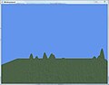 Landscape with texture.
 -
 Landscape with a different texture.


If you are interested in how your landscape looks like as a grid of triangles, go to the SetEffects() method of your Terrain.cs class and modify it like this :
        public void SetEffects()
        {
            basicEffect = new BasicEffect(graphicsDevice, null);
            basicEffect.Texture = heightMapTexture;
            basicEffect.TextureEnabled = false;
            graphicsDevice.RenderState.FillMode = FillMode.WireFrame;
        }
-
 Landscape as grid.
 -
 Closer zoom on the landscape.


Now you can easily replace your whole landscape by simply using a different HeightMap. Same applies for the texture. Just use the new names of your new images as parameters in the SetHeightMapData() method in your Terrain.cs class.
landscape.SetHeightMapData(Content.Load<Texture2D>("heightMap"), Content.Load<Texture2D>("heightMapTexture"));
Related topics
Unfortunately the Basic-Shader from XNA (BasicEffect) can handle only one texture. To improve your landscape you could now write your own EffectShader file which would handle more than one texture. If you are interested in shaders check Game Creation with XNA/3D Development/Shaders and Effects. You could make your landscape more interesting using multitexturing.
It is also possible to create a landscape using a 3D Modeling Software and import it as .x or .fbx file. Doing so will require more CPU-Power and knowledge of 3D Modeling Software though. Check Game Creation with XNA/3D Development/Importing Models.
Another really complex topic would be collision detection for an object moving on the surface of your landscape. Check Game Creation with XNA/Mathematics Physics/Collision Detection. A short introduction using the image below.

The blue circle is the object (maybe your game character). This object always has to request the y-position of you landscape for the direction it is moving in (green line). To get a smooth movement when the altitude of your landscape changes you need to interpolate (Wikipedia: Interpolate) the y-value of your object’s vector at its current position with the new y-value of your landscape’s vector (the destination). The y-value of the landscape in the image changes from 15 to 23.
You can find more on this topic and some code here:
Collision Series 4: Collision with a Heightmap
Collision Series 5: Heightmap Collision with Normals
Links
- http://en.wikipedia.org/
- http://www.riemers.net/eng/Tutorials/XNA/Csharp/Series1/Terrain_from_file.php
Literature
- Microsoft XNA Game Studio 3.0, Chad Carter
- Microsoft XNA Game Studio Creator’s Guide Second Edition, S. Cawood and P. McGee
- Spieleprogrammierung mit dem XNA Framework, Hans-Georg Schumann
Authors
RayIncarnation
3D Engines
Examples for engines allowing to simplify creation of 3D games. Should include a short intro of the engine, its capabilities, its support, maybe example projects that use it. Example for 3D engines can be found here: http://forums.create.msdn.com/forums/t/12882.aspx
QuickStart Engine

QuickStart Engine is a 3D Game Engine for XNA that allows developers to get started with 3D game programming as quickly as possible.[1]
The current version is 0.262. It is still in an beta state. The Engine is published under the Ms-PL, which makes it free to use.
Includes a physics engine, in-game GUI framework, shadow mapping, normal mapping, multi-texture splatting for terrain, and more.
Pre-Requirements
- Visual Studio 2010
- XNA Game Studio 4.0
How to get started

The concept of the QuickStart Engine is easy to understand.
A game is made out of scenes. Those scenes are stored in the SceneManager, which is part of the game class "QSGame". The SceneManager is responsible for loading and holding the current scene.
A scene is made out of entities. Every object in a scene is an entity! It can be a camera, terrain, light, player and anything else.
An entity only contains basic information like position and rotation. To give it something like a model or camera you have to add Components.
Components are bound to entities and are responsible for things like holding the model, handling input or emitting light.
Another important fact is that each entity has to be added manually to the SceneManager of your game!
The engine has also a message system, which allows every part of the game to send and listen to requests. Those requests can include things like a change of the current camera an input or a movement.
How to implement the Engine in your Project
- Go to http://quickstartengine.codeplex.com/ and download the latest version (this tutorial is based on V0.26).
- As you may wish to make changes to the engine (mind the licence!) you should copy the folder "QuickStart Engine v0.26\framework\code" into your project folder.
- For a better understanding rename "code" to something like "QS" or "QuickStart"
- Now open your projects solution file with VS2010
- Open the Solutions-Explorer, right-click your solution and click "add existing project".
- Depending on the platform you are planning to program for, choose from each folder in "QS" the csproj/vsproj-file (if there is no specific Windows/XBox project file take the general one.
- Now do the following in your XNA project
- Go to '<yourXnaGame> -> references' and add references to all projects of your solution
- In the references at 'Content' add "QuickStart_>Windows/XBox>" and "QuickStart.ContentPipeline"
- In your Game.cs ...
- add "using QuickStart;"
- make your game to a subclass of QSGame.
Et voilá! Your game is now based on the QuickStart Engine!
How to Create a Scene:
While the game gets initialised all scenes have to be created and added to the SceneManager. You have to do that in the LoadContent method of your game.
protected override void LoadContent()
{
    base.LoadContent();
    //create and load all scenes here
    Scene newScene = new PlayScene(this);
    Scene anotherScene = new AnotherScene(this);

    this.SceneManager.LoadScene(newScene, true);
    this.SceneManager.LoadScene(anotherScene, true);
    //choose the currently active Scene
    this.SceneManager.ActiveScene = newScene;
}
When a scene gets initialized it can load everything it might need later, including models, textures, images, etc. Although, assets can be loaded at any time if you'd like.
UPDATE: It should be noted that loading entities into your scene has been greatly simplified since this review was originally done. Here's documentation on how to load entities and components without using any C# code, you can now define your entities entirely from XML. http://quickstartengine.codeplex.com/wikipage?title=Creating%20Entities%20and%20Components%20with%20XML
How to Create a Terrain:
This one is a bit tricky.
Make sure to have in your Content folder a "Material\Terrain.qsm". The best is to get the file from the test project, which came with the engine. You can find it at this path: "QuickStart Engine v0.22\framework\test\QuickStartSampleGame\Content\Material".
When you have added the file to the Project, you might have to change the Importer and Processor in Properties to "QuickStart Material Importer/Processor".
We'll have another look at this file later.
To create a terrain you will need a grey scale heightmap. It has to be quadratic and the length of a side must be a power of 2 (2,4,8,16,32,64,...).
Now it is quite easy to create the terrain in a scene:
//create Terrain
Terrain terrain = new Terrain(game, QuickStart.Graphics.LOD.High);
terrain.Name = "MyTerrain";

//set the elevation strength and load the heigtmap
terrain.ElevationStrength = 75;
terrain.Initialize("./Images/heightmap", 1, 4);

//add physic to terrain
PhysicsComponent tf = new PhysicsComponent(terrain, terrain.heightData, terrain.ScaleFactor);
//add the terrain (which is derived from BaseEntity) to the SceneManager of your game
game.SceneManager.AddEntity(terrain);
}
Now there is only one thing missing! You have to add a texture map for your terrain. This map has to be of the same size as the height map and uses three colors to define the textures for the ground.
red   (255,0,0) = rocks
green (0,255,0) = grass
blue  (0,0,255) = water
Have a closer look at the "Terrain.qsm". You will find a path for the "TEXTURE_MAP". Change it to where ever you put your image. To create the map you can use any image processing software. Save it in a lossless format like "png".
How to create an Entity:
Everything in your scene is derived from BaseEntity. Whenever you want to create an object you have to start by creating a BaseEntity-object.
The entity for itself is nothing visible. You have to add a RenderComponent where you set the model and a material. In case you want collision detection and/or physics for your entity you can add a PhysicsComponent. Here is an example for a simple sphere.
//BaseEntity(your game,position, rotation, scale)
BaseEntity sphere = new BaseEntity(this.game, new Vector3(500, 100, 510), Matrix.Identity, 5f);
sphere.Name = "sphere";
//RenderComponent(parent object, path to model, path to material)
RenderComponent r = new RenderComponent(sphere, "Models/unit_sphere", "Material/SimpleColored");
r.modelColor = Color.Orange;
(((Physicscomponent(parent object, type of collider, density, reacts to forces)
PhysicsComponent p = new PhysicsComponent(sphere, ShapeType.Sphere, 5,true);
//add the entity to your games SceneManager
game.SceneManager.AddEntity(sphere);
How to add a third person Camera:
Every object can be used as a camera, which is useful for things like first person views or security cameras.
For the third person view we need a new BaseEntity and add a CameraComponent to it. We also add the ArcBallCameraInputComponent to it, which allows us to rotate the camera later. After this you have to add the camera to the SceneManager, because we have to send some messages, which will just work, when the camera is already known by the game.
BaseEntity cam = new BaseEntity(game,new Vector3(20,0,20),Matrix.Identity,1);
//CameraComponent(object, Field of View,screen width, screen height, near plane, far plane)
CameraComponent camComp = new CameraComponent(cam, 60f, game.Settings.Resolution.X, game.Settings.Resolution.Y, 0.5f, 1000);
//add the input component
ArcBallCameraInputComponent thirdPersonCam = new ArcBallCameraInputComponent(cam);

game.SceneManager.AddEntity(cam);
- The first message is, to say, that this is from now on the main camera
MsgSetRenderEntity RndMsg = ObjectPool.Aquire<MsgSetRenderEntity>();
RndMsg.Entity = cam;
this.game.SendInterfaceMessage(RndMsg, InterfaceType.Camera);
- The second message sets the player object as the parent
MsgSetParent msg = ObjectPool.Aquire<MsgSetParent>();
msg.ParentEntity = playerEntity;
msg.UniqueTarget = cam.UniqueID;
game.SendMessage(msg);
- The third message is to say that the player rotates with the camera
MsgLockCharacterRotationToCamera msg = ObjectPool.Aquire<MsgLockCharacterRotationToCamera>();
msg.UniqueTarget = player.UniqueID;
msg.LockRotation = true;
game.SendMessage(msg);
Finally you have your camera always in a third person view behind your player!
How to create a Character Object
The third person camera has no use as long as we don't have a player. Most of the script you will already recognize from the examples before.
BaseEntity player = new BaseEntity(this.game, new Vector3(500, 100, 500), Matrix.Identity, 1);
player.Name = "player";

RenderComponent comp = new RenderComponent(player, "Models/unit_sphere", "Material/SimpleColored");
//you can set whether an object receives and creates shadows
comp.SetShadowingProperties(true, true);
comp.modelColor = Color.Blue;

//The engine already has special physics and an input component for a player
CharacterPhysicsComponent newPhysComponent = new CharacterPhysicsComponent(player, ShapeType.Sphere, 5.0f);
CharacterInputComponent input = new CharacterInputComponent(player);

game.SceneManager.AddEntity(player);

//Tell the game, that this is the controlled object
MsgSetControlledEntity msgSetControlled = ObjectPool.Aquire<MsgSetControlledEntity>();
msgSetControlled.ControlledEntityID = player.UniqueID;
this.game.SendInterfaceMessage(msgSetControlled, InterfaceType.SceneManager);
How to create a Light:
The last thing we need for a basic scene is a light.
Every Entity can emit light. Therefore you just have to create the lights settings, a LightEmitterComponent and initialise it after adding it to the SceneManager. This could look like this:
BaseEntity light = new BaseEntity(game, new Vector3(0, 500, 0), Matrix.CreateRotationX((float)Math.PI/2f), 1);
light.Name = "light";

LightSettings s =  new QuickStart.EnvironmentalSettings.LightSettings();
s.LightDirection = Vector3.Down;
s.AmbientColor = new Vector4(1f, 0f, 0f, 0f);
s.DiffuseColor = new Vector4(0f, 1f, 0f, 0f);
s.SpecularColor = Vector4.Zero;
s.MinimumAmbient = 50f;
s.SpecularPower = 10f;

LightEmitterComponent lc = new LightEmitterComponent(light, s);
game.SceneManager.AddEntity(light);

lc.InitializeLightDirection();
Review
The QuickStart Engine has potential but it takes some time to understand what's going on. In some points it is a bit to static and needs to be improved.
The engine was updated to work with XNA 4.0, also loading of entities and components is much simpler now and can be done entirely through XML. Also other features like texture mapping for models and in-game GUI have been added since this review was done.
References
- ↑ http://quickstartengine.codeplex.com/ - homepage of project
Authors
juliusse
Networking and Multiplayer
Introduction
Playing along can be fun, but playing with others is even better. But for this you need to learn about techniques such as split-screen and networking. Also some network engines will be introduced in this chapter.
More Details
Lore ipsum ...
Split-Screen
The simplest way to create a multiplayer game is the split screen. For two players that means that the screen (TV) is split in half (vertically or horizontally) and one displays the view for player one, and the other the view for player two. Since you can connect up to four gamepads to an XBox, hypothetically, up to four players could play this way.
Authors
none
Network and Peer-to-Peer
well, I will do that. - project79
Basics
One very important point is: decide for or against networking support of your game right from the beginning. Due to some horrible stuff like bandwidth, latency, packet loss and also all these together, you can't send just your input over the wire. There will be failures you have to hide before the player. Why, which failures and how will be mentioned later. First there is some theory on games and networks.
Game Types
Network architectures
Peer-to-Peer

Most people think on illegal stuff hearing peer-to-peer - or short p2p. But it isn't illegal. It's only a way of organizing a network.
Here every machine (called peer) knows every other or at least every other peer it wants to communicate with. Thus one peer can directly communicate with another which is faster than the client/server approach. Also you don't have one machine with the need of a lot of bandwidth. But temper the wind to the shorn lamb. The peer with the poorest bandwidth determines the speed for all other peers (for the connections with him). (Everybody is connected to everyone. Thus the download of B is the same as the upload of A)
If every peer is equal, nobody has more than the others, also the logic. So everybody is calculating his part of the world and therefore cheating is easy - nobody (can) controls you. Another disadvantage is the way of finding other peers. The player can't type in 10 IP-Addresses and you can't scan the whole net.
further reading at Wikipedia
Client/Server

This is the typical network architecture in the net. Here every machine (client) is connected to one machine (the server) in the middle. Normally the flow of information is that the clients are sending there input to the server, which computes the results and send them back. So the logic is on one central point and can't be manipulated by a player. Therefore cheating is hard. There is also the advantage of creating a gamesession, because the clients only need the address of one machine.
But there are also cons. Due to everybody is communicating via the server, the bandwidth load is much higher on this machine. Also this machine should be more powerful. Another point is latency. Every message has to be passed by the server, which leads to a longer distance and more time for delivery.
further reading at Wikipedia
Hybrid
Like hybrids always are, there are somehow both. Here client/server and p2p. Following two interesting kinds are mentioned.
The first deals with the problem of finding other peers. Somehow you need a central point like the server. So why not using one? One player starts a multiplayer session and in background a little server. The others only joins a session. Maybe they type in the IP of the first player or in a LAN the game looks for the server. Having found the server and set a flag for being ready, the IPs of all clients and some initializing stuff (the map, rules for this session) are shared. Now every client could address every other client. Thus the server is stopped, the network becomes p2p and the game starts.
The second deals with the problem of cheating. Due to every peer having the whole logic (and using it) there is no authority machine which could say that the conclusion of A is wrong. But having one big authority machine controlling the logic, would be client/server, which maybe is impossible for bandwidth reasons. So split up the logic (for important parts) in small independent parts and distribute them on the peers. Thus A controls the teamflag, while B controls something else and so on.
Techniques
Limits
Bandwith
There are typical 12 to 250 kilobytes per second available. But the recommendation is to use only 8 kilobytes per second. That is the bandwith 99% of the user have (data collection during Halo 3 beta (2007)[1] (median for up is 44 and downstream 42)
So why only that little?
Services providers always want to sell their products. Even on good moments you wont have the full power which is written on your contract. The bandwidth is influenced by the numbers of people online, your distance to the router, the activity of the others and so on. And maybe your teammate hasn't a good connection. But his upload is your download and vice versa. That is also the reason for the upstream being similar to the downstream.
Latency (one way)
Ok. Physics.
We all know the speed of light is 299,792,458 metres per second in vacuum. We also know that packets are send via light or electricity. But is there vacuum in these cords? No, it is fiber or copper, slowing our packets down to 194,865,097 m/s (65%). So here are some distances from Berlin to other locations and the time each packet took (theoretic and round-trip; the website-hoster are only in the near of the cities)
| City | Distance (km) | calculated time (ms) | measured time (ms) (ping 32 byte) |
|---|---|---|---|
| London | 910 | 4.67 | 137 (www.proteusinvestigations.co.uk) |
| Pretoria | 8,660 | 44.41 | 272 (mybroadband.co.za) |
| Mexico City | 9,710 | 49.79 | 671 (mexicocity.gob.mx) |
| Sydney | 15,960 | 81.85 | 432 (cityofsydney.nsw.gov.au) |
So why is the measured time always that much higher? Because you don't have a direct (physical) connection to these computers. The packets have to be routed and each router needs some time to put your packet on the right line (5–50 ms). Also your modem adds 10 ms.
So a good number for latency in games is 270 ms.
Packet loss
This issue (which is also known as "bad latency") comes down to a question of which protocol you use for your packets. For Games, UDP is the primary protocol used, but this isn't always reliable. UDP Protocol fires the packets down the wire and forgets them. Thus if a packet gets lost, it can't be found again. In real-time tests, 2% packet loss is the average latency, but for games, be ready to account for up to 10% packet loss. The possible corruption of each packet is also a distinct possibilty, along with the correct order of the stream being jumbled up and incorrect. Another protocol, TCP, fixes most of these issues, but is too slow to make a big difference. A good use of TCP in multiplayer gaming in in a turn-based game or another environment where latency is not a big issue.
What to do
Compression
Whatever you are programming, one point you should think about: use the right (smaller) data type. A byte is only a quarter of an int. And matricies can be represented as a quaternion and a vector, which leads to 7 values instead of 16. Due to their overhead strings should be avoided. You could also put several booleans in one bitfield (ok, that isn't really smaller), but you putting several numbers (which aren't 32 bits long) in one 32 bit Integer (via bitshifting).
Another way is not to send the whole world everytime (or the specific state of your character), just send the changes.
Don't be too exact! Think on images, there you don't send the real value of every pixel. Besides of grouping pixels the values are quantized. So instead of sending the exact angle in radians (or degrees) turn in into degrees and round the values to natural numbers. Or you turn them into a byte if 256 different values are still enough.
Others and more XNA/C# specific possibilities are:[2]
- if an float-value can't be greater than 1 turn it into an Alpa8 (75% less)
- if a float-value can be greater than 1 turn it into a Halfsingle (50% less)
- Vector2 ⇒ HalfVector2
- Vector4 ⇒ HalfVector4
- if a Vector3 is normalized ⇒ Normalized101010
- if not ⇒ 3 HalfSingle
- Quaternion ⇒ NormalizedByte4
- Color.packedValue
Fewer Packets
Just a simple example. You have a small game with 8 players which runs at 30 fps. Each player has a position, a direction where he look at and a bool as some kind of status. Every frame you send your data to all other players.
But aren't we sending over the internet? So we need at least three things more.
The IP header is 20 bytes, UDP 8. That's the transport, but somehow the other computer have to know, how to deal with the package. So there is still the header of our framework missing. Live needs 16 bytes and something around 7 bytes is needed for XNA. Thus we have 51 additional bytes not storing any data.
Ok. 15.6 kB that is twice our limit of 8. If you want to send your voice via XNA you need to add 500 bytes per second for each teammate.
In the example we have 25 Bytes of (for the game) useful data and 51 Bytes overhead, which means that 67% of the used bandwidth we have filled with “waste”. This waste we can not shrink absolutely, but relatively. If we reduce the number of sendings to every third frame (10 times per second, typical is 10 to 20 times). Let's assume we would still send our data of this frame. Hence we would send only 5.2 kB of data, but we still have had an overhead of 67% and fewer useful data. So we combine the last 2 frames with our “sending” frame. To make it easier we send only the whole position and direction of us in every of these frames – better would be to send the position of the first frame and for the second and third in smaller datatypes (the same for the direction).
75 bytes useful data vs. 51 bytes overhead means only 40% waste with exactly the same data. Sounds great and we are still sending our whole world to everyone uncompressed.
Just a comparison of roundtrips. First I ping my website with a packet size of 5250 Bytes, afterwards I use 15960 Bytes. See the results:


| minimum | maximum | average | |
|---|---|---|---|
| 5250 Bytes | 110 | 255 | 140 |
| 15960 Bytes | 217 | 317 | 264 |
I think I haven't to explain, that more data also mean more latency.
Don't send unneeded data
Think about these questions:
- To whom I have to talk during the game?
- Does I have to know what is behind me?
- In which direction bounce the dust particles?
- Where are which star?
- Need Linus to know which boots I wear or where I look at?
- ...
Ok. About some thinks you will have lost some thoughts and on others maybe only a „What the ….“ The last type of question you can forget, if you still have in mind, that not every client have to have the same world, but one which is similar enough to the other ones. The rest should be prioritizes.
Prediction & Smoothing
This is not that easy in a lot of cases. But the underlying thought is. Playing your game, it already has some data of your teammates. Even if they are from the past, you can combine them to compute their way of moving. This is prediction, smoothing now deals with the failures which has been made. Because showing the original position instead of the prediction when there are a new packet isn't that nice (the avatar would jump). That's why it is so difficult.
But you can make it a little bit easier by separating the physic state of an object from the rest of its states and put it (with all stuff the physicsimulation needs) in a nested helper structure. Also send more data for the simulation. More (and the right) data leads to a better prediction. Thus the data has to be send less frequently.
Due to the fact, that the position of an enemy is only a prediction or a smoothing of it and "reality" the player can't really rely that his enemy is where he sees him – remember we live in parallel worlds where some things are known to be different and others are only guessed. So when you throw a book to a specific position, the other guy could be a little bit to the left in his world and so you miss him. Therefore it is better throw at this guy and let your computer compute whether you hit him or not - and how you missed him.
You also have to hide the roundtrip time to the server (or other peers) responding on the players behaviour. That is easy, hide it with an animation. Let the character say something or let him look around like searching the path. You can also use it to be in sync with other players.
Weblinks
References
- ↑ some parts can be found here on slide 18 and 20 Networking, Traffic Jams, and Schrödinger's Cat
- ↑ Chad Carter - Microsoft XNA Game Studio 3.0 unleashed - p.561
Network Engines
Other useful looking Engines:
- WCF - Windows Communication Foundation
- XNA integrated
- RakNet
Other interesting facts and examples can be found here: http://create.msdn.com/en-US/education/catalog/?devarea=19 , especially the one called Network Prediction.
Lidgren Network Engine
The Lidgren network engine is a .NET-based library made by Michael Lidgren. It can basically be used with every kind of .NET-Application. For delivery it uses a single udp socket and comes with classes for peer-to-peer and server-client connections. The engine runs under the MIT License, which makes it free to use. The current Version “gen3” requires .NET 3.5 or higher. Lidgren comes with an additional library that contains extension methods for some classes for a better XNA-Support. However you cannot use Lidgren for Xbox games.[1]
Important Classes
NetPeer
NetPeer represents the local connection point. It holds and creates connections to other peers. Important derived classes are NetServer and NetClient, which contain appropriate modifications for a server-client-system.
NetOutgoingMessage
An Object of this class is the carrier for your information. To create one, you have to use the CreateMessage()-method of your NetPeer object. With Write() you can put all your data into the message. Write() accepts all primitive types and objects.
NetIncomingMessage
This is used to hold the information about a received message. Additional to the content it says something about the MessageType, which can be library-related or data you have sent. *List of MessageTypes*
NetConnection
Represents the connection to a remote host.
Implementation
How to get started
- Download the latest version from the project's website.
- Open the "Lidgren XNA Extensions/Lidgren XNA Extensions.sln"-file and compile the solution.
- Copy the created .dll-files in your project folder and reference to them within your project.
- Now you should be able to use the Lidgren.Network namespace.
How to create a Peer
class Program
{
    //hold the NetPeer Object as a member
    //In this example I use a server, because it is more common to work with server and clients
    private NetServer server;

    public Program()
    {
        //When initialising, create a configuration object.
        NetPeerConfiguration config = new NetPeerConfiguration("Server");

        //Setting the port, where the NetPeer shall listen.
        //This is optional, but for a server its good to know, where it is reachable
        config.Port = 50001;
        //Create the NetPeer object with the configurations.
        server = new NetServer(config);
        //Start
        server.Start();
    }
}
How to send a message
//get a message from the servers message pool
NetOutgoingMessage msgOut = server.CreateMessage();
//write your data
msgOut.Write("Some Text");
msgOut.Write((short)54);
//send the message to a client
server.SendMessage(msgOut, client, NetDeliveryMethod.ReliableOrdered);
The different NetDeliveryMethods are explained here
How to receive a message
//use local message variable
NetIncomingMessage msgIn;
//standard receive loop - loops through all received messages, until none is left
while ((msgIn = server.ReadMessage()) != null)
{
    //create message type handling with a switch
    switch (msgIn.MessageType)
    {
        case NetIncomingMessageType.Data:
            //This type handles all data that have been send by you.
            break;
        //All other types are for library related events (some examples)
        case NetIncomingMessageType.DiscoveryRequest:
            //...
            break;
        case NetIncomingMessageType.ConnectionApproval:
            //...
            break;

    }
    //Recycle the message to create less garbage
    server.Recycle(msgIn);
}
A description for all MessageTypes can be found here
How to connect to a server
[2]
The first step is to enable three specific message types.
//for the server
serverConfig.EnableMessageType(NetIncomingMessageType.ConnectionApproval);
serverConfig.EnableMessageType(NetIncomingMessageType.DiscoveryRequest);
//for the client
clientConfig.EnableMessageType(NetIncomingMessageType.DiscoveryResponse);
After initialising the client you can search for the server. Therefore, you can send a request to an ip address or search all systems in your local network.
//search in local network at port 50001
client.DiscoverLocalPeers(50001);
The server has now received a DiscoveryRequest which has to be handled by the "receive message loop"
case NetIncomingMessageType.DiscoveryRequest:
    NetOutgoingMessage msg = server.CreateMessage();
    //add a string as welcome text
    msg.Write("Hellooooo Client");
    //send a response
    server.SendDiscoveryResponse(msg, msgIn.SenderEndpoint);
    break;
The Client has now received a DiscoveryRequest by the server. Assuming there is just one server in your local network you can simply connect to it.
case NetIncomingMessageType.DiscoveryResponse:
    Console.WriteLine("Server answered with: {0}", msgIn.ReadString());
    client.Connect(msgIn.SenderEndpoint);
    break;
The last step is to receive the ConnectionApproval message at the server and to approve the connection.
case NetIncomingMessageType.ConnectionApproval:
msgIn.SenderConnection.Approve();
break;
Raknet
RakNet is a library with several classes to perform networking solutions and developed by Jenkins Software LL. It is a cross-platform for C++ and C#. Therefore, it can be used on all major platforms, including Android and iOS. Main features are object replication, lobby system, secure connections, voice communication and an autopatcher.[3]
Swig
Swig can be used to generate wrapper code for a native DLL allowing to use RakNet in C#.[4] Swing generates CXX and .h files that represent the interfaces as well as inclusions for the C# project to connect to the DLL. How to use Swig see the detailed description.
Important Classes
RakPeerInterface
Even though RakPeerInterface is not an actual class it is the main interface for the network communications and the responsible for the startup. An instance of a peer is return by calling the .GetInstance() method.[5]
SocketDescriptor
An instance describes the local socket which can be used for the startup.[5] It is possible to define the port with parameters or use 0 to automatically pic a free port. In addition if desired an array of socket descriptors can be made.[6]
Packet
It represents a message from another system/computer and contains information about the message, such as length, bit size or id of sender.
Implementation
=====Connection as Client===== [7]
using UnityEngine;
using System;
using System.Collections;
using RakNet;
public class ConnectClient {
public static string remoteIP = “127.0.0.1″;
RakPeerInterface myClient;
SocketDescriptor scktDist;
//…
void Awake() {
myClient = RakPeerInterface.GetInstance();
scktDist = new SocketDescriptor();
// Prameters: 1) max. number of connection 2) SocketDescriptor to specifie ports/addresses
myClient.Startup(1,scktDist,1);
}
void OnGUI(){
//…
// if not yet connected
myClient.Connect(remoteIP, 25000, “”,0);
//…
}
}
===== Connection as Server=====[8] Starting a server is very similar to the instructions above.
public class ConnectServer {
public static string remoteIP = “127.0.0.1″;
public static int maxConnectionsAllowed = 4:
public static int maxPlayersPerServer = 10;
RakPeerInterface server;
SocketDescriptor scktDist;
//…
void Awake() {
server = RakPeerInterface.GetInstance();
scktDist = new SocketDescriptor();
server.Startup(maxConnectionsAllowed, 30, scktDist, 1);
server.SetMaximumIncomingConnections(maxPlayersPerServer);
}
}
===== Reading of Packets=====[8] Remarks, Ii a packet is 0 nothing is to read.
public class PackageReading {
RakPeerInterface server;
Packet p;
//…
void Reading() {
while (true) {
if (p = server.Receive()) {
// do something terribly interesting with p...
}
}
}
}
===== Sending of Packets=====[9] Remarks, it is used BitStreams to create the "packets".
public class PackageReading {
RakPeerInterface peer;
Packet p;
//…
void Sending() {
MessageID useTimeStamp; // Assign this to ID_TIMESTAMP
Time timeStamp; // Put the system time in here returned by GetTime()
MessageID typeId; // This will be assigned to a type I've added after ID_USER_PACKET_ENUM, lets say ID_SET_TIMED_MINE
useTimeStamp = ID_TIMESTAMP;
timeStamp = GetTime();
typeId=ID_SET_TIMED_MINE;
BitStream message = new BitStream();
message.Write(useTimeStamp);
message.Write(timeStamp);
message.Write(typeId);
message.Write("Hallo",5);
peer = Send(BitStream * bitStream,HIGH_PRIORITY,RELIABLE,0,UNASSIGNED_SYSTEM_ADDRESS,true);
}
}
Links
Windows Communication Foundation
The Windows Communication Foundation (WCF) from Microsoft is a platform or application programming interface that bundles several technologies for building connected services or programs. Microsoft defines its features: orientation, interoperability, multiple message patters, service metadata, security and AJAZ and REST support.[10] It supports SOAP over HTTP, TCP, Message Queues, etc. WCF requires Windows XP SP2 or higher.[11]
References
- ↑ http://code.google.com/p/lidgren-network-gen3/ - project page at google code
- ↑ http://www.xnamag.de/article.php?aid=19#chapter3 - article about connections between server and clients
- ↑ http://www.jenkinssoftware.com/
- ↑ http://www.jenkinssoftware.com/raknet/manual/swigtutorial.html
- ↑ a b http://www.jenkinssoftware.com/raknet/manual/Doxygen/
- ↑ http://www.jenkinssoftware.com/raknet/manual/startup.html
- ↑ http://txcom2003.wordpress.com/2011/05/29/unity-3d-and-raknet-4/
- ↑ a b http://www.jenkinssoftware.com/raknet/manual/detailedimplementation.html
- ↑ http://www.jenkinssoftware.com/raknet/manual/creatingpackets.html
- ↑ http://msdn.microsoft.com/en-en/library/ms731082.aspx
- ↑ http://msdn.microsoft.com/de-de/library/ms733890.aspx
Authors
mglaeser and juliusse
Artificial Intelligence
Games always provided an environment for developing artificial intelligence. So in the last decades it became one of the most important components of games. Nowadays games that have sophisticated AI are state of the art. Some simpler and some more sophisticated algorithms you will need in many games. It is used in many situations, some are:
- control of NPCs
- pathfinding
- dynamic game difficulty balancing
- combats / fights
History
Already in the very beginning of game development, in the 1970s, programmers and developers came face to face with the field of game artificial intelligence. But at this time AI was simple and so to say humble and that status didn’t change until few years ago.
- "AI has been quietly transformed from the redheaded stepchild of gaming to the shining star of the industry" - Steve Rabin, AI Game Programming WISDOM, 2002, p. 3
The first games featuring a single player mode and therefore AI in its very beginning like the Atari game “Qwak!” didn’t have AI like we would describe it today. Enemy movement was mostly predefined and stored as patterns. Only with the improvement of the hardware like the incorporation of microprocessors, that allowed way more computation, further random elements could be implemented. Games resulting from that were for example Space Invaders, Galaxian, and Pac-Man. Those games presented e.g. an increasing difficulty level, complex and varied enemy movements, events depending on the players input and even different personalities for each enemy. Along with the loom of new game genres in the 1990s new AI tools were developed and used. Among these tools were for example finite state machines. In the newer games AI became the main aspect of game. The improvement of AI didn’t only depend on the given hardware components. Well, in fact it definitely was a very important aspect. There were some problems that couldn’t be solved without significant processor resources. But it should be added that in the beginning of game development programmers simply didn’t take AI overly serious. Mostly AI was done in the very end after completing all the high-priority tasks.[1]
- Today AI climbed up the games ladder to be the highest-priority task.
Difficulties
AI has to be calculated live (during the game), therefore (good) performance is very important to let the game run smoothly. To ensure that there are many simplifications, workarounds, cheats in the algorithms which approximate the ideal behaviour of the player. So they are fast and intelligent at the same time. When performance is an important issue, it is clear that stuff like bruteforcing all possible decisions is not the best way to deal with such situations in game AI.
Another essential fact is that the computer player should not play perfect even if he could. Cheating is a big word in that topic, because the computer knows all facts and has all kinds of information about the game world so it would be possible to let the AI player know things they realistically could not know. The player has to think he plays against a real enemy and not a computer, that is why firstly the AI has to be beatable (not invincible) and furthermore it has to act human-like (do mistakes, act randomly in some situations, etc.). If the AI does not behave in this way the game would be soon very boring for the player or just frustrating if he has no chance to win. Some games use approximation algorithms instead of perfect solutions and implement "wrong" (or worse) decisions in their algorithms.
- half-dozen rules of thumb and heuristics, just enough to give a good gameplay experience
References
- ↑ Steve Rabin (2002). AI Game Programming Wisdom. Cengage Learning.
Authors
- iSteffi
- LWAGNER
Games always provided an environment for developing artificial intelligence. So in the last decades it became one of the most important components of games. Nowadays games that have sophisticated AI are state of the art. Some simpler and some more sophisticated algorithms you will need in many games. It is used in many situations, some are:
- control of NPCs
- pathfinding
- dynamic game difficulty balancing
- combats / fights
History
Already in the very beginning of game development, in the 1970s, programmers and developers came face to face with the field of game artificial intelligence. But at this time AI was simple and so to say humble and that status didn’t change until few years ago.
- "AI has been quietly transformed from the redheaded stepchild of gaming to the shining star of the industry" - Steve Rabin, AI Game Programming WISDOM, 2002, p. 3
The first games featuring a single player mode and therefore AI in its very beginning like the Atari game “Qwak!” didn’t have AI like we would describe it today. Enemy movement was mostly predefined and stored as patterns. Only with the improvement of the hardware like the incorporation of microprocessors, that allowed way more computation, further random elements could be implemented. Games resulting from that were for example Space Invaders, Galaxian, and Pac-Man. Those games presented e.g. an increasing difficulty level, complex and varied enemy movements, events depending on the players input and even different personalities for each enemy. Along with the loom of new game genres in the 1990s new AI tools were developed and used. Among these tools were for example finite state machines. In the newer games AI became the main aspect of game. The improvement of AI didn’t only depend on the given hardware components. Well, in fact it definitely was a very important aspect. There were some problems that couldn’t be solved without significant processor resources. But it should be added that in the beginning of game development programmers simply didn’t take AI overly serious. Mostly AI was done in the very end after completing all the high-priority tasks.[1]
- Today AI climbed up the games ladder to be the highest-priority task.
Techniques
There are countless in-game scenarios crying for artificial Intelligence. So how do you solve chasing, flocking or path finding? Smart programmers and developers puzzled out some clever techniques and algorithm giving your games a touch of brain. Some interesting algorithms and AI situations I will explain in the following. I won't assert a claim to a complete list. But I will present you the basic scenarios you will be faced with. [2]
Chasing and Evading
No matter what kind of game you have chances are that you will be faced with chasing and evading.
Basic Algorithm
The simplest way to describe chasing and evading in form of an algorithm is to firstly find out the distance between predator and prey and than in case of chase decrement it and in case of evade increment it.
| Chase | Evade |
|---|---|
if (predatorPos > preyPos)
predatorPos --;
else if (predatorPos < preyPos)
predatorPos ++;
|
if (preyPos> predatorPos )
preyPos++;
else if (preyX < predatorPos )
preyPos-- ? > ;
|
Well it works but clearly that is not a very natural approach.
Line-of-Sight Chasing
Way more realistic is to let the predator take a straight line towards the prey.

The algorithm for finding the direct way is a little more complicated. You need to find the direct and shortest way without unnecessary steps between predator and prey. Out there are a lot of useful algorithms that could help us out with our problem. Think about those line drawing algorithms build for a pixel environment. Those algorithms are built for finding a direct way from a starting point to a destination. But another criterion our algorithm has to fulfill is to find the shortest way. So it is time to ask Bresenham. Bresenham’s algorithm offers us what we want. Here you are.
Intercepting
Even more effective for the predator could it be for it to intercept the prey at some point along the prey’s trajectory.

The intercepting point should be selected depending on the relative positions and velocities of predator and prey. To predict that point you have to consider three values. Those are position, direction and velocity.
Calculation steps
- Relative velocity (closing velocity)
- Relative distance (range to close)
- Time it will take to travel the relative distance at a speed equal to the closing speed (time to close)
- Predicted position of the prey (target point)


Vector FindInterceptingPoint(void)
{
Vector v, d;
Double t;
v = Prey.v - Predator.v; // closing velocity
d = Prey.pos - Predator.pos; // range to close
t = d.Magnitude() / v.Magnitude(); // time to close
return Prey.pos + (Prey.v * t); // target point
}
Pattern Movement
Patterns for different movements and maneuvers are predefined. Computer controlled character using those complex patterns give the illusion of intelligent behavior. The standard algorithm uses lists or arrays of encoded instructions. These instructions tell computer controlled character how to move each step through the game loop.
Example
Following pattern was borrowed from the book "AI for Game Developers" from O'REILLY:
Pattern[0].turnRight = 0;
Pattern[0].turnLeft = 0;
Pattern[0].stepForward = 2;
Pattern[0].stepBackward = 0;
Pattern[1].turnRight = 0;
Pattern[1].turnLeft = 0;
Pattern[1].stepForward = 2;
Pattern[1].stepBackward = 0;
Pattern[2].turnRight = 10;
Pattern[2].turnLeft = 0;
Pattern[2].stepForward = 0;
Pattern[2].stepBackward = 0;
Pattern[3].turnRight = 10;
Pattern[3].turnLeft = 0;
Pattern[3].stepForward = 0;
Pattern[3].stepBackward = 0;
Pattern[4].turnRight = 0;
Pattern[4].turnLeft = 0;
Pattern[4].stepForward = 2;
Pattern[4].stepBackward = 0;
Pattern[5].turnRight = 0;
Pattern[5].turnLeft = 0;
Pattern[5].stepForward = 2;
Pattern[5].stepBackward = 0;
Pattern[6].turnRight = 0;
Pattern[6].turnLeft = 10;
Pattern[6].stepForward = 0;
Pattern[6].stepBackward = 0;
.
.
.
The instruction encoded ins this pattern are:
- move forward 2 distance units
- move forward 2 distance units
- turn right 10 degrees
- turn right 10 degrees
- move forward 2 distance units
- move forward 2 distance units
- turn left 10 degrees
Flocking
Sometimes in games it’s more realistic to let non player characters move in cohesive groups. Let’s consider birds, sheep and all these gregarious animals always hiding in the safety of their flock. Or what about those big computer controlled human, troll or orcs units. Flocking definitely is a common performance in games. See the clip side that I borrowed from roxlu here http://vimeo.com/5352863.:
Basic Algorithm
There are some basic flocking algorithms implementing our wished behavior. We will look at the Craig Reynolds algorithm. This implementation is leaderless. All individuals of the boid (term coined by Craig Reynolds referring to simulated flocks) are following the group itself.
Rules
The algorithm is following three simple rules:
- Separation
- steer to avoid hitting the neighbors
- Alignment
- steer so as to align itself to the average heading of the neighbors
- Cohesion
- steer toward the average position of the neighbors
Example
You can find an explanation of the algorithm and its implmentation here: http://oreilly.com/catalog/ai/chapter/ch04.pdf
Path finding
There are thousands of individual path finding problems. You won’t find one algorithm as sure formula for all kind of them. Even the A* algorithm – actually an ideal solutions for many problems – is not the appropriate for every situation.
Basic algorithm
The algorithms in chapter Chase and Evading do some basic path finding. We clarified that the Line-of-Sight algorithm creates a way more realistic movement. Now let’s have a look at obstacle avoidance:
Obstacle Avoidance
The easiest way to implement obstacle avoidance is the following:
if Player In Line of Sight
{
Follow Straight Path to Player
}
else
{
Move in Random Direction
}
Problem here is due to its simplicity this will only work with a few obstacles. A little more effective is it to let the character trace around an obstacle: When the character borders on an obstacle it traces around it. It stops tracing once the destination is in the characters line of sight.
Breadcrumb Path finding
Here the player itself is defining the way for the non player character. This way the computer controlled player seems very intelligent. The player is leaving markers on the road every step it takes. The non player character will only follow those footsteps.
Path Following
Path following you will need for example in a car racing game. There is no definite destination to head to. There is only a predefined road that has to be followed.
Way Point Navigation
Path finding is a very time consuming task. Especially when you have a big environment with a lot of obstacles. Waypoint reduces this problem. The main idea is it to place nodes in the game environment and then use them for inexpensive path finding algorithms.
A* Path finding
The A* algorithm provides an effective solution to the problem of path finding.
Further Techniques
We looked at a lot of gameplay situations needing an AI approach. But those aren't nearly all. If your curiosity just have a look at O'REILLY's book "AI for Game Developers"
Examples
Pong
Pong was firstly released in 1972 by Atari. It consists of a black screen with 2 paddles, one on each side of the screen, and a ball. The paddles are controlled by players who can move them up and down to fetch the ball which is moving from side to side. If one of the players misses the ball, the opponent is credited with one point. The game ends if one players reaches a fixed number of points - e.g. 10 points.[3]
AI in Pong
If you decide to play against the computer you are actually playing against an AI algorithm. You are always standing before the decision if you move your paddle up, down or not at all. And so is the computer:
1st approach
An easy solution for this problem is to analyze the current state of the ball (its position and its direction of movement) to decide which move to make with the paddle. By knowing the direction of the ball (an angle in degree) you can determine whether the ball wents up or down on the screen. The computer can now calculate the difference in the y-positions of ball and paddle and decide upon that knowledge to move the paddle down or up to decrease this difference until it is 0 in the best case. If it is nearly 0 then the paddle can stop and wait till the ball movement requires other actions to be taken.
int difference = ball.positionY – paddle.positionY;
if(difference >= 5 || difference <= -5)
{
if(difference > 0)
{
paddle.moveDown();
}
else
{
paddle.moveUp();
}
}
The benefit of this approach is that it is easy to implement. It does not need much calculation effort (good performance) and tends to do some mistakes or gets taken by surprise in some situations. There it seems more human-like and is beatable. One of these mean (for the computer AI) situations is when the paddle follows the ball up and then shortly before the ball reaches the side of the paddle it hits the upper wall and changes its direction to go down. Then it may occur that the paddle is too slow (especially with faster balls in higher levels) to react on this change in direction and loses the ball.
2nd approach
The 2nd approach is a little more sophisticated and needs more calculation. All you need is the current position of the ball and its current movement direction - that's what you can get from the game engine. Based on these values it is possible to determine the further way of the ball (including all wall collisions and direction changes) and at the end the position where it could possibly hit the paddle of the AI player. If you got this point - and this point will never change because normal pong has no suddenly occuring situations that could change the direction somehow - you just have to directly move the paddle to this point to catch the ball and kick it back in the opponents half. This approach could also be slightly modified by positioning the paddle in a way it hits the ball at the corners of the paddle to give it a little swerve.
Even if it's the more improved solution to this problem there are some disadvantages. It is more complicated to implement this algorithm, it may need longer and costs more resources to calculate the end position of the ball (maybe too long for slow systems like mobile phones, handhelds, etc.) and the most important point (in my opinion) is that you have a de facto unbeatable and perfect enemy because it always hits the ball as good as it's possible which could be annoying for a real player to compete with.
More Examples
- eliza
- tic tac toe
Difficulties
AI has to be calculated live (during the game), therefore (good) performance is very important to let the game run smoothly. To ensure that there are many simplifications, workarounds, cheats in the algorithms which approximate the ideal behaviour of the player. So they are fast and intelligent at the same time. When performance is an important issue, it is clear that stuff like bruteforcing all possible decisions is not the best way to deal with such situations in game AI.
Another essential fact is that the computer player should not play perfect even if he could. Cheating is a big word in that topic, because the computer knows all facts and has all kinds of information about the game world so it would be possible to let the AI player know things they realistically could not know. The player has to think he plays against a real enemy and not a computer, that is why firstly the AI has to be beatable (not invincible) and furthermore it has to act human-like (do mistakes, act randomly in some situations, etc.). If the AI does not behave in this way the game would be soon very boring for the player or just frustrating if he has no chance to win. Some games use approximation algorithms instead of perfect solutions and implement "wrong" (or worse) decisions in their algorithms.
- half-dozen rules of thumb and heuristics, just enough to give a good gameplay experience
References
- ↑ Steve Rabin (2002). AI Game Programming Wisdom. Cengage Learning.
- ↑ David M. Bourg, Glenn Seemann (2004). AI for Game Developers. O'Reilly Media.
- ↑ http://en.wikipedia.org/wiki/Pong
Authors
- iSteffi
General Information
Today it is a common approach to create solutions which are an overall package for specified topic. These solutions are often called engines. Every day there mushroom new ones. For example for 3D graphics, sound, network and even for artificial intelligence which is especially for games. These AI-Engines for games solve several problems, which often appear in the procedure of creating games, like pathfinding, decision making, learning, movement, tactical and steering behavior, etc. So there are even several AI-Engines and libraries which provide some of those algorithms. These give you the ability to make your games more intelligent and challenging.
Available AI Engines for XNA
SharpSteer
SharpSteer by Bjoern Graf and Michael Coles is a C# portation of OpenSteer(C++) which is an open source library to help construct steering behaviors for autonomous characters in games and animation and it is distributed in accordance with the MIT License [1]. Its last release was in March 2008 and it is designed for XNA 2.0, but it also works at 3.1. There is a demand to port it on XNA 4.0, but the conversion has not happened yet [2]. As the name implies SharpSteer's responsibility relies on steering behaviors like cohesion, separation, alignment and many more. Its actual version includes a demonstration of 200 simulated flocking bird like objects which are also called boids [3]. In SharpSteer boids can be everything (a football player, an enemy soldier, a car) in a game. It must at least have the SharpSteer's interface IVehicle. The most important class is the SteerLibrary.cs. It is the heart of SharpSteer which consists the main algorithms for the steering behavior:
- The alignment behavior: Move in the average direction of other nearby vehicles

If there is another vehicle in the light blue area, it will affect this white vehicle.[3]

// Alignment behavior
public Vector3 SteerForAlignment(float maxDistance, float cosMaxAngle, List<IVehicle> flock)
- The cohesion behavior: Move the average position of nearby vehicles.
// Cohesion behavior
public Vector3 SteerForCohesion(float maxDistance, float cosMaxAngle, List<IVehicle> flock)
- The separation behavior: Move away from other nearby vehicles to avoid crowding
// Separation behavior -- determines the direction away from nearby boids
public Vector3 SteerForSeparation(float maxDistance, float cosMaxAngle, List<IVehicle> flock)
These 3 functions get 3 equal parameters: The float value maxDistance defines the proximity area in which other vehicles affect this vehicle. The float value cosMaxangle defines angular borders in which other vehicles do not affect this vehicle. Obviously the list of IVehicle contains all the vehicles that may have the ability to influence this vehicle. But that is not the end of the story. There are also:
- The evasion behavior: Move away from a specific vehicle.
// evasion of another this
public Vector3 SteerForEvasion(IVehicle menace, float maxPredictionTime)
The value menace is the vehicle that should be avoided. The value maxPredictionTime is the point of time to forecast the menace's future position.
Furthermore ther dozens of other behaviors:
public Vector3 SteerForWander(float dt)
// Seek behavior
public Vector3 SteerForSeek(Vector3 target)
// Flee behavior
public Vector3 SteerForFlee(Vector3 target)
// Path Following behavior
public Vector3 SteerToFollowPath(int direction, float predictionTime, Pathway path)
public Vector3 SteerToStayOnPath(float predictionTime, Pathway path)
// Obstacle Avoidance behavior
public Vector3 SteerToAvoidObstacle(float minTimeToCollision, IObstacle obstacle)
// avoids all obstacles in an ObstacleGroup
public Vector3 SteerToAvoidObstacles<Obstacle>(float minTimeToCollision, List<Obstacle> obstacles)
where Obstacle : IObstacle
// Unaligned collision avoidance behavior: avoid colliding with other
// nearby vehicles moving in unconstrained directions. Determine which
// (if any) other other this we would collide with first, then steers
// to avoid the site of that potential collision. Returns a steering
// force vector, which is zero length if there is no impending collision.
public Vector3 SteerToAvoidNeighbors<TVehicle>(float minTimeToCollision, List<TVehicle> others)
where TVehicle : IVehicle
// Given two vehicles, based on their current positions and velocities,
// determine the time until nearest approach
public float PredictNearestApproachTime(IVehicle other)
// Given the time until nearest approach (predictNearestApproachTime)
// determine position of each this at that time, and the distance
// between them
public float ComputeNearestApproachPositions(IVehicle other, float time)
// avoidance of "close neighbors" -- used only by steerToAvoidNeighbors
// XXX Does a hard steer away from any other agent who comes withing a
// XXX critical distance. Ideally this should be replaced with a call
// XXX to steerForSeparation.
public Vector3 SteerToAvoidCloseNeighbors<TVehicle>(float minSeparationDistance, List<TVehicle> others)
where TVehicle : IVehicle
// ------------------------------------------------------------------------
// pursuit of another this (& version with ceiling on prediction time)
public Vector3 SteerForPursuit(IVehicle quarry)
public Vector3 SteerForPursuit(IVehicle quarry, float maxPredictionTime)
public Vector3 SteerForTargetSpeed(float targetSpeed)
Simple AI
Simple AI is an engine for XNA written by Piotr Witkowski and features gridded maps, a pathfinding algorithm, pathfollowing and behaviours such as find path, follow path, goto, stay in formation.[4] Contrary to SharpSteer which specialises in steering behavior like cohesion, alignment and separation this engine focuses on various graphs and pathfinding with A*. Thus the behaviors are linked to the graphs which are represented as a grid and they rely on pathfinding algorithms.
XNA Pathfinding Library [5]
This library is a lightweight. It just offers A*, Depth and Breadth search. It works with XNA 3.1 and 4.0. Based on its small size it is highly adaptable.
Other AI Engines
Your Own AI Engine [6]
If you want to write your own engine, you have to think about its structural design. You should consider the purpose which invokes if it is a more general solution or special one for a specific kind of game. Furthermore there must be a general mechanism for the decisions which behavior is the actual one equal which AI algorithm is used. So every algorithm has to subordinate this mechanism. Nonetheless your AI-Engine's mechanism includes an interface for your algorithms interacting with your game world, because without senses(input)ther is no appropriate reaction(output). Of course there should be a connection between the behavior and the animation of your intelligent acting game objects. In addition your engine's architecture makes it applicable to extend the engine itself and their algorithms by anybody who wants to write his own behavior or who wants to install a new AI-technology. As always you should esteem re-usability, adaptability and maintainability. So the complete AI engine will have a central pool of predefined AI algorithms that can be applied to any kind of game objects for any kind of game, whether it is a shooter or text-based adventure, if the AI-Engine is a general solution.
"Temporary Guidelines"
Should talk about available engines (maybe not only XNA) for dealing with AI.
For instance the Nelxon Website[7] lists the following engines for artificial intelligence:
- Engine Nine – has a Path Finding and steering behaviors included
- SharpSteer – I found a million and 1 uses for this…
- State machine-based behavior models - Good Article, sample old..
- Steering Behaviors, Obstacle Avoidance – good Example (in spanish)
Some interesting code examples can be found here: http://create.msdn.com/en-US/education/catalog/?devarea=11
Authors
nexuschild gets into it
References
- ↑ http://opensteer.sourceforge.net/
- ↑ http://sharpsteer.codeplex.com/
- ↑ a b http://www.red3d.com/cwr/boids/
- ↑ http://simpleai.codeplex.com/
- ↑ http://xnapathfindinglib.codeplex.com/team/view
- ↑ Artificial Intelligence for Games by Ian Millington
- ↑ http://www.nelxon.com/681/xdsk2/ Nelxon, XSDK2-Resources for Developers using XNA 4.0
Kinect
Introduction
The Kinect is a cool new device. Unfortunately, using it as an input device is not yet supported by the XNA framework (but soon will be). In the meantime, however, it can be used to create realisitic 3D models. http://www.heise.de/ix/artikel/2011/03/links/114.shtml
More Details
Lore ipsum ...
Use Kinect to create Models
Starting with XNA 5.0 (maybe) also the rest of us maybe able to use the Kinect as an input device for our games. Meanwhile, there are many hacks showing how to use the Kinect to scan objects. This is a great way to create realistic models for new kinds of games. Imagine scanning yourself and your friend with the Kinect and use those models in your next boxing game. Or scan your living room and have all your personal furniture show up as interiors in your next game.
Authors
Ich würde gerne dieses Thema bearbeiten
Other
Introduction
Some topics did not quite fit into the other headings, so we put them here. One of them is level editors.
More Details
Lore ipsum ...
What are Level Editors
In general a Level Editor is a piece of software, we can use to create or design levels, games, maps etc.. I will show you two pieces of software which can be used to create a Level, one calls GLEED2D and the second is SAYA-Engine 0.3.
Description
XNA LED is a C# level editor created with XNA using xWinForms and outputs an XML file which is possible to load into your project using the Scene.cs class included in the source.
These are the current features implemented
- Snapping
- Dynamic loading of textures during runtime
- Transformations like move, rotation, and scale
- Panning the screen
- Floating toolbox
- Uses xWinForms for GUI
- Save and load from an XML file
- Add Scene.cs class to your game for easy loading of levels
- Just port Scene.cs to any language to be able to use the XML files in that language
- Attributes Editor
- Create a tab on the right that lets you control various properties of each object.
- Copy, Paste, Redo, Undo
- Full copy, paste, redo, and undo support!
- Show the snapping grid
- List of all objects in the scene
- Scenegraphs, easy renaming of objects.
- Pressing f to pan the camera to an object
- 2D Terrain editing/painting
- 2.5D models
- Place models, create 2.5d games! Start for 3d editing.
- 3D Editing
- Editing.... in 3d! In 3D editor, it is possible to create 2D or 3D scenes in the editor. For 3D
- we are able to import 3D models.
- Entity Editor, placing entities in the Level Editor
- For Entity editor you create a entity, a class, you define physics, shapes, mount, points, : animation properties.
- Also, we might add material editing, the texture that let you define all kind of maps,
- and include perfect synchronization.
To create a Levels you can use the software GLEED2D - Generic Level Editor 2D
Project Description

GLEED2D (Generic Level Editor 2D) is a software and is free, written in C# and XNA Game Studio 3.1. It is a Level Editor for 2D games and is possible to insert textures and items. The Levels are saved in XML format. Now we can added the special items, you own ideas of some features.
Examples for Features
- undo/ redo
- parallax scrolling
- placing & editing textures
- multiple layers
- preview in your application
- several tools
To make a XNA Level Editor

It is easy to work with this software, you can create easy levels and very fast. The structure of the levels is that each level consist several layers and each layer consist several items. First I create a layer, on the layer I add the texture and create a primitives for example a circle. I continue to create more layer and give them a name, add some texture on it until I am fine with my result. It is possible to rename the layer anytime. When I select the texture I can do three basic transformation, it is move rotation and scale. There are also other properties, the Tintcolour, FlipHorizontally and FlipVertically. Every action I can Undo and Redu, copy and paste. Finally you can save the level in XML file and we can look in XML file.
Another Software is SAYA-Engine 0.3, you can use for 3D Games in XNA
Saja Engine 0.3 is a also a software and is free, with this software you can design levels in 2 D and 3 D. Is very easy to work, you can create very fast your levels.
Youtube.com has a lot of tutorials with Saya- Engine, In this website http://www.youtube.com/watch?v=NczP1pQev5Q&feature=related you can see how easy is to create a level with this software.

When I start to create a level, I add some texture on it. For example the floor will be green, then I put some stones, windows and whatever I like. There is a lot of examples for the texture in Internet, for background and objects.

Here are some important points in general about level editors
- Modify level content processor to load textures automatically, so that they don’t need to be added manually
- Implement a camera system to be able to create larger levels and move around them
- Add functionality to the level editor to be able to edit objects once they have been placed
- Implement the Properties tab using the .NET Property Grid control to be able to edit the properties of selected objects
Links
A good example of a level editor is http://gleed2d.codeplex.com/
Also interesting maybe: Load XML in XNA: http://vimeo.com/12658473
another good video example for XNA Level Editors http://wn.com/XNA_Level_Editor
Very good Tutorials for XNA Level Editors is this website: http://xnagpa.net/xna4rpg.html
To download Saya- Engine 03: http://www.downloads.de/download.php?id=20638&tabelle=Computerspiele
To download Gleed2D: http://gleed2d.codeplex.com/releases/view/50413
References
http://www.dylanblack.com/2008/07/02/xna-level-editor/
http://en.wikipedia.org/wiki/Level_editor
Appendices
Game Creation with XNA/Glossary/ Game Creation with XNA/Resources/ Game Creation with XNA/Authors/
License
GNU Free Documentation License
As of July 15, 2009 Wikibooks has moved to a dual-licensing system that supersedes the previous GFDL only licensing. In short, this means that text licensed under the GFDL only can no longer be imported to Wikibooks, retroactive to 1 November 2008. Additionally, Wikibooks text might or might not now be exportable under the GFDL depending on whether or not any content was added and not removed since July 15. |
Version 1.3, 3 November 2008 Copyright (C) 2000, 2001, 2002, 2007, 2008 Free Software Foundation, Inc. <http://fsf.org/>
Everyone is permitted to copy and distribute verbatim copies of this license document, but changing it is not allowed.
0. PREAMBLE
The purpose of this License is to make a manual, textbook, or other functional and useful document "free" in the sense of freedom: to assure everyone the effective freedom to copy and redistribute it, with or without modifying it, either commercially or noncommercially. Secondarily, this License preserves for the author and publisher a way to get credit for their work, while not being considered responsible for modifications made by others.
This License is a kind of "copyleft", which means that derivative works of the document must themselves be free in the same sense. It complements the GNU General Public License, which is a copyleft license designed for free software.
We have designed this License in order to use it for manuals for free software, because free software needs free documentation: a free program should come with manuals providing the same freedoms that the software does. But this License is not limited to software manuals; it can be used for any textual work, regardless of subject matter or whether it is published as a printed book. We recommend this License principally for works whose purpose is instruction or reference.
1. APPLICABILITY AND DEFINITIONS
This License applies to any manual or other work, in any medium, that contains a notice placed by the copyright holder saying it can be distributed under the terms of this License. Such a notice grants a world-wide, royalty-free license, unlimited in duration, to use that work under the conditions stated herein. The "Document", below, refers to any such manual or work. Any member of the public is a licensee, and is addressed as "you". You accept the license if you copy, modify or distribute the work in a way requiring permission under copyright law.
A "Modified Version" of the Document means any work containing the Document or a portion of it, either copied verbatim, or with modifications and/or translated into another language.
A "Secondary Section" is a named appendix or a front-matter section of the Document that deals exclusively with the relationship of the publishers or authors of the Document to the Document's overall subject (or to related matters) and contains nothing that could fall directly within that overall subject. (Thus, if the Document is in part a textbook of mathematics, a Secondary Section may not explain any mathematics.) The relationship could be a matter of historical connection with the subject or with related matters, or of legal, commercial, philosophical, ethical or political position regarding them.
The "Invariant Sections" are certain Secondary Sections whose titles are designated, as being those of Invariant Sections, in the notice that says that the Document is released under this License. If a section does not fit the above definition of Secondary then it is not allowed to be designated as Invariant. The Document may contain zero Invariant Sections. If the Document does not identify any Invariant Sections then there are none.
The "Cover Texts" are certain short passages of text that are listed, as Front-Cover Texts or Back-Cover Texts, in the notice that says that the Document is released under this License. A Front-Cover Text may be at most 5 words, and a Back-Cover Text may be at most 25 words.
A "Transparent" copy of the Document means a machine-readable copy, represented in a format whose specification is available to the general public, that is suitable for revising the document straightforwardly with generic text editors or (for images composed of pixels) generic paint programs or (for drawings) some widely available drawing editor, and that is suitable for input to text formatters or for automatic translation to a variety of formats suitable for input to text formatters. A copy made in an otherwise Transparent file format whose markup, or absence of markup, has been arranged to thwart or discourage subsequent modification by readers is not Transparent. An image format is not Transparent if used for any substantial amount of text. A copy that is not "Transparent" is called "Opaque".
Examples of suitable formats for Transparent copies include plain ASCII without markup, Texinfo input format, LaTeX input format, SGML or XML using a publicly available DTD, and standard-conforming simple HTML, PostScript or PDF designed for human modification. Examples of transparent image formats include PNG, XCF and JPG. Opaque formats include proprietary formats that can be read and edited only by proprietary word processors, SGML or XML for which the DTD and/or processing tools are not generally available, and the machine-generated HTML, PostScript or PDF produced by some word processors for output purposes only.
The "Title Page" means, for a printed book, the title page itself, plus such following pages as are needed to hold, legibly, the material this License requires to appear in the title page. For works in formats which do not have any title page as such, "Title Page" means the text near the most prominent appearance of the work's title, preceding the beginning of the body of the text.
The "publisher" means any person or entity that distributes copies of the Document to the public.
A section "Entitled XYZ" means a named subunit of the Document whose title either is precisely XYZ or contains XYZ in parentheses following text that translates XYZ in another language. (Here XYZ stands for a specific section name mentioned below, such as "Acknowledgements", "Dedications", "Endorsements", or "History".) To "Preserve the Title" of such a section when you modify the Document means that it remains a section "Entitled XYZ" according to this definition.
The Document may include Warranty Disclaimers next to the notice which states that this License applies to the Document. These Warranty Disclaimers are considered to be included by reference in this License, but only as regards disclaiming warranties: any other implication that these Warranty Disclaimers may have is void and has no effect on the meaning of this License.
2. VERBATIM COPYING
You may copy and distribute the Document in any medium, either commercially or noncommercially, provided that this License, the copyright notices, and the license notice saying this License applies to the Document are reproduced in all copies, and that you add no other conditions whatsoever to those of this License. You may not use technical measures to obstruct or control the reading or further copying of the copies you make or distribute. However, you may accept compensation in exchange for copies. If you distribute a large enough number of copies you must also follow the conditions in section 3.
You may also lend copies, under the same conditions stated above, and you may publicly display copies.
3. COPYING IN QUANTITY
If you publish printed copies (or copies in media that commonly have printed covers) of the Document, numbering more than 100, and the Document's license notice requires Cover Texts, you must enclose the copies in covers that carry, clearly and legibly, all these Cover Texts: Front-Cover Texts on the front cover, and Back-Cover Texts on the back cover. Both covers must also clearly and legibly identify you as the publisher of these copies. The front cover must present the full title with all words of the title equally prominent and visible. You may add other material on the covers in addition. Copying with changes limited to the covers, as long as they preserve the title of the Document and satisfy these conditions, can be treated as verbatim copying in other respects.
If the required texts for either cover are too voluminous to fit legibly, you should put the first ones listed (as many as fit reasonably) on the actual cover, and continue the rest onto adjacent pages.
If you publish or distribute Opaque copies of the Document numbering more than 100, you must either include a machine-readable Transparent copy along with each Opaque copy, or state in or with each Opaque copy a computer-network location from which the general network-using public has access to download using public-standard network protocols a complete Transparent copy of the Document, free of added material. If you use the latter option, you must take reasonably prudent steps, when you begin distribution of Opaque copies in quantity, to ensure that this Transparent copy will remain thus accessible at the stated location until at least one year after the last time you distribute an Opaque copy (directly or through your agents or retailers) of that edition to the public.
It is requested, but not required, that you contact the authors of the Document well before redistributing any large number of copies, to give them a chance to provide you with an updated version of the Document.
4. MODIFICATIONS
You may copy and distribute a Modified Version of the Document under the conditions of sections 2 and 3 above, provided that you release the Modified Version under precisely this License, with the Modified Version filling the role of the Document, thus licensing distribution and modification of the Modified Version to whoever possesses a copy of it. In addition, you must do these things in the Modified Version:
- Use in the Title Page (and on the covers, if any) a title distinct from that of the Document, and from those of previous versions (which should, if there were any, be listed in the History section of the Document). You may use the same title as a previous version if the original publisher of that version gives permission.
- List on the Title Page, as authors, one or more persons or entities responsible for authorship of the modifications in the Modified Version, together with at least five of the principal authors of the Document (all of its principal authors, if it has fewer than five), unless they release you from this requirement.
- State on the Title page the name of the publisher of the Modified Version, as the publisher.
- Preserve all the copyright notices of the Document.
- Add an appropriate copyright notice for your modifications adjacent to the other copyright notices.
- Include, immediately after the copyright notices, a license notice giving the public permission to use the Modified Version under the terms of this License, in the form shown in the Addendum below.
- Preserve in that license notice the full lists of Invariant Sections and required Cover Texts given in the Document's license notice.
- Include an unaltered copy of this License.
- Preserve the section Entitled "History", Preserve its Title, and add to it an item stating at least the title, year, new authors, and publisher of the Modified Version as given on the Title Page. If there is no section Entitled "History" in the Document, create one stating the title, year, authors, and publisher of the Document as given on its Title Page, then add an item describing the Modified Version as stated in the previous sentence.
- Preserve the network location, if any, given in the Document for public access to a Transparent copy of the Document, and likewise the network locations given in the Document for previous versions it was based on. These may be placed in the "History" section. You may omit a network location for a work that was published at least four years before the Document itself, or if the original publisher of the version it refers to gives permission.
- For any section Entitled "Acknowledgements" or "Dedications", Preserve the Title of the section, and preserve in the section all the substance and tone of each of the contributor acknowledgements and/or dedications given therein.
- Preserve all the Invariant Sections of the Document, unaltered in their text and in their titles. Section numbers or the equivalent are not considered part of the section titles.
- Delete any section Entitled "Endorsements". Such a section may not be included in the Modified version.
- Do not retitle any existing section to be Entitled "Endorsements" or to conflict in title with any Invariant Section.
- Preserve any Warranty Disclaimers.
If the Modified Version includes new front-matter sections or appendices that qualify as Secondary Sections and contain no material copied from the Document, you may at your option designate some or all of these sections as invariant. To do this, add their titles to the list of Invariant Sections in the Modified Version's license notice. These titles must be distinct from any other section titles.
You may add a section Entitled "Endorsements", provided it contains nothing but endorsements of your Modified Version by various parties—for example, statements of peer review or that the text has been approved by an organization as the authoritative definition of a standard.
You may add a passage of up to five words as a Front-Cover Text, and a passage of up to 25 words as a Back-Cover Text, to the end of the list of Cover Texts in the Modified Version. Only one passage of Front-Cover Text and one of Back-Cover Text may be added by (or through arrangements made by) any one entity. If the Document already includes a cover text for the same cover, previously added by you or by arrangement made by the same entity you are acting on behalf of, you may not add another; but you may replace the old one, on explicit permission from the previous publisher that added the old one.
The author(s) and publisher(s) of the Document do not by this License give permission to use their names for publicity for or to assert or imply endorsement of any Modified Version.
5. COMBINING DOCUMENTS
You may combine the Document with other documents released under this License, under the terms defined in section 4 above for modified versions, provided that you include in the combination all of the Invariant Sections of all of the original documents, unmodified, and list them all as Invariant Sections of your combined work in its license notice, and that you preserve all their Warranty Disclaimers.
The combined work need only contain one copy of this License, and multiple identical Invariant Sections may be replaced with a single copy. If there are multiple Invariant Sections with the same name but different contents, make the title of each such section unique by adding at the end of it, in parentheses, the name of the original author or publisher of that section if known, or else a unique number. Make the same adjustment to the section titles in the list of Invariant Sections in the license notice of the combined work.
In the combination, you must combine any sections Entitled "History" in the various original documents, forming one section Entitled "History"; likewise combine any sections Entitled "Acknowledgements", and any sections Entitled "Dedications". You must delete all sections Entitled "Endorsements".
6. COLLECTIONS OF DOCUMENTS
You may make a collection consisting of the Document and other documents released under this License, and replace the individual copies of this License in the various documents with a single copy that is included in the collection, provided that you follow the rules of this License for verbatim copying of each of the documents in all other respects.
You may extract a single document from such a collection, and distribute it individually under this License, provided you insert a copy of this License into the extracted document, and follow this License in all other respects regarding verbatim copying of that document.
7. AGGREGATION WITH INDEPENDENT WORKS
A compilation of the Document or its derivatives with other separate and independent documents or works, in or on a volume of a storage or distribution medium, is called an "aggregate" if the copyright resulting from the compilation is not used to limit the legal rights of the compilation's users beyond what the individual works permit. When the Document is included in an aggregate, this License does not apply to the other works in the aggregate which are not themselves derivative works of the Document.
If the Cover Text requirement of section 3 is applicable to these copies of the Document, then if the Document is less than one half of the entire aggregate, the Document's Cover Texts may be placed on covers that bracket the Document within the aggregate, or the electronic equivalent of covers if the Document is in electronic form. Otherwise they must appear on printed covers that bracket the whole aggregate.
8. TRANSLATION
Translation is considered a kind of modification, so you may distribute translations of the Document under the terms of section 4. Replacing Invariant Sections with translations requires special permission from their copyright holders, but you may include translations of some or all Invariant Sections in addition to the original versions of these Invariant Sections. You may include a translation of this License, and all the license notices in the Document, and any Warranty Disclaimers, provided that you also include the original English version of this License and the original versions of those notices and disclaimers. In case of a disagreement between the translation and the original version of this License or a notice or disclaimer, the original version will prevail.
If a section in the Document is Entitled "Acknowledgements", "Dedications", or "History", the requirement (section 4) to Preserve its Title (section 1) will typically require changing the actual title.
9. TERMINATION
You may not copy, modify, sublicense, or distribute the Document except as expressly provided under this License. Any attempt otherwise to copy, modify, sublicense, or distribute it is void, and will automatically terminate your rights under this License.
However, if you cease all violation of this License, then your license from a particular copyright holder is reinstated (a) provisionally, unless and until the copyright holder explicitly and finally terminates your license, and (b) permanently, if the copyright holder fails to notify you of the violation by some reasonable means prior to 60 days after the cessation.
Moreover, your license from a particular copyright holder is reinstated permanently if the copyright holder notifies you of the violation by some reasonable means, this is the first time you have received notice of violation of this License (for any work) from that copyright holder, and you cure the violation prior to 30 days after your receipt of the notice.
Termination of your rights under this section does not terminate the licenses of parties who have received copies or rights from you under this License. If your rights have been terminated and not permanently reinstated, receipt of a copy of some or all of the same material does not give you any rights to use it.
10. FUTURE REVISIONS OF THIS LICENSE
The Free Software Foundation may publish new, revised versions of the GNU Free Documentation License from time to time. Such new versions will be similar in spirit to the present version, but may differ in detail to address new problems or concerns. See http://www.gnu.org/copyleft/.
Each version of the License is given a distinguishing version number. If the Document specifies that a particular numbered version of this License "or any later version" applies to it, you have the option of following the terms and conditions either of that specified version or of any later version that has been published (not as a draft) by the Free Software Foundation. If the Document does not specify a version number of this License, you may choose any version ever published (not as a draft) by the Free Software Foundation. If the Document specifies that a proxy can decide which future versions of this License can be used, that proxy's public statement of acceptance of a version permanently authorizes you to choose that version for the Document.
11. RELICENSING
"Massive Multiauthor Collaboration Site" (or "MMC Site") means any World Wide Web server that publishes copyrightable works and also provides prominent facilities for anybody to edit those works. A public wiki that anybody can edit is an example of such a server. A "Massive Multiauthor Collaboration" (or "MMC") contained in the site means any set of copyrightable works thus published on the MMC site.
"CC-BY-SA" means the Creative Commons Attribution-Share Alike 3.0 license published by Creative Commons Corporation, a not-for-profit corporation with a principal place of business in San Francisco, California, as well as future copyleft versions of that license published by that same organization.
"Incorporate" means to publish or republish a Document, in whole or in part, as part of another Document.
An MMC is "eligible for relicensing" if it is licensed under this License, and if all works that were first published under this License somewhere other than this MMC, and subsequently incorporated in whole or in part into the MMC, (1) had no cover texts or invariant sections, and (2) were thus incorporated prior to November 1, 2008.
The operator of an MMC Site may republish an MMC contained in the site under CC-BY-SA on the same site at any time before August 1, 2009, provided the MMC is eligible for relicensing.
How to use this License for your documents
To use this License in a document you have written, include a copy of the License in the document and put the following copyright and license notices just after the title page:
- Copyright (c) YEAR YOUR NAME.
- Permission is granted to copy, distribute and/or modify this document
- under the terms of the GNU Free Documentation License, Version 1.3
- or any later version published by the Free Software Foundation;
- with no Invariant Sections, no Front-Cover Texts, and no Back-Cover Texts.
- A copy of the license is included in the section entitled "GNU
- Free Documentation License".
If you have Invariant Sections, Front-Cover Texts and Back-Cover Texts, replace the "with...Texts." line with this:
- with the Invariant Sections being LIST THEIR TITLES, with the
- Front-Cover Texts being LIST, and with the Back-Cover Texts being LIST.
If you have Invariant Sections without Cover Texts, or some other combination of the three, merge those two alternatives to suit the situation.
If your document contains nontrivial examples of program code, we recommend releasing these examples in parallel under your choice of free software license, such as the GNU General Public License, to permit their use in free software.
Note: current version of this book can be found at http://en.wikibooks.org/wiki/Game_Creation_with_XNA