Circuit Idea/Group 66b

We are students from Faculty of Computer Systems, Technical University of Sofia. Our 66 group is divided into two sub-groups; we constitute the second - 66b - one. Here are our names:
Borislav Bozhanov; Aydin Hafizoglu; Nicklay Lyubenov; Miroslav Otsedarski; Georgi Upalov; Zapyan Dimitrov; Borislav Borisov; Vanya Shiderova; Lyudmila Nenkova; Ana Ivanova; Yanita Petkova; Rumi Pasaoglu; Konstantina Gocheva; Petar Velichkov; Erol Ozturk; Lyubomir Todorov.
Lab 1: Investigating passive resistive devices
[edit | edit source]In this section we will explain and show some of our work during the Lab1:
The following picture presents the scheme that we work during the laboratory exercise. It has the following elements:
- DAC1,DAC2 (DAC3,DAC4) : Digital-to-analog converters;
- ADC1,AC2(ADC3,ADC4) : Analog-to-digital converters;
- V1,V2,V3 : three voltmeters;
- R = 4,7KΩ : A rheostat
- A computer where we observe the diagrams
We have two input voltages that we are operating with (Vin1 and Vin2):

1. Graphic presentation ot Potential Diagram.

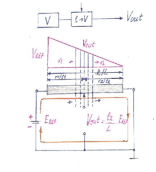
2. Moving the wiper of the rheostat (Vin1 = const, Vin2 = 0).
In this case we have a “moving-to-voltage” conversion. That means that while we move the wiper we change the output voltage.

3. Changing Vin1 (the rheostat resistance is constant, Vin2 = const).
In this case we have a “voltage-to-voltage” conversion. While we are changing the voltage Vin1, we are changing Vout. In other words, this is a “voltage-to-voltage” converter that is controlled from the left hand side.

4. Changing both Vin1 and Vin2.
In this case we have “invented” the voltage summer.

If these voltages have opposite polarities, our scheme becomes a comparing device. Somewhere on the rheostat we have a point with zero potential, that is named “virtual ground”.

Here, we have inserted some Wikipedia considerations about virtual ground point.
Virtual ground (or virtual earth) is a node of the circuit that is maintained at a steady reference potential, without being connected directly to the reference potential. In some cases the reference potential is considered to be the surface of the earth, and the reference node is called "ground" or "earth" as a consequence.
The virtual ground concept aids circuit analysis in operational amplifier and other circuits and provides useful practical circuit effects that would be difficult to achieve in other ways.
In circuit theory, a node may have any value of current or voltage but physical implementations of a virtual ground will have limitations of current handling ability and a non-zero impedance which may have practical side effects.
--Ludmila&Konstantin (talk) 12:15, 17 May 2008 (UTC)
Lab 2: Improving the genuine Ohm's experiment
[edit | edit source]Tuesday, March 18, 2008, 13.45 h
Ohm's law
[edit | edit source]1. Ohm's Law deals with the relationship between voltage and current in an ideal conductor. This relationship states that the potential difference (voltage) across an ideal conductor is proportional to the current through it. The constant of proportionality is called "resistance", R. Ohm's Law is given by: V = I.R where V is the potential difference between two points, which include a resistance R. I is the current flowing through the resistance. For biological work, it is often preferable to use the conductance, g = 1/R; in this form Ohm's Law is: I = g.V 2. Material that obeys Ohm's Law is called "ohmic" or "linear" because the potential difference across it varies linearly with the current.
3. Ohm's Law can be used to solve simple circuits. A complete circuit is one which is a closed loop. It contains at least one source of voltage (thus providing an increase of potential energy), and at least one potential drop i.e., a place where potential energy decreases. The sum of the voltages around a complete circuit is zero.
4. An increase of potential energy in a circuit causes a charge to move from a lower to a higher potential (i.e. voltage). Note the difference between potential energy and potential. Because of the electrostatic force, which tries to move a positive charge from a higher to a lower potential, there must be another 'force' to move charge from a lower potential to a higher inside the battery. This so-called force is called the electromotive force, or emf. The SI unit for the emf is a volt (and thus this is not really a force, despite its name). We will use a script E, the symbol, to represent the emf.
A decrease of potential energy can occur by various means. For example, heat lost in a circuit due to some electrical resistance could be one source of energy drop. Because energy is conserved, the potential difference across an emf must be equal to the potential difference across the rest of the circuit. That is, Ohm's Law will be satisfied: ε = I.R.
5. Here is a nice simulated experiment on Ohm's Law for you to test your understanding of this concept. Use the "back" button to return to this place. VanyaShiderova66b (talk)
Lab 3: Transistor circuits (trying to create a "diode" current mirror)
[edit | edit source]Tuesday, April 08, 2008, 13.45 h (extracted from the lab records made by a solid-state recorder) Circuit-fantasist 18:56, 29 May 2008 (UTC)
The idea of this lab is to transform the simplest transistor current source (that your colleagues from group 65b made an hour ago) into a current mirror circuit. You can see what they have discussed on the whiteboard and what they have made on the prototyping PCB. Well, let's first examine and discuss their creation and then try to metamorphose it to the desired circuit.
Look at the circuit on the whiteboard that is left from your colleagues. What do you see there? What is it? What is the idea of this circuit? What does the transistor do there? What is its behavior? What does the potentiometer do? What are these steady resistors? Why have they connected them in series with the varying ones? What does every component do in this circuit?
Well, let's begin reasoning to reveal the secret of this typical transistor circuit...
Understanding the transistor
[edit | edit source]We have to begin from somewhere; we need some idea to start the discussion... So, let's first consider the ubiquitous transistor. It is a three-terminal device... How have they connected it here? How do we connect three-terminal elements? They have connected one of its leads to the ground; so, the three-lead transistor is connected as a four-lead device. Also, in order to understand the more complex three-terminal transistor, we can break down it into simpler two-terminal parts. For example, we can first separate the output collector-emitter part as a two-terminal "element" and the input base-emitter part as another two-terminal "element"; then, to begin reasoning what does the transistor do.
Varying the input current
[edit | edit source]The simplest way to drive the transistor is by current. For this purpose, we have to connect only a base resistor Rb between the power supply and the transistor's base; for simplicity let's connect the same load resistor RL = Rb. Only, as a result, we get a current amplifier (Ic = βIb) instead the desired current mirror (Ic = Ib). How do we equalize the currents?
Varying the input voltage
[edit | edit source]We can connect a second resistor (actually, a potentiometer) in parallel to the base-emitter junction to divert the excessive current from the base to the ground. Where can we drive a transistor from? What is the input? The voltage between the base and the emitter drives the transistor. We can recognize in the left part of the circuit the ubiquitiuos potentiometer and a steady resistor connected in series. So, obviously the idea is to drive the transistor by a voltage. What is the mode of the transistor operation (saturated, active or cut off)? There are also measuring devices connected - two voltmeters and a (milli)ammeter.
What can we do with this circuit? We can vary its attributes one after another and observe its reaction to our intervention. Let's begin varying the input voltage. What happens, if we move the P's slider downwards to the end position? What is the input voltage then? Zero. Yes, there is no any input voltage. The output collector-emitter part of the transistor is in cut-off condition. The resistance between the collector and the emitter is infinite; no current flows in the output circuit. So, you can think of a transistor just as a varying resistor that has infinite resistance at these conditions (zero input voltage). Why the voltmeter V1 shows maximum voltage (equal to the supply voltage)? It is not so simple to explain why... Well, we have already discussed this phenomenon. We have a resistor whose upper end is connected to the positive rail of the power supply. What is the potential (the voltage regarding to the ground) of its lower end?
One possible viewpoint is to think of this circuit as a voltage divider with R1 = RL and R2 = ∞ (R2 >> R1; so, K ≈ 1. Another viewpoint is to see that the resistor R1 does not resist since there is nothing to resist (no current flows). Actually, there is no transistor connected in the circuit; we may erase it from the whiteboard...
The transistor is just a varying resistor
[edit | edit source]Now begin moving the potentiometer's slider up. At given moment the output voltage V2 begins lower; stop when it becomes somewhere between the supply rails (0 - 10 V), for instance in the middle (5 V). What is the mode of the transistor (saturated, active or cut off)? It is a "semi-opened"; so, it is in active mode. How does the transistor do this magic? Does it do something special? No, the transistor does not do anything supernatural in this region, it does the same what a tube, an FET, a rheostat, etc. would do, if they were at its place - it just changes its present resistance. So, the transistor is a varying resistor; only, it is an electrically controlled resistor. Well, if we have set a total load resistance RL = 10 kΩ and VCE = 5 V, what has the transistor done? It has set its present resistance RCE = 10 kΩ as well. It is just the same resistor as the collector one. Think of this circuit as a voltage divider with two identical resistors; its transfer ratio is K = 0.5.
This is the notion about a transistor that we need to understand how transistor circuits operate. All the active elements do the same; they are electrically controlled resistors. So, all the transistor circuits contain both ordinary resistors and electrically controlled resistors (active elements). They form the well-known voltage divider where transistors are put on the place of R1, R2 or the both.
If you continue moving up the slider, you will probably reach the saturation where V2 ∞ 0 V and the transistor is opened totally. What is the current now? It has a maximum value according to Ohm's law: I = VCC/RL.
Varying the load resistance
[edit | edit source]How have we arrived at a conclusion that the output part of the transistor behaves as a constant current source? We have somehow to check this speculation. For this purpose, we have to provoke the circuit and to see how it will react to our intervention. Well, what will we see if we vary the load resistance RL? The output transistor characteristic can give us the answer. Do you remember the subject of semiconductor devices? These characteristics are favorite topic for them. Only, they do not show how to use this transistor behavior. A student: the characteristic is horizontal; so, the current will not change, if the load varies. Yes, it is right. But what does the transistor do, what is its behavior to obtain such a characteristic?
Does the current change, if we vary the load resistance? A student: Yes, it does... But how do you explain it? Because the answer is exactly opposite - the current does not vary... Obviously, there are things that contradict our intuition and this is one of them... Well, look at the picture on the right (from Group 68b); it shows graphically how the transistor does this magic. Two IV characteristics are superimposed on a common coordinate system. The first curve is an IV characteristic of a real voltage source having a voltage VCC and an internal resistance RL (they name it "load line"). The slope of this curve depends on RL. If RL = 0, it is a vertical line; if RL > 0 it inclines proportionally to the resistance. The second curve represents the present output transistor resistance (RCE or shortly, RT).
The transistor does the following trick: if we try to decrease/increase the load resistance (to set upright the load line), it does the opposite - increases/decreases its present resistance (RCE or shortly, RT) so that the crossing (operating) point moves along the almost horizontal output characteristic of the transistor. As a result, the current stays almost constant. You can see how simple the idea of this dynamic constant current source is. It consists only of two elements: a voltage source and a dynamic resistor connected in series with the resistive load. The resistance of the dynamic resistor supplements the load resistance to a constant value (RL + RT = const); so, the current is constant - I = VCC/(RL + RT). Shortly, the dynamic resistor keeps up a constant total sum of the resistances.
A conclusion: If you connect in series a transistor and a resistor and begin varying the resistance of the resistor, the transistor will also begin changing its present resistance so that the sum of resistances to stay constant; as a result, the current stays constant. The transistor acts as a dynamic resistor that varies, as a current-stable resistor (an element that has the property to keep up a constant current).
And what about the voltage drop across the resistor? Does it vary? Move the slider and look at V2. If we lower RL, the voltage drop VL across the load lowers as well. But the transistor increases its present resistance RT and the voltage drop V2 across it increases as well. And vice versa; if we increase RL, the voltage drop VL across the load increases as well. Now, the transistor lowers its present resistance RT and the voltage drop V2 across it lowers as well.
A conclusion: If we vary the load resistance, the current stays constant but the voltages vary in wide limits.
However, at given moment the transistor depletes its reserve of resistance; it saturates and the voltage V2 across it becomes zero. The magic of dynamization ceases and if you continue changing the load resistance, the current will change according to Ohm's law.
Varying the supply voltage
[edit | edit source]Besides the load resistance, we can vary the supply voltage as well. Look at the picture on the whiteboard again and answer the question, "Will the current stay constant, if we vary the supply voltage VCC?" Well, try it on the lab set up. As we can see, the current varies. Why? What is the problem?
When we vary the supply voltage, the transistor would react to this new "intervention" as before: if we increase VCC, it would increase its present resistance RT and v.v. The transistor would keep up a constant ratio VCC/(RT + RL). But still the current varies... What is the reason? A student: The input voltage varies. Yes, this is the reason... The tragedy of this circuit is that they have supplied the input voltage divider by the same power supply. But we have not another power supply. What do we do then so that the current to stay constant when we vary the common supply voltage?
A student: ...to add another transistor... I don't know; tell where you will place this additional transistor. You have to have some idea to place it. What does a transistor stabilize? Do all colleagues understand that a transistor stabilizes current? A transistor is a current stabilizer while a diode is a voltage stabilizer. The characteristic of such a voltage-stable element is a vertical line. All the voltage-stable elements (diodes, zeners, LEDs, etc.) have such a characteristic; they behave as a voltage source.
A true diode sets the input current
[edit | edit source]

Another student:...to place a diode... Yes, this is the right answer, to place a diode but now you have to say where. Please, write it on the whiteboard; here are whiteboard markers. Do not are confused that it looks not so pretty because we "invent" the circuit scribbling on the whiteboard. The other alternative is to show "cut-and-dried" pretty circuits on slides or Powerpoint presentations...
Well, your colleague begins drawing a diode; is she drawing it in the right direction? By the way, I know there are diodes that are usually connected in a reverse direction. What are they? Students: ...zener diodes... Right but let's use an ordinary diode. Only, let's connect it correctly... Is the circuit written correctly?
Another student: Let's erase the potentiometer... Go and draw what you mean. Maybe, it is better not to remove the potentiometer; instead, draw it higher up and connect it properly, as a rheostat (do not forget to connect the slider). Leave it as an element that allows us to regulate the input current. It is time to make some shots. This room is not so suitable to make photos as a Hollywood studio but your colleagues do something great; so, they deserve to be perpetuated:)
Don't you think it's time to discover the web for similar solutions? For this purpose, write "current mirror" in the Google window. As usual, the corresponding Wikipedia page (too formal and boring) stays at the first position.
Let's then see Tony Kuphaldt's page about current mirrors. In the beginning, he is reasoning about Ebers-Moll diode equation. We can see the load and the transistor and now we exclaim with surprise - here is the same diode! Tony Kuphaldt has proposed what our colleagues has proposed as well - to improve the circuit by connecting a forward biased diode in parallel to the base-emitter junction. Then, the author begins telling what the profit is in connecting an ordinary diode.
Let's scrutinize the Tony Kuphaldt's circuit since I have the following idea. As he is a very good teacher and an excellent web writer, I intend to write an email to him where to describe our Wikibooks "open student project" and to invite him to join it. More concretely, I will tell him how you and I, all together, have arrived at his idea; then, how we have checked it and have found out that it is right (or not, now we have to decide). That is why it is so important to judge his circuit.
Tony claims that the output current flowing through the load is equal to the input current flowing through the diode: "Current through resistor Rload is therefore a function of current set by the bias resistor, the two being nearly equal." But is it true? Let's try it.
Who can solder? Choose a diode, solder it on the prototyping PCB and measure the currents. As I can remember, your colleague has told that a transistor consists of two diodes. Here we need a diode whose IV curve is identical to the IV curve of the transistor driving the load. What an idea can arise then? Imagine we have not an ordinary diode; we have only transistors...
A base-emitter transistor "diode" sets the input current
[edit | edit source]Replacing the true diode with a base-emitter transistor junction
[edit | edit source]Can we use the transistor as a diode? Yes, we can. In this case we can connect the base-emitter junction of an identical transistor (leaving the collector no connected) as a diode. A student: Yes, this was the lower circuit of Tony Kuphaldt...
They frequently use this "trick"... Even the transistor can be "semi-damaged"; we can use only one of its junctions (in this case we need exactly the base-emitter junction). Who will draw the new circuit? Let's the colleague to draw it. Leave the collector non-connected. Try to draw the circuit more symmetrically and turn it with the base to the other base; thus we will arrive easier to the great current mirror circuit. Finally, draw where currents flow by green current loops. All the currents begin from the positive lead of the supply voltage source and return to the negative one. First, an input current comes down from the positive rail, flows through the base resistor and arrived at the common point between the two bases. Here it strikes two p-n junctions connected in parallel (we have supposed they are identical). So, what will it do? The current will branch out into two directions - on the left and on the right; there are two base currents IB.
What is the idea of Tony Kuphaldt? It asserts that, if we create an input voltage by a stabilizer containing a resistor and a diode (or a base-emitter junction) acting as a voltage-stable element and apply this voltage to the base-emitter junction of another transistor, the two currents (the input and the output one) would be almost equal. Shortly, the two currents are equal since the two voltages are equal.
Then look for another but the same transistor and solder it. Who will show oneself? Only, let's connect another milliammeter in the input circuit. Can we expect that the two currents will be absolutely equal? No, we cannot since the two transistors are not absolutely identical; they are not selected. They made this structure exceptionally in integrated circuits. Who will solder? Look at the circuit on the whiteboard and implement it on the prototyping board. Do not remove the steady resistor connected in series to the potentiometer. Why is it there? It protects the base-emitter junctions of the transistors in a case when someone set zero resistance.
By the way, I have not ever carried out this experiment; so, I don't know what will happens. The result may be positive but maybe negative... And what do you think about the currents? Are they equal? Well, will check them later. Let's now tidy the measuring devices. Leave the voltmeter across the output transistor; we need it to know, if the transistor is in the active region. The two milliammeters will whow the two currents.
Now increase the input current by moving up the slider of the input rheostat. What about the output current? It does not "move"; it stays constant (about 2 mA). Why? Measure the input voltage (between the bases and emitters) to know why. As we can see, it is about 0.65 V. What does it mean? Maybe that the transistor is saturated... To make sure measure also the voltage VCE across the output resistor. You need a voltmeter; switch the ammeter as a voltmeter and connect it across the collector-emitter part of the second transistor. Only, close the loop by a piece of wire (use wires with alligators at the two ends)...
A problem appears: the transistor smokes!
[edit | edit source]Oh! The transistor begins smoking! It is warm! But why? What happens? It is impossible! If your circuit is the circuit that is drawn on the whiteboard, the transistor should not warm since there are "protecting" resistors of 3.9 kΩ connected in the base and in the collector circuits! There is another cause and you have to find it because it is very useful for us. IMO, there is some wrong connection... You can check the protecting resistors, if they are 3.9 kΩ. Yes, they are.
A student: I have found the cause - we have bypassed all the resistors connected in the collector! Maybe, the transistor is not damaged?
Well, let's check it. Alas! There is no voltage across the collector-emitter part; it seems the transistor is damaged. Or it is just saturated?
Only, our lab is finished. Your colleagues from the next Group 67b will continue your work.
(here, the record finishes) Circuit-fantasist 17:22, 2 June 2008 (UTC)
Lab 4: Op-amp inverting amplifier
[edit | edit source]Tuesday, April 22, 2008, 13.45 h
1.Principles of Negative Feedback (NFB)
The main idea of negative feedback is returning of the output (Y) back to the input (X) of the device (Image 1). In other words, we can think of this idea as a sort of active "tracing" or "following". Every device with negative feedback "solves" the equation X=Y. In order to do this, we need first energy (E). Also, we need a regulating element (R) to control the output quantity Y. The third element in our NFB device is a comparator (-), which will "analyse" the difference between X and Y and will give the result to the regulating element that have to reduce the difference to zero.
Devices and systems use NFB to compensate any disturbances that may occur during the working process.
Image 1:[1]
![[1]](http://i2.photobucket.com/albums/y12/yanita_bsb/NFB-shema.jpg)
2.Voltage Follower
This is the simplest operational amplifier configuration. It follows the voltage that is sent in. It is a very useful little circuit. You can use it to protect circuity of being overloaded. The voltage follower with an ideal op amp gives simply Vout = Vin. First, we have a Op-amp with NBF: Image 2:[2] Then we add 2 resistors: Image 3:[3] and now we have a Voltage Follower!!!
![[2]](http://i2.photobucket.com/albums/y12/yanita_bsb/vf_sch1.jpg)
![[3]](http://i2.photobucket.com/albums/y12/yanita_bsb/vf_sch2.jpg)
It's good to know that 2 resistors in series have the ability to subtrack 2 voltages: Image 4:[4]. An interesting fact is, that while trying to compensate the disturbances the follower is turning into an op-amp.
![[4]](http://i2.photobucket.com/albums/y12/yanita_bsb/schema.jpg)
Here we can see a resistive summer in ideal circuit:Image 5:[5]
![[5]](http://i2.photobucket.com/albums/y12/yanita_bsb/rezistivensumator-schema.jpg)
Yanita Petkova --shining*star (talk) 23:33, 17 May 2008 (UTC)