Blender 3D: Noob to Pro/Penguins from spheres
|
|
Applicable Blender version: 2.75. |
Note: Some Pictures are outdated.
Setup[edit | edit source]
Start with the default scene: it should contain a selected cube. Delete this cube by pressing X → Delete.

Put the 3D cursor at the scene center by pressing Shift + C .
- Note: after deleting the cube you must be in Object Mode. If not, Press CTRL-Z and switch with TAB and redo the operation.
Creating the body[edit | edit source]

Noob note: to ensure that you don't become confused, make sure that your viewport is set up in the same direction you see in these pictures. The colored arrows are red, green, and blue and they control the x, y, and z axes, respectively.)
- We start by creating our main body from a sphere. Press SHIFT + A → Mesh → UVSphere, then choose 16 segments and 16 rings.
We're going to make it look like a penguin body:
- Press TAB to enter Edit mode
- press NUM1 to switch to the front view,
- with all the vertices selected (if not, A ), choose the scale tool ( S ),
- restrict scaling to the Z-axis ( Z ),
- and move the mouse away from the 3D cursor while holding down the CTRL key (this snaps the scale values to whole numbers),
- Note: Make sure the mouse cursor is not too far away from the sphere when hitting the S or else you may not be able to reach a 2.000 scale value. The scaling steps are proportional to the distance from the 3D cursor when calling the scale tool.
- the current scale shows in the lower left corner of the viewport, click when you've reached 2.000 LMB ).
- Note: You can also do this by typing in 2 after starting the scale and restricting movement to the Z-axis: S -> Z -> 2
This is our main body!
Shaping the head[edit | edit source]
We’re going to shape the penguin head from the top of the sphere.

Start by selecting the top-most single vertex as well as the top two smallest circle segments.
- Note: Selection has been explained in a previous tutorial. Here, the easiest methods are either box selection B ) in the front view NUM1 ) and Limit selection to visible off, or lasso selection ( CTRL + LMB ) in the top view ( NUM7 ) and Limit selection to visible on. You can also switch to top view, center your mouse on the topmost vertex and use the circle tool. Don't forget to deselect all first ( A )
- Noob note: You can also select the top vertex and press CTRL + NUM+ twice to select the circle segments.
- Noob note: Make sure the Limit selection to visible/Occlude background geometry button is in the right state each time you select vertices, edges or faces. When it's off, selection affects any item, visible or not.
Building the neck with the 3D transform manipulators[edit | edit source]
To turn on the 3D transform manipulator, either push down its button ![]() or use CTRL + SPACE and choose Enable/Disable.
or use CTRL + SPACE and choose Enable/Disable.
Moving the two selected circles up[edit | edit source]

Go to the front view ( NUM1 ). Drag the blue arrow while holding the CTRL key down to move the selected vertices 0.3 units up.
- Noob note: you may not be able to snap the extrusion lengths to tenths of units. CTRL snaps to the grid size by default: if you can only translate by one unit (1.0), zoom in until the grid divides itself into tenths (SCROLL). Some Blender versions allow to snap to one tenth of the current step by holding both the SHIFT and CTRL keys while moving the mouse.
- Noob note: instead of the Transform manipulator, you can use the G and constraint the movement to the Z axis ( Z ).
Rotating the neck[edit | edit source]

Now switch to the side view ( NUM3 ) and make sure that the rotation/pivot point is set to "median point" either by selecting it from the third drop down menu right of the "Mesh" menu, or by pressing CTRL + , . Choose the Rotate tool ( R ). Move the mouse with the CTRL key down to rotate the selection 30 degrees counter-clockwise. Use LMB to validate the rotation.

Select an additional ring of vertices by expanding the selection ( CTRL + NUM+ (Note: NUM+ Refers to the addition symbol on the NUM Pad, KEY+ will not do.). You can contract the selection by pressing CTRL + NUM− . Move these vertices an additional 0.3 units up, then rotate them as previously 30 degrees counter-clockwise in the side view.

Repeat those steps (selection expansion, translation and rotation) two more times and you'll end up with the body seen in the below.
That doesn’t really look like a penguin, yet!

Now move all of the selected vertices to the left 0.4 units by pulling the manipulator's green arrow (and of course holding the CTRL key down). This straightens out the neck as seen in the next picture.
- Noob note: you can also use the G and translate the selection by -0.4 as displayed in the bottom left corner of the viewport. Still do this in the side view ( NUM3 ).
- Noob note if you had to pull the red arrow, not the green one, then you probably didn't switch to side view, and modeled the neck in front view. If you realize here that you have this done from another view then press AKEY twice, then NUM7, then Space -> Transform -> Rotate and type 90 or 270
Creating the beak[edit | edit source]

Switch to the front view ( NUM1 ), and select the frontmost vertex (the one that originally was the top vertex of the sphere) with the RMB . Then switch to the side view ( NUM3 ) and translate this vertex to the left by 1.2 units using the manipulator's green arrow or the translate tool.
- Note: some Blender versions allow moving the vertices from the keyboard with the following sequence: G , Y , -1.2, ENTER .
The main body of the penguin is now finished. The next step is to create some flappers for the poor little guy.
Extruding the wings[edit | edit source]
We are going to create the wings by extruding faces on each side of the penguin.
- Noob Note: You can rotate the whole object by pressing A to select all of its vertex and then rotate it pressing R or using the Rotate Manipulator until the axis on your screen matches the axis on the example image. That way, also, you can practice a little more.

Choose the side view ( NUM3 ) and switch to the Face select mode ( CTRL + TAB → Faces, or click on the orange-sided cube icon in the toolbar).

Now, select two faces that will make up the penguin’s shoulder as shown on the right (either select the first one with RMB and the second one holding SHIFT , or use box selection ( B ) to select them both in a single operation).

Then switch to front view ( NUM1 ) and extrude the selection:
- choose E → Region,
- constrain to the X axis ( X ),
- hold CTRL to snap,
- and move the mouse to extrude the shoulder by 0.2 to 0.3 units.

We'll now extrude the bottom face of this new extrusion. Rotate the view to show it with:
- a MMB drag,
- or several presses on NUM2 ,
- or CTRL + NUM7 (bottom view).
Press the A to deselect all, and select the bottom face ( RMB ), switch to front view ( NUM1 ), extrude by 1.4 units down ( E and CTRL ).
Now do the same on the penguin's other side: use CTRL + NUM3 to view the left side (you can also rotate with MMB , or press NUM4 several times).
Smoothing the wings[edit | edit source]
We’re going to smooth out the shoulders and improve the wings. Though this can be done in many ways, we'll only use the merge tool.

Rotate your penguin so that you can see one shoulder from above. Then switch to Vertex select mode ( CTRL + TAB → Vertices). Press A to deselect all, then select the two shoulder vertices with RMB and SHIFT .
Press ALT + M , choose At Center from the popup in order to merge the two vertices at their center. Finally dismiss the message saying Removed 1 Vertices.

Repeat the steps with the two other vertex pairs shown on the right picture, and smooth the other wing. I’m leaving the middle segments for now, else the wing tips will be too pointy.
- Note: if you have troubles merging vertices, it comes from vertex duplicates in your mesh. You probably chose Individual Faces instead of Region when extruding the wings, which creates duplicate vertices and neighbouring faces. To clean up your model: select all vertices ( A ) and choose W → Remove Doubles.
You must do them one by one!
Or, Alternatively, change into Edge select mode ( CTRL + TAB → Edge), select the edges to smooth ( CTRL + LMB ), press ALT + M , choose Collapse

Finish off the wings by selecting the two backmost vertices of the wings, and moving them up using the blue arrow by 0.1 unit.

You should now have something like this:
Cutting the underside[edit | edit source]


We're going to cut the penguin's lower end, for it to stand up! Select the bottom vertices (bottom vertex and the first ring above it) as shown in the picture. There are many ways, this is left as an exercise.
Once they're selected, delete them ( X → Vertices). Now our penguin is hollow: select all the vertices around the hole, and fill it using ALT + F .
- Noob note: To quickly select all the vertices around the hole, you can enter edge mode CTRL + TAB -> "Edges", and then select one edge that goes around the hole. Now press CTRL+E -> "Edge Loop Select", which should select all edges around the hole. Now go back to Vertex select mode and continue with ALT + F .
- Noob note: For Blender 2.56 In vertex select mode and occlude on hold down ALT and select one of the vertices all the vertices in the ring will be selected.
Adding the feet[edit | edit source]

The next step is to provide the little guy with feet. To do this, we’re going to extrude two of the front faces:
- choose the front view ( NUM1 ),
- switch to Face select mode,
- turn on Limit selection to visible,
- and select the face to the left and right of the middle two faces of the penguin.

Then switch to the side view ( NUM3 ) and extrude the selection by -0.6 units ( E → Region, restrict to the Y axis: Y ).

Keep the selection and look for the Mesh Tools in the Tool Shelf. If you can’t see it, press T to make the Tool Shelf visible. Then click on the Subdivide button (under Add in the Tools tab). Or press W and choose Subdivide.

Switch to "Vertex Select Mode", Now select the three middle vertices (or two edges) vertically at the tip of each foot, and drag them along the Y axis by 0.3 units towards the penguin
- Note: if something goes wrong here, you may need to remove double first. As always, to move the vertices, either use the manipulator or G and Y sequence.

You should end up with what's shown in the right picture (minus the selection).

The feet look too thick, let's flatten them a bit. Switch to the front view ( NUM1 ) and select the two bottom vertex rows (Limit selection to visible off, use either the lasso or box selection).

Then choose the scale tool ( S ), limit its action to the Z axis ( Z ) and scale down by a factor of 0.4.
The feet still look rather peculiar, so please go ahead and move the vertices around on your own as you like.
Reminder: you can use the G and restrict movements to the X or Y axis using the X or Y . Try not to move vertices along the Z axis to keep the penguin's bottom flat.
Extruding a tail[edit | edit source]


To complete the penguin, we have to add a tail (the end of the tuxedo):
- go to the back view ( CTRL + NUM1 ),
- make sure you're still in Vertex select mode,
- and that Limit selection to visible/Occlude background geometry is on.
Select the three middle vertices in the second row up from the bottom. Then, switch to the side view ( NUM3 ) and extrude the edges 0.3 units away from the penguin and 0.08 units down ( E → Edges), so that the end of the tail is at the same level as the bottom of the penguin.
Noob Note: Or you can extrude the edges 0.3 units away from the penguin, then G Z -0.08, LMB or ENTER .
Press CTRL + S to save your work!
Subsurfing[edit | edit source]

Go to Object Mode ( TAB ), and make sure the penguin is selected. Then check for the Modifiers toolkit in the Buttons panel. Press Add Modifier → Subsurf (or Press SHIFT + O ).
Look at the penguin now, he’s much smoother. You can alter the levels of the subsurfing if you like, but I’ll settle for level one. Under the Links and Materials toolkit, you can press the Set Smooth button as well, which makes the penguin really slick.
- Note: you may see some weird effects at the bottom and the tail after subsurfing the penguin. If so, there is an issue with normals: they have to be all pointing outwards. This can be achieved by selecting all vertices in Edit Mode and recalculating the normals outside ( CTRL + N ). Click on the message to confirm. Note that CTRL + SHIFT + N will turn the normals inwards and that W → Flip Normals flips them.
- Question: The finished penguin looks fine in Object Mode, but when I render it, it looks odd. Quite patchy.
- Answer: Make sure you adjust the "Render Levels" parameter (directly under "Levels") to be greater-or-equal than "Levels".
Extra[edit | edit source]
The penguin can be colored or textured, but that will be part of later tutorials!
-
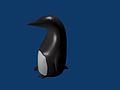
 This is what the penguin (sans tail) looks like, textured and ready. Orbisonitrum
 -
 The eyes are there, just not easily visible in the thumb. At the top of the white part, two faces on the chest were subdivided to give the white more of a curve at the top. The faces were selected that were going to be white, and the I used separate (P) to make them a different mesh. I used a white material for the chest, black for the body, and grey uvspheres for the eyes. Apparently, an easier way to colour the chest can be found at Multiple Materialsplease feel free to replace this with your own image of the penguin you made, with comments on how you put your own style into it
 -
 A pretty basic picture of a penguin. I subdivided the stomach and eyes, but then I also added some eyeballs by making a UVSphere, cutting the top of it off, and then placing it inside of my penguin's head. All the colors have specular colors, giving the penguin a slight blue glow under the black.


