Blender 3D: Noob to Pro/Modeling a Simple Person
|
|
Applicable Blender version: 2.57. |

In this module, you will model a simple human figure. Along the way, you will practice using extrusion and learn additional ways to select vertices, edges, and faces.
Start a New Scene
[edit | edit source]- Start with the default cube (File → Load Factory Settings) and NumLock "on".
- Press Tab to edit the cube.
- Scale the cube down 50% by pressing S . 5KEY ENTER .
Selection Methods
[edit | edit source]Just as you did for the house model, you will begin by selecting the top four vertices of the cube. This section presents six methods for doing so.
Ease of selection depends partly on the viewport settings and viewpoint. For greatest ease, you want a view in which the parts you are trying to select are both visible and close together.
For clarity, use a view of the cube in which all vertices are visible:
- Go to right side view with Num3 .
- Disable the manipulator widget with Ctrl + Space .
- Make sure the Limit selection to visible option is "off".

The picture on the right shows the cube with the correct vertices selected.
To begin, make sure you start in Vertex select mode.
Border Select Tool
[edit | edit source]The border select tool selects things that lie in a rectangular region of the viewport.
- Activate (place the mouse pointer in) a 3D View window.
- Deselect all vertices by pressing A .
- Press B to activate the border select tool. Two dashed gray lines should appear, one vertical and one horizontal, forming a crosshair in the viewpoint.
- Click and drag LMB diagonally across the area you want to select. The area will be outlined in dashed gray lines.
- When you release the mouse button, the vertices inside the rectangle will be added to the selection.
Practice selecting the top four vertices this way. If you make a mistake, press A and try again.
Circle Select Tool
[edit | edit source]The circle select tool selects or deselects things that lie in a circular region of the viewport.
- Activate a 3D View window.
- Deselect all vertices by pressing A .
- Press C to activate the circle select tool. A dashed gray circle should appear. note: Prior to Blender 2.5 B B twice.
When this tool is active, you can do various things:
- To move the select area, simply move the mouse pointer.
- To resize the select area, use SCROLL or Num+ / NUM− ..
- To select all vertices within the circle, click LMB .
- To deselect all vertices within the circle, click MMB or Shift + LMB .
- To deactivate the tool, press Esc or RMB .
Practice selecting the top four vertices this way. If you make a mistake, press A and try again.
Lasso Select Tool
[edit | edit source]Like many graphics programs, Blender 3D has a lasso select tool.
- Activate a 3D View window.
- Deselect all vertices by pressing A .
- Click and hold Ctrl + LMB .
- Drag the mouse pointer in a loop around the vertices you want to select. As you drag, a dashed gray line will appear.
- You can deselect with lasso by pressing Ctrl + Shift + LMB .
- Release the LMB when you're done.
Vertex by Vertex Selection
[edit | edit source]You can select (or deselect) vertices one by one, as you did in the "Quickie Model" module.
- Click RMB on a vertex to make it the only selected vertex.
- Toggle the select state of additional vertices by clicking Shift + RMB .
Edge Select Mode
[edit | edit source]You can select (or deselect) edges one by one, as you did in the "Improving Your House" module.
- Click LMB on the Edge select mode button in the 3D View header.
- Select the top left edge of the cube by clicking on it with RMB .
- Toggle the select state of top right edge of the cube by clicking on it with Shift + RMB .
- Switch back to Vertex select mode by clicking LMB on the Vertex select mode button in the 3D View header.
After you switch back to Vertex select mode, all four vertices in the two selected edges are selected.
Face Select Mode
[edit | edit source]You can select (or deselect) faces one by one, as you did in the "Improving Your House" module.
- Click LMB on the Face select mode button in the 3D View header.
- Select the top face of the cube by clicking on its center dot with RMB .
- Switch back to Vertex select mode by clicking LMB on the Vertex select mode button in the 3D View header.
After you switch back to Vertex select mode, all four vertices in selected face are selected.
Extruding Limbs
[edit | edit source]
The illustrations in this section are in front orthographic view, so:
- Use Num5 (or View → Orthographic) to switch to orthographic view.
- Use Num1 (or View → Front) to switch to front view.
Region Extrusion
[edit | edit source]- Make sure you're still in Edit Mode, with the top four vertices selected. (Only two will be visible in front ortho view.)
- Activate the extrude tool by using E (or Mesh → Extrude Region).
- Move the mouse pointer upwards. As you do, four new vertices will appear, each connected to one of the four that were previously selected.
The new vertices and their associated edges will move with the mouse pointer. You can lock them into place with LMB or Enter ).
Extruding a Leg
[edit | edit source]
Suppose you want to extrude a region the same size as the default cube -- in other words, one Blender unit on a side.
- Undo your previous extrude by pressing Ctrl + Z .
- Activate the extrude tool again by using E (or Mesh → Extrude Region).
- This time, as you're moving the extruded vertices around, hold down the Ctrl key. You'll see that the new vertices will only move in multiples of a Blender unit. This is called snapping, and it makes it easy to extrude by exactly one blender unit. The size of the snapping depends on the zoom level; if you are zoomed out a long way from the object the snapping will be done in large increments and if you are zoomed in close you can snap in finer amounts.
Continue extruding until you have five cubes of equal size stacked atop one another. This will be one leg of your figure.
|
Another way to extrude by exactly one Blender unit is to press 1key while the tool is active. If you press 2key when no tool is active, Blender will switch to the second layer, and your (first-layer) object will disappear. To make it visible again, press 1key . |
|
If you are not using Front Ortho view, the blender unit will be much larger than the cube. Switching to that view will allow for the proper size, although you can manually enter the extrusion as 0.4 units. |
|
Don't extrude any cube more than a unit at a time. You'll want those extra vertices, edges and faces later in this tutorial. |
|
If the mesh gets too big for your view, you can zoom out using SCROLL or NUM− |
Extruding the Pelvis
[edit | edit source]
- Press A until all vertices are deselected.
- Rotate the view (by dragging MMB ) so you can see all four vertices on the right face of the top cube.
- Select those four vertices.
- Extrude twice to the right.
Extruding the Rest of the Body
[edit | edit source]The same trick is repeated over and over to build the rest of our simple body.
|
To speed things up, you may want to switch to Face select mode. In Face select mode, you can select a face with a single click. |
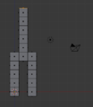
- Create a second leg by extruding down four times from the last cube of the pelvis.
- Create the torso by extruding up five times from the middle cube of the pelvis.
- Extrude to each side from the next-to-top cube of the torso to create arms. (Making sure there are five on each side. Refer to the picture on the top of the page)
-
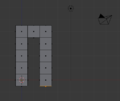 Legs and Pelvis
 -
 Torso
Torso -
 Arms
Arms


To be safe, remove any double vertices you may have inadvertently created:
- In Vertex select mode, press A until all vertices are selected.
- Make sure that you are in Edit Mode, Press RMB to bring up the Vertex Context Menu.
- Scroll over Merge Vertices, and then select By Distance.
Now check your work:
- Return to Object Mode by pressing Tab .
- Make sure the viewport draw type is Solid. (Press Z if it isn't.)
- Rotate the viewpoint and examine the body from every side (it might be useful to return to perspective view for this).
This is easily fixed. To create a face:
- Press Tab to go back into Edit Mode.
- Select four vertices.
- Press F (or choose Mesh → Faces → Make Edge/Face from the 3D View header).
- Note that you can also make edges with this tool if you select two vertices.
Adding the Head
[edit | edit source]
- Move the 3D cursor to a point above the neck by clicking with the LMB .
- Adjust the cursor position in orthographic top, front and side views ( Num7 , Num1 , and Num3 respectively) until the 3D cursor is about where the center of the head should be. It may help to use Shift + S → Snap → Cursor to Grid.
- Make sure you're in Edit Mode with a 3D View window active. (If you create the head in Object Mode, it will be a separate object from the body, and changes to the body later in this tutorial won't affect the head.)
- Create a sphere using Shift + A → Mesh → Icosphere.
- Leave the default settings for subdivisions and size in the bottom left of the screen. (Note: Your computer may slow down if you set subdivisions above 6)
You should now have a small sphere at the top of the body. To make it more proportional to the body, resize it using the scale tool:
- Make sure you're still in Edit Mode, with a 3D View window active and the head selected.
- If necessary change the pivot point to Median Point.
- Activate the scale tool by pressing S (or Mesh → Transform → Scale).
- Move the mouse pointer until the head is the size you want.
You may also adjust its position using the grab tool:
- Make sure you're still in Edit Mode, with a 3D View window active and the head selected.
- Activate the grab tool by pressing G (or Mesh → Transform → Grab/Move).
- Move the mouse pointer until the center of the head is where you want it.
|
If you deselect the head and then decide that you want to select it again:
|
Now check your work:

- Return to Object Mode by pressing Tab .
- Make sure the viewport draw type is Solid. (Press Z if it isn't.)
- Rotate the viewpoint and examine the body from every side. Make sure that the head connects properly to the neck.
Save Your Work
[edit | edit source]You will continue working on your simple person model in the next module.
To save the scene in a .blend file:
- Press ctrl + S (or select File → Save).
- Navigate to the directory (folder) where you want to write the file.
- Type a filename in the text box to the left of the "Cancel" button.
- Click LMB on the "Save Blender File" button.