Electronics Fundamentals/Passive Components/Capacitor
Electronics | Foreword | Basic Electronics | Complex Electronics | Electricity | Machines | History of Electronics | Appendix | edit

Capacitors are a good example of the fact that even the simplest device can become complicated given 250 years of evolution. (Citation J. Ho, T. R. Jow, St. Boggs, Historical Introduction to Capacitor Technology)[1]
Capacitors, together with resistors, inductors and memristors, belong to the group of "passive components" for electronic equipment. Although in absolute figures the most common capacitors are integrated capacitors, e.g. in DRAMs or in flash memory structures, this article is concentrated on discrete components.
Capacitors
[edit | edit source]Theory of conventional construction
[edit | edit source]
Model of a capacitor

A capacitor (historically known as a "condenser") is a device that stores energy in an electric field, by accumulating an internal imbalance of electric charge. It is made of two conductors separated by a dielectric (insulator). Using the same analogy of water flowing through a pipe, a capacitor can be thought of as a tank, in which the charge can be thought of as a volume of water in the tank. The tank can "charge" and "discharge" in the same manner as a capacitor does to an electric charge. A mechanical analogy is that of a spring. The spring holds a charge when it is pulled back.
When voltage exists one end of the capacitor is getting drained and the other end is getting filled with charge.This is known as charging. Charging creates a charge imbalance between the two plates and creates a reverse voltage that stops the capacitor from charging. As a result, when capacitors are first connected to voltage, charge flows only to stop as the capacitor becomes charged. When a capacitor is charged, current stops flowing and it becomes an open circuit. It is as if the capacitor gained infinite resistance.
You can also think of a capacitor as a fictional battery in series with a fictional resistance. Starting the charging procedure with the capacitor completely discharged, the applied voltage is not counteracted by the fictional battery, because the fictional battery still has zero voltage, and therefore the charging current is at its maximum. As the charging continues, the voltage of the fictional battery increases, and counteracts the applied voltage, so that the charging current decreases as the fictional battery's voltage increases. Finally the fictional battery's voltage equals the applied voltage, so that no current can flow into, nor out of, the capacitor.
Just as the capacitor charges it can be discharged. Think of the capacitor being a fictional battery that supplies at first a maximum current to the "load", but as the discharging continues the voltage of the fictional battery keeps decreasing, and therefore the discharge current also decreases. Finally the voltage of the fictional battery is zero, and therefore the discharge current also is then zero.
This is not the same as dielectric breakdown where the insulator between the capacitor plates breaks down and discharges the capacitor. That only happens at large voltages and the capacitor is usually destroyed in the process. A spectacular example of dielectric breakdown occurs when the two plates of the capacitor are brought into contact. This causes all the charge that has accumulated on both plates to be discharged at once. Such a system is popular for powering tasers which need lots of energy in a very brief period of time.
Theory of electrochemical construction
[edit | edit source]_NT.PNG)
1. IHP Inner Helmholtz Layer
2. OHP Outer Helmholtz Layer
3. Diffuse layer
4. Solvated ions
5. Specifically adsorptive ions (Pseudocapacitance)
6. Solvent molecule.
Besides the conventional static storage of electric energy in an electric field, two other storage principles to store electric energy in a capacitor exist. They are so-called electrochemical capacitors. In contrast to ceramic, film and electrolytic capacitors, supercapacitors, also known as electrical double-layer capacitors (EDLC) or ultracapacitors do not have a conventional dielectric. The capacitance value of an electrochemical capacitor is determined by two high-capacity storage principles. These principles are:
- electrostatic storage within Helmholtz double layers achieved on the phase interface between the surface of the electrodes and the electrolyte (double-layer capacitance) and the
- electrochemical storage achieved by a faradaic electron charge-transfer by specifically adsorpted ions with redox reactions (pseudocapacitance). Unlike batteries, in the faradaic redox reactions, the ions simply cling to the atomic structure of an electrode without making or braking chemical bonds, and no or negligibly small chemical modifications are involved in charge/discharge.
The ratio of the storage resulting from each principle can vary greatly, depending on electrode design and electrolyte composition. Pseudocapacitance can increase the capacitance value by as much as an order of magnitude over that of the double-layer by itself.[2]
Capacitor
[edit | edit source]Symbol
[edit | edit source]
Capacitance
[edit | edit source]The capacitance of a capacitor is a ratio of the amount of charge that will be present in the capacitor when a given potential (voltage) exists between its leads. The unit of capacitance is the farad which is equal to one coulomb per volt. This is a very large capacitance for most practical purposes; typical capacitors have values on the order of microfarads or smaller.

Where C is the capacitance in farads, V is the potential in volts, and Q is the charge measured in coulombs. Solving this equation for the potential gives:

Capacitor & Direct Current Voltage (DC)
[edit | edit source]- Charge Building
- When a Capacitor is connected with electricity source V. Charge will build up on each plates of capacitor of the same amount of charge but different in polarity . This process is called Capacitor Charging
- Storing Charge
- When both plates are charged up to voltage V then there is no difference in voltage between capacitor's plates and electricity source therefore no current flow in the circuit. This is called Storing Charge

- Charge discharge
- When the capacitor is connected to ground, current will flow from capacitor to ground until the voltage on capacitor's plates are equal to zero.
Therefore, a Capacitor is a device that can Build up Charge , Store Charge and Release Charge
Capacitor & Alternating Current Voltage (AC)
[edit | edit source]Voltage
[edit | edit source]
Current
[edit | edit source]
Reactance
[edit | edit source]Reactance is defined as the ratio of Voltage over Current

Impedance
[edit | edit source]Impedance is defined as the sum of Capacitor's Resistance and Reactance

Angle of Difference between Voltage and Current
[edit | edit source]For Lossless Capacitor
- Current will lead Voltage an angle 90 degree
For Lossy Capacitor
- Current will lead Voltage an angle θ degree where


Changing the value of R and C will change the value of Phase Angle, Angular Frequency, Frequency and Time
Capacitor Connection
[edit | edit source]Capacitors in Series
[edit | edit source]Capacitors in series are the same as increasing the distance between two capacitor plates. As well, it should be noted that placing two 100 V capacitors in series results in the same as having one capacitor with the total maximum voltage of 200 V. This, however, is not recommended to be done in practice, especially with capacitors of different values. In a capacitor network in series, all capacitors can have a different voltage over them.

In a series configuration, the capacitance of all the capacitors combined is the reciprocal of the sum of the reciprocals of the capacitance of all the capacitors.

Capacitors in Parallel
[edit | edit source]Capacitors in parallel are the same as increasing the total surface area of the capacitors to create a larger capacitor with more capacitance. In a capacitor network in parallel, all capacitors have the same voltage over them.

In a parallel configuration, the capacitance of the capacitors in parallel is the sum of the capacitance of all the capacitors.

RC Circuit
[edit | edit source]Introduction
[edit | edit source]An RC circuit is short for 'Resistor-Capacitor' circuit. A capacitor takes a finite amount of time to discharge through a resistor, which varies with the values of the resistor and capacitor. A capacitor acts interestingly in an electronic circuit, practically speaking as a combination of a voltage source and a variable resistor.
Basics
[edit | edit source]Below is a simple RC Circuit:

There is a capacitor in parallel with the resistor and current probe. The way the capacitor functions is by acting as a very low resistance load when the circuit is initially turned on. This is illustrated below:

Initially, the capacitor has a very low resistance, almost 0. Since electricity takes the path of least resistance, almost all the electricity flows through the capacitor, not the resistor, as the resistor has considerably higher resistance.

As a capacitor charges, its resistance increases as it gains more and more charge. As the resistance of the capacitor climbs, electricity begins to flow not only to the capacitor, but through the resistor as well:

Once the capacitor's voltage equals that of the battery, meaning it is fully charged, it will not allow any current to pass through it. As a capacitor charges its resistance increases and becomes effectively infinite (open connection) and all the electricity flows through the resistor.

Once the voltage source is disconnected, however, the capacitor acts as a voltage source itself:

As time goes on, the capacitor's charge begins to drop, and so does its voltage. This means less current flowing through the resistor:
Once the capacitor is fully discharged, you are back to square one:
If one were to do this with a light and a capacitor connected to a battery, what you would see is the following:
- Switch is closed. Light does not light up.
- Light gradually becomes brighter and brighter...
- Light is at full luminosity.
- Switch is released. Light continues to shine.
- Light begins to fade...
- Light is off.
This is how a capacitor acts. However, what if you changed the values of R1? C1? The voltage of the battery? We will examine the mathematical relationship between the resistor, capacitor, and charging rate below.
Time Constant
[edit | edit source]In order to find out how long it takes for a capacitor to fully charge or discharge, or how long it takes for the capacitor to reach a certain voltage, you must know a few things. First, you must know the starting and finishing voltages. Secondly, you must know the time constant of the circuit you have. Time constant is denoted by the Greek letter 'tau' or τ. The formula to calculate this time constant is:

So this means that the time constant is how long it takes for a capacitor to charge to 63% of its full charge. This time, in seconds, is found by multiplying the resistance in ohms and the capacitance in farads.
According to the formula above, there are two ways to lengthen the amount of time it takes to discharge. One would be to increase the resistance, and the other would be to increase the capacitance of the capacitor. This should make sense. It should be noted that the formula compounds, such that in the second time constant, it charges another 63%, based on the original 63%. This gives you about 86.5% charge in the second time constant. Below is a table.
| Time Constant | Charge |
|---|---|
| 1 | 63% |
| 2 | 87% |
| 3 | 95% |
| 4 | 98% |
| 5 | 99+% |
For all practicality, by the 5th time constant it is considered that the capacitor is fully charged or discharged.
put some stuff in here about how discharging works the same way, and the function for voltage based on time

Where i(t) is the current flowing through the capacitor as a function of time.
This equation is often used in another form. By differentiating with respect to time:

Substituting v/r for i(t) and integrating the above equation gives you an equation used to describe the charging and discharging characteristics of RC circuits. A charging characteristic curve exponentially increases from 0% (0 volts) and approaches 100% full (maximum voltage), similarly, a discharge curve starts at the theoretical 100% (maximum voltage) and exponentially falls back to 0% (0 volts).
Capacitors - general remarks
[edit | edit source]Common capacitors and their names
[edit | edit source]Capacitors are divided into two mechanical groups: Fixed capacitors with fixed capacitance values and variable capacitors with variable (trimmer) or adjustable (tunable) capacitance values.
The most important group is the fixed capacitors. Many got their names from the dielectric. For a systematic classification these characteristics can't be used, because one of the oldest, the electrolytic capacitor, is named instead by its cathode construction. So the most-used names are simply historical.
The most common kinds of capacitors are:
- Ceramic capacitors have a ceramic dialectric.
- Film and paper capacitors are named for their dielectrics.
- Aluminum, tantalum and niobium electrolytic capacitors are named after the material used as the anode and the construction of the cathode
- Supercapacitor is the family name for:
- Double-layer capacitors were named for the physical phenomenon of the Helmholtz double-layer
- Pseudocapacitors were named for their ability to store electric energy electro-chemically with reversible faradaic charge-transfer
- Hybrid capacitors combine double-layer and pseudocapacitors to increase power density
- Seldom-used Silver mica, glass, silicon, air-gap and vacuum capacitors were named for their dielectric.
Capacitors in each family have similar physical design features, but vary, for example, in the form of the terminals.

In addition to the above shown capacitor types, which derived their name from historical development, there are many individual capacitors that have been named based on their application. They include:
- Power capacitors, motor capacitors, DC-link capacitors, suppression capacitors, audio crossover capacitors, lighting ballast capacitors, snubber capacitors, coupling, decoupling or bypassing capacitors.
Often, more than one capacitor family is employed for these applications, e.g. interference suppression can use ceramic capacitors or film capacitors.
Specialized devices such as built-in capacitors with metal conductive areas in different layers of a multi-layer printed circuit board and kludges such as twisting together two pieces of insulated wire also exist.
Dielectrics
[edit | edit source]
The most common dielectrics are:
- Ceramics
- Plastic films
- Oxide layer on metal (Aluminum, Tantalum, Niobium)
- Natural materials like mica, glass, paper, air, vacuum
All of them store their electrical charge statically within an electric field between two (parallel) electrodes.
Beneath this conventional capacitors a family of electrochemical capacitors called Supercapacitors was developed. Supercapacitors don't have a conventional dielectric. They store their electrical charge statically in
- Helmholtz double-layers (Double-layer capacitors)
and additional electrochemical with faradaic charge transfer
- with a pseudocapacitance (Pseudocapacitors)
- or with both storage principles together (Hybrid capacitors).
The most important material parameters of the different dielectrics used and the appr. Helmholtz-layer thickness are given in the table below.
| Capacitor style | Dielectric | Permittivity at 1 kHz |
Maximum/realized. dielectric strength V/µm |
Minimum thickness of the dielectric µm |
|---|---|---|---|---|
| Ceramic capacitors, Class 1 |
paraelectric | 12–40 | < 100(?) | 1 |
| Ceramic capacitors, Class 2 |
ferroelectric | 200–14,000 | < 25(?) | 0.5 |
| Film capacitors | Polypropylene ( PP) | 2.2 | 650/450 | 1.9 – 3.0 |
| Film capacitors | Polyethylen terephthalate, Polyester (PET) |
3.3 | 580/280 | 0.7–0.9 |
| Film capacitors | Polyphenylene sulfide (PPS) | 3.0 | 470/220 | 1.2 |
| Film capacitors | Polyethylene naphthalate (PEN) | 3.0 | 500/300 | 0.9–1.4 |
| Film capacitors | Polytetrafluoroethylene (PTFE) | 2.0 | 450(?)/250 | 5.5 |
| Paper capacitors | Paper | 3.5–5.5 | 60 | 5–10 |
| Aluminium electrolytic capacitors | Aluminium oxide Al2O3 |
9,6[8] | 710 | < 0.01 (6.3 V) < 0.8 (450 V) |
| Tantalum electrolytic capacitors | Tantalum pentoxide Ta2O5 |
26[8] | 625 | < 0.01 (6.3 V) < 0.08 (40 V) |
| Niobium electrolytic capacitors | Niobium pentoxide, Nb2O5 |
42 | 455 | < 0.01 (6.3 V) < 0.10 (40 V) |
| Supercapacitors Double-layer capacitors |
Helmholtz double-layer | - | - | < 0.001 (2.7 V) |
| Vacuum capacitors | Vacuum | 1 | 40 | - |
| Air gap capacitors | Air | 1 | 3.3 | - |
| Glass capacitors | Glass | 5–10 | 450 | - |
| Mica capacitors | Mica | 5–8 | 118 | 4–50 |
The capacitor's plate area can be adapted to the wanted capacitance value. The permittivity and the dielectric thickness are the determining parameter for capacitors. Ease of processing is also crucial. Thin, mechanically flexible sheets can be wrapped or stacked easily, yielding large designs with high capacitance values. Razor-thin metallized sintered ceramic layers covered with metallized electrodes however, offer the best conditions for the miniaturization of circuits with SMD styles.
A short view to the figures in the table above gives the explanation for some simple facts:
- Supercapacitors have the highest capacitance density because of its special charge storage principles
- Electrolytic capacitors have lesser capacitance density than supercapacitors but the highest capacitance density of conventional capacitors because its thin dielectric.
- Ceramic capacitors class 2 have much higher capacitance values in a given case than class 1 capacitors because of their much higher permittivity.
- Film capacitors with their different plastic film material do have a small spread in the dimensions for a given capacitance/voltage value of a film capacitor because the minimum dielectric film thickness differs between the different film materials.
Capacitance and voltage range
[edit | edit source]
Capacitance ranges from picofarad to more than hundreds of farad. Voltage ratings can reach 100 kilovolts. In general, capacitance and voltage correlates with physical size and cost.
Miniaturization
[edit | edit source]
As in other areas of electronics, volumetric efficiency measures the performance of electronic function per unit volume. For capacitors, the volumetric efficiency is measured with the "CV product", calculated by multiplying the capacitance (C) by the maximum voltage rating (V), divided by the volume. From 1970 to 2005, volumetric efficiencies have improved dramatically.
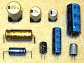
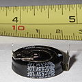
- Miniaturizing of capacitors
-
 Stacked paper capacitor (Block capacitor) from 1923 for noise decoupling (blocking) in telegraph lines
 -
 Wound metallized paper capacitor from the early 1930s in hardpaper case, capacitance value specified in "cm" in the cgs system; 5,000 cm corresponds to 28 nF
 -
 Folded wet aluminum electrolytic capacitor, Bell System 1929, view onto the folded anode, which was mounted in a squared housing (not shown) filled with liquid electrolyte
 -
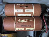 Two 8 μF, 525 V wound wet aluminum electrolytic capacitors in paper housing sealed with tar out of a 1930s radio.


Overlapping range of applications
[edit | edit source]These individual capacitors can perform their application independent of their affiliation to an above shown capacitor type, so that an overlapping range of applications between the different capacitor types exists.

Capacitor - types and styles
[edit | edit source]Ceramic capacitors
[edit | edit source]
A ceramic capacitor is a non-polarized fixed capacitor made out of two or more alternating layers of ceramic and metal in which the ceramic material acts as the dielectric and the metal acts as the electrodes. The ceramic material is a mixture of finely ground granules of paraelectric or ferroelectric materials, modified by mixed oxides that are necessary to achieve the capacitor's desired characteristics. The electrical behavior of the ceramic material is divided into two stability classes:
- Class 1 ceramic capacitors with high stability and low losses compensating the influence of temperature in resonant circuit application. Common EIA/IEC code abbreviations are C0G/NP0, P2G/N150, R2G/N220, U2J/N750 etc.
- Class 2 ceramic capacitors with high volumetric efficiency for buffer, by-pass and coupling applications Common EIA/IEC code abbreviations are: X7R/2XI, Z5U/E26, Y5V/2F4, X7S/2C1, etc.
The great plasticity of ceramic raw material works well for many special applications and enables an enormous diversity of styles, shapes and great dimensional spread of ceramic capacitors. The smallest discrete capacitor, for instance, is a "01005" chip capacitor with the dimension of only 0.4 mm × 0.2 mm.
The construction of ceramic multilayer capacitors with mostly alternating layers results in single capacitors connected in parallel. This configuration increases capacitance and decreases all losses and parasitic inductances. Ceramic capacitors are well-suited for high frequencies and high current pulse loads.
Because the thickness of the ceramic dielectric layer can be easily controlled and produced by the desired application voltage, ceramic capacitors are available with rated voltages up to the 30 kV range.
Some ceramic capacitors of special shapes and styles are used as capacitors for special applications, including RFI/EMI suppression capacitors for connection to supply mains, also known as safety capacitors,[9][10] X2Y® capacitors for bypassing and decoupling applications,[11] feed-through capacitors for noise suppression by low-pass filters[12] and ceramic power capacitors for transmitters and HF applications.[13][14]
- Diverse styles of ceramic capacitors
-
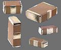
 Multi-layer ceramic capacitors (MLCC chips) for SMD mounting
 -
 Ceramic X2Y® decoupling capacitors
 -
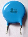 Ceramic EMI suppression capacitors for connection to the supply mains (safety capacitor)
 -
 High voltage ceramic power capacitor


| Capacitor type | Dielectric | Features/applications | Disadvantages |
|---|---|---|---|
| Ceramic Class 1 capacitors | paraelectric ceramic mixture of Titanium dioxide modified by additives | Predictable linear and low capacitance change with operating temperature. Excellent high frequency characteristics with low losses. For temperature compensation in resonant circuit application. Available in voltages up to 15,000 V | Low permittivity ceramic, capacitors with low volumetric efficiency, larger dimensions than Class 2 capacitors |
| Ceramic Class 2 capacitors | ferroelectric ceramic mixture of barium titanate and suitable additives | High permittivity, high volumetric efficiency, smaller dimensions than Class 1 capacitors. For buffer, by-pass and coupling applications. Available in voltages up to 50,000 V. | Lower stability and higher losses than Class 1. Capacitance changes with change in applied voltage, with frequency and with aging effects. Slightly microphonic |
Film capacitors
[edit | edit source]
Film capacitors or plastic film capacitors are non-polarized capacitors with an insulating plastic film as the dielectric. The dielectric films are drawn to a thin layer, provided with metallic electrodes and wound into a cylindrical winding. The electrodes of film capacitors may be metallized aluminum or zinc, applied on one or both sides of the plastic film, resulting in metallized film capacitors or a separate metallic foil overlying the film, called film/foil capacitors.
Metallized film capacitors offer self-healing properties. Dielectric breakdowns or shorts between the electrodes do not destroy the component. The metallized construction makes it possible to produce wound capacitors with larger capacitance values (up to 100 µF and larger) in smaller cases than within film/foil construction.
Film/foil capacitors or metal foil capacitors use two plastic films as the dielectric. Each film is covered with a thin metal foil, mostly aluminium, to form the electrodes. The advantage of this construction is the ease of connecting the metal foil electrodes, along with an excellent current pulse strength.
A key advantage of every film capacitor's internal construction is direct contact to the electrodes on both ends of the winding. This contact keeps all current paths very short. The design behaves like a large number of individual capacitors connected in parallel, thus reducing the internal ohmic losses (ESR) and parasitic inductance (ESL). The inherent geometry of film capacitor structure results in low ohmic losses and a low parasitic inductance, which makes them suitable for applications with high surge currents (snubbers) and for AC power applications, or for applications at higher frequencies.
The plastic films used as the dielectric for film capacitors are Polypropylene (PP), Polyester (PET), Polyphenylene sulfide (PPS), Polyethylene naphthalate (PEN), and Polytetrafluoroethylene or Teflon (PTFE). Polypropylene film material with a market share of something about 50% and Polyester film with something about 40% are the most used film materials. The rest of something about 10% will be used by all other materials including PPS and paper with roughly 3%, each.[15][16]
| Film material, abbreviated codes | |||||
|---|---|---|---|---|---|
| Film characteristics | PET | PEN | PPS | PP | |
| Relative permittivity at 1 kHz | 3.3 | 3.0 | 3.0 | 2.2 | |
| Minimum film thickness (µm) | 0.7–0.9 | 0.9–1.4 | 1.2 | 2.4–3.0 | |
| Moisture absorption (%) | low | 0.4 | 0.05 | <0.1 | |
| Dielectric strength (V/µm) | 580 | 500 | 470 | 650 | |
| Commercial realized voltage proof (V/µm) |
280 | 300 | 220 | 400 | |
| DC voltage range (V) | 50–1,000 | 16–250 | 16–100 | 40–2,000 | |
| Capacitance range | 100 pF–22 µF | 100 pF–1 µF | 100 pF–0.47 µF | 100 pF–10 µF | |
| Application temperature range (°C) | −55 to +125 /+150 | −55 to +150 | −55 to +150 | −55 to +105 | |
| ΔC/C versus temperature range (%) | ±5 | ±5 | ±1.5 | ±2.5 | |
| Dissipation factor (•10−4) | |||||
| at 1 kHz | 50–200 | 42–80 | 2–15 | 0.5–5 | |
| at 10 kHz | 110–150 | 54–150 | 2.5–25 | 2–8 | |
| at 100 kHz | 170–300 | 120–300 | 12–60 | 2–25 | |
| at 1 MHz | 200–350 | – | 18–70 | 4–40 | |
| Time constant RInsul•C (s) | at 25 °C | ≥10,000 | ≥10,000 | ≥10,000 | ≥100,000 |
| at 85 °C | 1,000 | 1,000 | 1,000 | 10,000 | |
| Dielectric absorption (%) | 0.2–0.5 | 1–1.2 | 0.05–0.1 | 0.01–0.1 | |
| Specific capacitance (nF•V/mm3) | 400 | 250 | 140 | 50 | |
Some film capacitors of special shapes and styles are used as capacitors for special applications, including RFI/EMI suppression capacitors for connection to the supply mains, also known as safety capacitors,[17] Snubber capacitors for very high surge currents,[18] Motor run capacitors, AC capacitors for motor-run applications[19]
- High pulse current load is the most important feature of film capacitors so many of the available styles do have special terminations for high currents
-
 Radial style (single ended) for through-hole solder mounting on printed circuit boards
 -
 SMD style for printed circuit board surface mounting, with metallized contacts on two opposite edges
 -
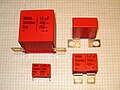 Radial style with heavy-duty solder terminals for snubber applications and high surge pulse loads
 -
 Heavy-duty snubber capacitor with screw terminals


| Capacitor type | Dielectric | Features/applications | Disadvantages |
|---|---|---|---|
| Metallized film capacitors | PP, PET, PEN, PPS, (PTFE) | Metallized film capacitors are significantly smaller in size than film/foil versions and have self-healing properties. | Thin metallized electrodes limit the maximum current carrying capability respectively the maximum possible pulse voltage. |
| Film/foil film capacitors | PP, PET, PTFE | Film/foil film capacitors have the highest surge ratings/pulse voltage, respectively. Peak currents are higher than for metallized types. | No self-healing properties: internal short may be disabling. Larger dimensions than metallized alternative. |
| Polypropylene (PP) film capacitors | Polypropylene (Treofan®) |
Most popular film capacitor dielectric. Predictable linear and low capacitance change with operating temperature. Suitable for applications in Class-1 frequency-determining circuits and precision analog applications. Very narrow capacitances. Extremely low dissipation factor. Low moisture absorption, therefore suitable for "naked" designs with no coating. High insulation resistance. Usable in high power applications such as snubber or IGBT. Used also in AC power applications, such as in motors or power factor correction. Very low dielectric losses. High frequency and high power applications such as induction heating. Widely used for safety/EMI suppression, including connection to power supply mains. | Maximum operating temperature of 105 °C. Relatively low permittivity of 2.2. PP film capacitors tend to be larger than other film capacitors. More susceptible to damage from transient over-voltages or voltage reversals than oil-impregnated MKV-capacitors for pulsed power applications. |
| Polyester (PET) film (Mylar) capacitors |
Polyethylene terephthalate, Polyester (Hostaphan®, Mylar®) | Smaller in size than functionally comparable polypropylene film capacitors. Low moisture absorption. Have almost completely replaced metallized paper and polystyrene film for most DC applications. Mainly used for general purpose applications or semi-critical circuits with operating temperatures up to 125 °C. Operating voltages up to 60,000 V DC. | Usable at low (AC power) frequencies. Limited use in power electronics due to higher losses with increasing temperature and frequency. |
| Polyethylene naphthalate (PEN) film capacitors |
Polyethylene naphthalate (Kaladex®) | Better stability at high temperatures than PET. More suitable for high temperature applications and for SMD packaging. Mainly used for non-critical filtering, coupling and decoupling, because temperature dependencies are not significant. | Lower relative permittivity and lower dielectric strength imply larger dimensions for a given capacitance and rated voltage than PET. |
| Polyphenylene Sulfide (PPS) film capacitors |
Polyphenylene (Torelina®) | Small temperature dependence over the entire temperature range and a narrow frequency dependence in a wide frequency range. Dissipation factor is quite small and stable. Operating emperatures up to 270 °C. Suitable for SMD. Tolerate increased reflow soldering temperatures for lead-free soldering mandated by the RoHS 2002/95/European Union directive | Above 100 °C, the dissipation factor increases, increasing component temperature, but can operate without degradation. Cost is usually higher than PP. |
| Polytetrafluoroethylene (PTFE) (Teflon film) capacitors |
Polytetrafluoroethylene (Teflon®) | Lowest loss solid dielectric. Operating temperatures up to 250 °C. Extremely high insulation resistance. Good stability. Used in mission-critical applications. | Large size (due to low dielectric constant). Higher cost than other film capacitors. |
| Polycarbonate (PC) film capacitors |
Polycarbonate | Almost completely replaced by PP | Limited manufacturers |
| Polystyrene (PS) film capacitors |
Polystyrene (Styroflex) | Almost completely replaced by PET | Limited manufacturers |
| Polysulphone film capacitors | Polysulfone | Similar to polycarbonate. Withstand full voltage at comparatively higher temperatures. | Only development, no series found (2012) |
| Polyamide film capacitors | Polyamide | Operating temperatures of up to 200 °C. High insulation resistance. Good stability. Low dissipation factor. | Only development, no series found (2012) |
| Polyimide film (Kapton) capacitors |
Polyimide (Kapton) | Highest dielectric strength of any known plastic film dielectric. | Only development, no series found (2012) |
Film power capacitors
[edit | edit source]
A related type is the power film capacitor. The materials and construction techniques used for large power film capacitors mostly are similar to those of ordinary film capacitors. However, capacitors with high to very high power ratings for applications in power systems and electrical installations are often classified separately, for historical reasons. The standardization of ordinary film capacitors is oriented on electrical and mechanical parameters. The standardization of power capacitors by contrast emphasizes the safety of personnel and equipment, as given by the local regulating authority.
As modern electronic equipment gained the capacity to handle power levels that were previously the exclusive domain of "electrical power" components, the distinction between the "electronic" and "electrical" power ratings blurred. Historically, the boundary between these two families was approximately at a reactive power of 200 volt-amps.
Film power capacitors mostly use polypropylene film as the dielectric. Other types include metallized paper capacitors (MP capacitors) and mixed dielectric film capacitors with polypropylene dielectrics. MP capacitors serve for cost applications and as field-free carrier electrodes (soggy foil capacitors) for high AC or high current pulse loads. Windings can be filled with an insulating oil or with epoxy resin to reduce air bubbles, thereby preventing short circuits.
They find use as converters to change voltage, current or frequency, to store or deliver abruptly electric energy or to improve the power factor. The rated voltage range of these capacitors is from approximately120 V AC (capacitive lighting ballasts) to 100 kV.[20]
- Power film capacitors for applications in power systems, electrical installations and plants
-
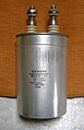 Power film capacitor for AC Power factor correction (PFC), packaged in a cylindrical metal can
 -
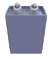 Power film capacitor in rectangular housing
 -
-
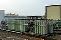
 75MVAR substation capacitor bank at 150kV


| Capacitor type | Dielectric | Features/applications | Disadvantages |
|---|---|---|---|
| Metallized paper power capacitors | Paper impregnated with insulating oil or epoxy resin | Self-healing properties. Originally impregnated with wax, oil or epoxy. Oil-Kraft paper version used in certain high voltage applications. Mostly replaced by PP. | Large size. Highly hygroscopic, absorbing moisture from the atmosphere despite plastic enclosures and impregnates. Moisture increases dielectric losses and decreases insulation resistance. |
| Paper film/foil power capacitors | Kraft paper impregnated with oil | Paper covered with metal foils as electrodes. Low cost. Intermittent duty, high discharge applications. | Physically large and heavy. Significantly lower energy density than PP dielectric. Not self-healing. Potential catastrophic failure due to high stored energy. |
| PP dielectric, field-free paper power capacitors (MKV power capacitors) |
Double-sided (field-free) metallized paper as electrode carrier. PP as dielectic, impregnated with insulating oil, epoxy resin or insulating gas | Self-healing. Very low losses. High insulation resistance. High inrush current strength. High thermal stability. Heavy duty applications such as commutating with high reactive power, high frequencies and a high peak current load and other AC applications. | Physically larger than PP power capacitors. |
| Single- or double-sided metallized PP power capacitors |
PP as dielectric, impregnated with insulating oil, epoxy resin or insulating gas | Highest capacitance per volume power capacitor. Self-healing. Broad range of applications such as general-purpose, AC capacitors, motor capacitors, smoothing or filtering, DC links, snubbing or clamping, damping AC, series resonant DC circuits, DC discharge, AC commutation, AC power factor correction. | critical for reliable high voltage operation and very high inrush current loads, limited heat resistance (105 °C) |
| PP film/foil power capacitors | Impregnated PP or insulating gas, insulating oil, epoxy resin or insulating gas | Highest inrush current strength | Larger than the PP metallized versions. Not self-healing. |
Electrolytic capacitors
[edit | edit source]Electrolytic capacitors have a metallic anode covered with an oxidized layer used as dielectric. The second electrode is a non-solid (wet) or solid electrolyte. Electrolytic capacitors are polarized. Three families are available, categorized according to their dielectric.
- Aluminum electrolytic capacitors with aluminum oxide as dielectric
- Tantalum electrolytic capacitors with tantalum pentoxide as dielectric
- Niobium electrolytic capacitors with niobium pentoxide as dielectric.
The anode is highly roughened to increase the surface area. This and the relatively high permittivity of the oxide layer gives these capacitors very high capacitance per unit volume compared with film- or ceramic capacitors.
The permittivity of tantalum pentoxide is approximately three times higher than aluminium dioxide, producing significantly smaller components. However, permittivity determines only the dimensions. Electrical parameters, especially conductivity, are established by the electrolyte's material and composition. Three general types of electrolytes are used:
- non solid (wet, liquid)—conductivity approximately 10 mS/cm and are the lowest cost
- solid manganese oxide—conductivity approximately 100 mS/cm offer high quality and stability
- solid conductive polymer (Polypyrrole)—conductivity approximately 10,000 mS/cm,[21] offer ESR values as low as <10 mΩ
Internal losses of electrolytic capacitors, prevailing used for decoupling and buffering applications, are determined by the kind of electrolyte.
| Anode material | Electrolyte | Capacitance range (µF) |
Max. rated voltage at 85 °C (V) |
Upper categorie temperature (°C) |
Specific ripple current (mA/mm3) 1) |
|---|---|---|---|---|---|
| Aluminum (roughned foil) |
non solid, e.g. Ethylene glycol, DMF, DMA, GBL |
0.1–2,700,000 | 600 | 150 | 0.05–2.0 |
| solid, Manganese dioxide (MnO2 |
0.1–1,500 | 40 | 175 | 0.5–2.5 | |
| solid conductive polymere (e.g. Polypyrrole) |
10–1,500 | 25 | 125 | 10–30 | |
| Tantalum (roughned foil) |
non solid Sulfuric acid |
0.1–1,000 | 630 | 125 | – |
| Tantalum (sintered) |
non solid sulfuric acid |
0.1–15,000 | 150 | 200 | – |
| solid Manganese dioxide (MnO2 |
0.1–3,300 | 125 | 150 | 1.5–15 | |
| solid conductive polymere (e.g. Polypyrrole) |
10–1,500 | 35 | 125 | 10–30 | |
| Niobium (sintered) |
solid Manganese dioxide (MnO2 |
1–1,500 | 10 | 125 | 5–20 |
| solid conductive polymere (e.g. Polypyrrole) |
2.2–1,000 | 25 | 105 | 10–30 | |
| |||||
The large capacitance per unit volume of electrolytic capacitors make them valuable in relatively high-current and low-frequency electrical circuits, e.g. in power supply filters for decoupling unwanted AC components from DC power connections or as coupling capacitors in audio amplifiers, for passing or bypassing low-frequency signals and storing large amounts of energy. The relatively high capacitance value of an electrolytic capacitor combined with the very low ESR of the polymer electrolyte of polymer capacitors, especially in SMD styles, makes them a competitor to MLC chip capacitors in personal computer power supplies.
Bipolar electrolytics (also called Non-Polarized capacitors) contain two anodized aluminium foils, behaving like two capacitors connected in series opposition.
Electolytic capacitors for special applications include motor start capacitors,[22] flashlight capacitors[23] and audio frequency capacitors.[24]
- Schematic representation
-
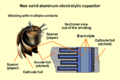 Schematic representation of the structure of a wound aluminum electrolytic capacitor with non solid (liquid) electrolyte
 -
 Schematic representation of the structure of a sintered tantalum electrolytic capacitor with solid electrolyte


- Aluminum, tantalum and niobium electrolytic capacitors
-
 Axial, radial (single ended) anv V-chip styles of aluminum electrolytic capacitors
 -
 Snap-in style of aluminum electrolytic capacitors for power applications
 -
 SMD style for surface mounting of aluminum electrolytic capacitors with polymer electrolyte
 -
 Tantalum electrolytic chip capacitors for surface mounting


| Capacitor type | Dielectric | Features/applications | Disadvantages |
|---|---|---|---|
| Electrolytic capacitors with non solid (wet, liquid) electrolyte |
Aluminum dioxide Al2O3 |
Very large capacitance to volume ratio. Capacitance values up to 2,700,000 µF/6.3 V. Voltage up to 550 V. Lowest cost per capacitance/voltage values. Used where low losses and high capacitance stability are not of major importance, especially for lower frequencies, such as by-pass, coupling, smoothing and buffer applications in power supplies and DC-links. | Polarized. Significant leakage. Relatively high ESRTemplate:Dn and ESL values, limiting high ripple current and high frequency applications. Lifetime calculation required because drying out phenomenon. Vent or burst when overloaded, overheated or connected wrong polarized. Water based electrolyte may vent at end-of-life, showing failures like "capacitor plague" |
| Tantalum pentoxide Ta2O5 |
Wet tantalum electrolytic capacitors (wet slug)[25] Lowest leakage among electrolytics. Voltage up to 630 V (tantalum film) or 125 V (tantalum sinter body). Hermetically sealed. Stable and reliable. Military and space applications. | Polarized. Violent explosion when voltage, ripple current or slew rates are exceeded, or under reverse voltage. Expensive. | |
| [Electrolytic capacitors with solid [Manganese dioxide]] electrolyte |
Aluminum dioxide Al2O3 Tantalum pentoxide Ta2O5, Niobium pentoxide Nb2O5 |
Tantalum and niobium with smaller dimensions for a given capacitance/voltage vs aluminum. Stable electrical parameters. Good long-term high temperature performance. Lower ESR lower than non-solid (wet) electrolytics. | Polarized. About 125 V. Low voltage and limited, transient, reverse or surge voltage tolerance. Possible combustion upon failure. ESR much higher than conductive polymer electrolytics. Manganese expected to be replaced by polymer. |
| Electrolytic capacitors with solid Polymer electrolyte (Polymer capacitors) |
Aluminum dioxide Al2O3, Tantalum pentoxide Ta2O5, Niobium pentoxide Nb2O5 |
Greatly reduced ESR compared with manganese or non-solid (wet) elelectrolytics. Higher ripple current ratings. Extended operational life. Stable electrical parameters. Self-healing.[26] Used for smoothing and buffering in smaller power supplies especially in SMD. | Polarized. Highest leakage current among electrolytics. Higher prices than non-solid or manganese dioxide. Voltage limited to about 100 V. Explodes when voltage, current, or slew rates are exceeded or under reverse voltage. |
Supercapacitors
[edit | edit source]


Supercapacitors (SC),[27] comprise a family of electrochemical capacitors. Supercapacitor, sometimes called ultracapacitor is a generic term for electric double-layer capacitors (EDLC), pseudocapacitors and hybrid capacitors. They don't have a conventional solid dielectric. The capacitance value of an electrochemical capacitor is determined by two storage principles, both of which contribute to the total capacitance of the capacitor:[28][29][30]
- Double-layer capacitance – Storage is achieved by separation of charge in a Helmholtz double layer at the interface between the surface of a conductor and an electrolytic solution. The distance of separation of charge in a double-layer is on the order of a few Angstroms (0.3–0.8 nm). This storage is electrostatic in origin.[2]
- Pseudocapacitance – Storage is achieved by redox reactions, electrosorbtion or intercalation on the surface of the electrode or by specifically adsorpted ions that results in a reversible faradaic charge-transfer. The pseudocapacitance is faradaic in origin.[2]
The ratio of the storage resulting from each principle can vary greatly, depending on electrode design and electrolyte composition. Pseudocapacitance can increase the capacitance value by as much as an order of magnitude over that of the double-layer by itself.[27]
Supercapacitors are divided into three families, based on the design of the electrodes:
- Double-layer capacitors – with carbon electrodes or derivates with much higher static double-layer capacitance than the faradaic pseudocapacitance
- Pseudocapacitors – with electrodes out of metal oxides or conducting polymers with a high amount of faradaic pseudocapacitance
- Hybrid capacitors – capacitors with special and asymmetric electrodes that exhibit both significant double-layer capacitance and pseudocapacitance, such as lithium-ion capacitors
Supercapacitors bridge the gap between conventional capacitors and rechargeable batteries. They have the highest available capacitance values per unit volume and the greatest energy density of all capacitors. They support up to 12,000 Farads/1.2 Volt,[31] with capacitance values up to 10,000 times that of electrolytic capacitors.[27] While existing supercapacitors have energy densities that are approximately 10% of a conventional battery, their power density is generally 10 to 100 times greater. Power density is defined as the product of energy density, multiplied by the speed at which the energy is delivered to the load. The greater power density results in much shorter charge/discharge cycles than a battery is capable, and a greater tolerance for numerous charge/discharge cycles. This makes them well-suited for parallel connection with batteries, and may improve battery performance in terms of power density.
Within electrochemical capacitors, the electrolyte is the conductive connection between the two electrodes, distinguishing them from electrolytic capacitors, in which the electrolyte only forms the cathode, the second electrode.
Supercapacitors are polarized and must operate with correct polarity. Polarity is controlled by design with asymmetric electrodes, or, for symmetric electrodes, by a potential applied during the manufacturing process.
Supercapacitors support a broad spectrum of applications for power and energy requirements, including:
- Low supply current during longer times for memory backup in (SRAMs) in electronic equipment
- Power electronics that require very short, high current, as in the KERSsystem in Formula 1 cars
- Recovery of braking energy for vehicles such as buses and trains
Supercapacitors are rarely interchangeable, especially those with higher energy densities. IEC standard 62391-1 Fixed electric double layer capacitors for use in electronic equipment identifies four application classes:
- Class 1, Memory backup, discharge current in mA = 1 • C (F)
- Class 2, Energy storage, discharge current in mA = 0.4 • C (F) • V (V)
- Class 3, Power, discharge current in mA = 4 • C (F) • V (V)
- Class 4, Instantaneous power, discharge current in mA = 40 • C (F) • V (V)
Exceptional for electronic components like capacitors are the manifold different trade or series names used for supercapacitors like: APowerCap, BestCap, BoostCap, CAP-XX, DLCAP, EneCapTen, EVerCAP, DynaCap, Faradcap, GreenCap, Goldcap, HY-CAP, Kapton capacitor, Super capacitor, SuperCap, PAS Capacitor, PowerStor, PseudoCap, Ultracapacitor making it difficult for users to classify these capacitors.
- Double-layer, Lithium-Ion and supercapacitors
-
 Double-layer capacitor with 1 F at 5.5 V for data buffering
 -
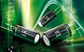 Radial (single ended) style of lithium ion capacitors for high energy density
 -
Supercapacitor/Ultracapacitor cells and modules for high current loads


| Capacitor type | Dielectric | Features/applications | Disadvantages |
|---|---|---|---|
| Supercapacitors Pseudocapacitors |
Helmholtz double-layer plus faradaic pseudo-capacitance | Energy density typically tens to hundreds of times greater than conventional electrolytics. More comparable to batteries than to other capacitors. Large capacitance/volume ratio. Relatively low ESR. Thousands of farads. RAM memory backup. Temporary power during battery replacement. Rapidly absorbs/delivers much larger currents than batteries. Hundreds of thousands of charge/discharge cycles. Hybrid vehicles. Recuperation | Polarized. Low operating voltage per cell. (Stacked cells provide higher operating voltage.) Relatively high cost. |
| Hybrid capacitors Lithium ion capacitors (LIC) |
Helmholtz double-layer plus faradaic pseudo-capacitance. Anode doped with lithium ions. | Higher operating voltage. Higher energy density than common EDLCs, but smaller than lithium ion batteries (LIB). No thermal runaway reactions. | Polarized. Low operating voltage per cell. (Stacked cells provide higher operating voltage.) Relatively high cost. |
Miscellaneous capacitors
[edit | edit source]Beneath the above described capacitors covering more or less nearly the total market of discrete capacitors some new developments or very special capacitor types as well as older types can be found in electronics.
Integrated capacitors
[edit | edit source]- Integrated capacitors—in integrated circuits, nano-scale capacitors can be formed by appropriate patterns of metallization on an isolating substrate. They may be packaged in multiple capacitor arrays with no other semiconductive parts as discrete components.[32]
- Glass capacitors—First Leyden jar capacitor was made of glass, As of 2012[update] glass capacitors were in use as SMD version for applications requiring ultra-reliable and ultra-stable service.
Power capacitors
[edit | edit source]- Vacuum capacitors—used in high power RF transmitters
- SF6 gas filled capacitors—used as capacitance standard in measuring bridge circuits
Special capacitors
[edit | edit source]- Printed circuit boards—metal conductive areas in different layers of a multi-layer printed circuit board can act as a highly stable capacitor. It is common industry practice to fill unused areas of one PCB layer with the ground conductor and another layer with the power conductor, forming a large distributed capacitor between the layers.
- Wire—2 pieces of insulated wire twisted together. Capacitance aloes usually range from 3 pF to 15 pF. Used in homemade VHF circuits for oscillation feedback.
Obsolete capacitors
[edit | edit source]- Mica capacitors—the first capacitors with stable frequency behavior and low losses, used for military radio applications during World War II
- Air-gap capacitors—used by the first spark-gap transmitters
- Miscellaneous capacitors
-
 Some 1nF × 500VDC rated silver mica capacitors
 -
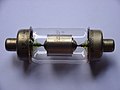 Vacuum capacitor with uranium glass encapsulation


| Capacitor type | Dielectric | Features/applications | Disadvantages |
|---|---|---|---|
| Air gap capacitors | Air | Low dielectric loss. Used for resonating HF circuits for high power HF welding. | Physically large. Relatively low capacitance. |
| Vacuum capacitors | Vacuum | Extremely low losses. Used for high voltage, high power RF applications, such as transmitters and induction heating. Self-healing if arc-over current is limited. | Very high cost. Fragile. Large. Relatively low capacitance. |
| SF6-gas filled capacitors | SF6 gas | High precision.[33] Extremely low losses. Very high stability. Up to 1600 kV rated voltage. Used as capacitance standard in measuring bridge circuits. | Very high cost |
| Metallized mica (Silver mica) capacitors | Mica | Very high stability. No aging. Low losses. Used for HF and low VHF RF circuits and as capacitance standard in measuring bridge circuits. Mostly replaced by Class 1 ceramic capacitors | Higher cost than class 1 ceramic capacitors |
| Glass capacitors | Glass | Better stability and frequency than silver mica. Ultra-reliable. Ultra-stable. Resistant to nuclear radiation. Operating temperature: −75 °C to +200 °C and even short overexposure to +250 °C.[34] | Higher cost than class 1 ceramic |
| Integrated capacitors | oxide-nitride-oxide (ONO) | Thin (down to 100 µm). Smaller footprint than most MLCC. Low ESL. Very high stability up to 200 °C. High reliability | Customized production |
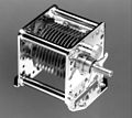
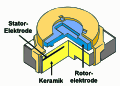
Variable capacitors
[edit | edit source]Variable capacitors may have their capacitance changed by mechanical motion. Generally two versions of variable capacitors has to be to distinguished
- Tuning capacitor – variable capacitor for intentionally and repeatedly tuning an oscillator circuit in a radio or another tuned circuit
- Trimmer capacitor – small variable capacitor usually for one-time oscillator circuit internal adjustment
Variable capacitors include capacitors that use a mechanical construction to change the distance between the plates, or the amount of plate surface area which overlaps. They mostly use air as dielectric medium.
Semiconductive variable capacitance diodes are not capacitors in the sense of passive components but can change their capacitance as a function of the applied reverse bias voltage and are used like a variable capacitor. They have replaced much of the tuning and trimmer capacitors.
- Variable capacitors
-
 Air gap tuning capacitor
 -
 Vacuum tuning capacitor
 -
 Trimmer capacitor for through hole mounting
 -
 Trimmer capacitor for surface mounting


| Capacitor type | Dielectric | Features/applications | Disadvantages |
|---|---|---|---|
| Air gap tuning capacitors | Air | Circular or various logarithmic cuts of the rotor electrode for different capacitance curves. Split rotor or stator cut for symmetric adjustment. Ball bearing axis for noise reduced adjustment. For high professional devices. | Large dimensions. High cost. |
| Vacuum tuning capacitors | Vacuum | Extremely low losses. Used for high voltage, high power RF applications, such as transmitters and induction heating. Self-healing if arc-over current is limited. | Very high cost. Fragile. Large dimensions. |
| SF6 gas filled tuning capacitor | SF6 | Extremely low losses. Used for very high voltage high power RF applications. | Very high cost, fragile, large dimensions |
| Air gap trimmer capacitors | Air | Mostly replaced by semiconductive variable capacitance diodes | High cost |
| Ceramic trimmer capacitors | Class 1 ceramic | Linear and stable frequency behavior over wide temperature range | High cost |
Market
[edit | edit source]Discrete capacitors today are industrial products produced in very large quantities for use in electronic and in electrical equipment. Globally, the market for fixed capacitors was estimated at approximately US$18 billion in 2008 for 1,400 billion (1.4 × 10¹²) pieces.[35] This market is dominated by ceramic capacitors with estimate of approximately one trillion (1 × 10¹²) items per year.[1]
Detailed estimated figures in value for the main capacitor families are:
- Ceramic capacitors—US$8.3 billion (46%);
- Aluminum electrolytic capacitors—US$ 3.9 billion (22%);
- Film capacitors and Paper capacitors—US$ 2.6 billion, (15%);
- Tantalum electrolytic capacitors—US$ 2.2 billion (12%);
- Super capacitors (Double-layer capacitors)—US$ 0.3 billion (2%); and
- Others like silver mica and vacuum capacitors—US$ 0.7 billion (3%).
All other capacitor types are negligible in terms of value and quantity compared with the above types.
Capacitor - Electrical characteristics
[edit | edit source]Series-equivalent circuit
[edit | edit source]
Discrete capacitors deviate from the ideal capacitor. An ideal capacitor only stores and releases electrical energy, with no dissipation. Capacitor components have losses and parasitic inductive parts. These imperfections in material and construction can have positive implications such as linear frequency and temperature behavior in class 1 ceramic capacitors. Conversely, negative implications include the non-linear, voltage-dependent capacitance in class 2 ceramic capacitors or the insufficient dielectric insulation of capacitors leading to leakage currents.
All properties can be defined and specified by a series equivalent circuit composed out of an idealized capacitance and additional electrical components which model all losses and inductive parameters of a capacitor. In this series-equivalent circuit the electrical characteristics are defined by:
- C, the capacitance of the capacitor
- Rinsul, the insulation resistance of the dielectric, not to be confused with the insulation of the housing
- Rleak, the resistance representing the leakage current of the capacitor
- RESR, the equivalent series resistance which summarizes all ohmic losses of the capacitor, usually abbreviated as "ESR"
- LESL, the equivalent series inductance which is the effective self-inductance of the capacitor, usually abbreviated as "ESL".
Using a series equivalent circuit instead of a parallel equivalent circuit is specified by IEC/EN 60384-1.
Standard values and tolerances
[edit | edit source]The "rated capacitance" CR or "nominal capacitance" CN is the value for which the capacitor has been designed. Actual capacitance depends on the measured frequency and ambient temperature. Standard measuring conditions are a low-voltage AC measuring method at a temperature of 20 °C with frequencies of
- 100 kHz, 1 MHz (preferred) or 10 MHz for non-electrolytic capacitors with CR ≤ 1 nF:
- 1 kHz or 10 kHz for non-electrolytic capacitors with 1 nF < CR ≤ 10 μF
- 100/120 Hz for electrolytic capacitors
- 50/60 Hz or 100/120 Hz for non-electrolytic capacitors with CR > 10 μF
For supercapacitors a voltage drop method is applied for measuring the capacitance value. .
Capacitors are available in geometrically increasing preferred values (E series standards) specified in IEC/EN 60063. According to the number of values per decade, these were called the E3, E6, E12, E24 etc. series. The range of units used to specify capacitor values has expanded to include everything from pico- (pF), nano- (nF) and microfarad (µF) to farad (F). Millifarad and kilofarad are uncommon.
The percentage of allowed deviation from the rated value is called tolerance. The actual capacitance value should be within its tolerance limits, or it is out of specification. IEC/EN 60062 specifies a letter code for each tolerance.
| E series | Tolerance | |||
|---|---|---|---|---|
| CR > 10 pF | Letter code | CR < 10 pF | Letter code | |
| E 96 | 1% | F | 0.1 pF | B |
| E 48 | 2% | G | 0.25 pF | C |
| E 24 | 5% | J | 0.5 pF | D |
| E 12 | 10% | K | 1 pF | F |
| E 6 | 20% | M | 2 pF | G |
| E3 | −20/+50% | S | - | - |
| −20/+80% | Z | - | - | |
The required tolerance is determined by the particular application. The narrow tolerances of E24 to E96 are used for high-quality circuits such as precision oscillators and timers. General applications such as non-critical filtering or coupling circuits employ E12 or E6. Electrolytic capacitors, which are often used for filtering and bypassing capacitors mostly have a tolerance range of ±20% and need to conform to E6 (or E3) series values.
Temperature dependence
[edit | edit source]Capacitance typically varies with temperature. The different dielectrics express great differences in temperature sensitivity. The temperature coefficient is expressed in parts per million (ppm) per degree Celsius for class 1 ceramic capacitors or in % over the total temperature range for all others.
| Type of capacitor, dielectric material |
Temperature coefficient ΔC/C |
Application temperature range |
|---|---|---|
| Ceramic capacitor class 1 paraelectric NP0 |
± 30 ppm/K (±0.5 %) | −55 to +125 °C |
| Ceramic capacitor class 2 ferroelectric X7R |
±15 % | −55 to +125 °C |
| Ceramic capacitor class 2, ferroelectric Y5V |
+22 % / −82 % | −30 to +85 °C |
| Film capacitor Polypropylene ( PP) |
±2.5 % | −55 to +85/105 °C |
| Film capacitor Polyethylen terephthalate, Polyester (PET) |
+5 % | −55 to +125/150 °C |
| Film capacitor Polyphenylene sulfide (PPS) |
±1.5 % | −55 to +150 °C |
| Film capacitor Polyethylene naphthalate (PEN) |
±5 % | −40 to +125/150 °C |
| Film capacitor Polytetrafluoroethylene (PTFE) |
? | −40 to +130 °C |
| Metallized paper capacitor (impregnated) | ±10 % | −25 to +85 °C |
| Aluminum electrolytic capacitor Al2O3 |
±20 % | −40 to +85/105/125 °C |
| Tantalum electrolytic capacitor Ta2O5 |
±20 % | −40 to +125 °C |
Frequency dependence
[edit | edit source]Most discrete capacitor types have more or less capacitance changes with increasing frequencies. The dielectric strength of class 2 ceramic and plastic film diminishes with rising frequency. Therefore their capacitance value decreases with increasing frequency. This phenomenon for ceramic class 2 and plastic film dielectrics is related to dielectric relaxation in which the time constant of the electrical dipoles is the reason for the frequency dependence of permittivity. The graphs below show typical frequency behavior of the capacitance for ceramic and film capacitors.
- Frequency dependence of capacitance for ceramic and film capacitors
-
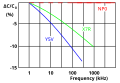 Frequency dependence of capacitance for ceramic class 2 capacitors (NP0 class 1 for comparisation)
 -
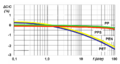 Frequency dependence of capacitance for film capacitors with different film materials


For electrolytic capacitors with non-solid electrolyte, mechanical motion of the ions occurs. Their movability is limited so that at higher frequencies not all areas of the roughened anode structure are covered with charge-carrying ions. As higher the anode structure is roughned as more the capacitance value decreases with increasing frequency. Low voltage types with highly-roughened anodes display capacitance at 100 kHz approximately 10 to 20% of the value measured at 100 Hz.
Voltage dependence
[edit | edit source]Capacitance may also change with applied voltage. This effect is more prevalent in class 2 ceramic capacitors. The permittivity of ferroelectric class 2 material depends on the applied voltage. Higher applied voltage lowers permittivity. The change of capacitance can drop to 80% of the value measured with the standardized measuring voltage of 0.5 or 1.0 V. This behavior is a small source of non-linearity in low-distortion filters and other analog applications. In audio applications this can be the reason for harmonic distortion.
Film capacitors and electrolytic capacitors have no significant voltage dependence.
- Voltage dependence of capacitance for some different class 2 ceramic capacitors
-
 Simplified diagram of the change in capacitance as a function of the applied voltage for 25-V capacitors in different kind of ceramic grades
 -
 Simplified diagram of the change in capacitance as a function of applied voltage for X7R ceramics with different rated voltages


Rated and category voltage
[edit | edit source]
The voltage at which the dielectric becomes conductive is called the breakdown voltage, and is given by the product of the dielectric strength and the separation between the electrodes. The dielectric strength depends on temperature, frequency, shape of the electrodes, etc. Because a breakdown in a capacitor normally is a short circuit and destroys the component, the operating voltage is lower than the breakdown voltage. The operating voltage is specified such that the voltage may be applied continuously throughout the life of the capacitor.
In IEC/EN 60384-1 the allowed operating voltage is called "rated voltage" or "nominal voltage". The rated voltage (UR) is the maximum DC voltage or peak pulse voltage that may be applied continuously at any temperature within the rated temperature range.
The voltage proof of nearly all capacitors decreases with increasing temperature. For some applications it is important to use a higher temperature range. Lowering the voltage applied at a higher temperature maintains safety margins. For some capacitor types therefore the IEC standard specify a second "temperature derated voltage" for a higher temperature range, the "category voltage". The category voltage (UC) is the maximum DC voltage or peak pulse voltage that may be applied continuously to a capacitor at any temperature within the category temperature range.
The relation between both voltages and temperatures is given in the picture right.
Impedance
[edit | edit source]
In general, a capacitor is seen as a storage component for electric energy. But this is only one capacitor function. A capacitor can also act as an AC resistor. In many cases the capacitor is used as a decoupling capacitor to filter or bypass undesired biased AC frequencies to the ground. Other applications use capacitors for capacitive coupling of AC signals; the dielectric is used only for blocking DC. For such applications the AC resistance is as important as the capacitance value.
The frequency dependent AC resistance is called impedance and is the complex ratio of the voltage to the current in an AC circuit. Impedance extends the concept of resistance to AC circuits and possesses both magnitude and phase at a particular frequency. This is unlike resistance, which has only magnitude.


The magnitude represents the ratio of the voltage difference amplitude to the current amplitude, is the imaginary unit, while the argument gives the phase difference between voltage and current.


In capacitor data sheets, only the impedance magnitude |Z| is specified, and simply written as "Z" so that the formula for the impedance can be written in Cartesian form

where the real part of impedance is the resistance (for capacitors ) and the imaginary part is the reactance .


As shown in a capacitor's series-equivalent circuit, the real component includes an ideal capacitor , an inductance and a resistor . The total reactance at the angular frequency therefore is given by the geometric (complex) addition of a capacitive reactance (Capacitance) and an inductive reactance (Inductance): .


To calculate the impedance the resistance has to be added geometrically and then is given by

- . The impedance is a measure of the capacitor's ability to pass alternating currents. In this sense the impedance can be used like Ohms law


to calculate either the peak or the effective value of the current or the voltage.
In the special case of resonance, in which the both reactive resistances
- and
have the same value (), then the impedance will only be determined by .


The impedance specified in the datasheets often show typical curves for the different capacitance values. With increasing frequency as the impedance decreases down to a minimum. The lower the impedance, the more easily alternating currents can be passed through the capacitor. At the apex, the point of resonance, where XC has the same value than XL, the capacitor has the lowest impedance value. Here only the ESR determines the impedance. With frequencies above the resonance the impedance increases again due to the ESL of the capacitor. The capacitor becomes to an inductance.
As shown in the graph, the higher capacitance values can fit the lower frequencies better while the lower capacitance values can fit better the higher frequencies.
Aluminum electrolytic capacitors have relatively good decoupling properties in the lower frequency range up to about 1 MHz due to their large capacitance values. This is the reason for using electrolytic capacitors in standard or switched-mode power supplies behind the rectifier for smoothing application.
Ceramic and film capacitors are already out of their smaller capacitance values suitable for higher frequencies up to several 100 MHz. They also have significantly lower parasitic inductance, making them suitable for higher frequency applications, due to their construction with end-surface contacting of the electrodes. To increase the range of frequencies, often an electrolytic capacitor is connected in parallel with a ceramic or film capacitor.[36]
Many new developments are targeted at reducing parasitic inductance (ESL). This increases the resonance frequency of the capacitor and, for example, can follow the constantly increasing switching speed of digital circuits. Miniaturization, especially in the SMD multilayer ceramic chip capacitors (MLCC), increases the resonance frequency. Parasitic inductance is further lowered by placing the electrodes on the longitudinal side of the chip instead of the lateral side. The "face-down" construction associated with multi-anode technology in tantalum electrolytic capacitors further reduced ESL. Capacitor families such as the so-called MOS capacitor or silicon capacitors offer solutions when capacitors at frequencies up to the GHz range are needed.
Inductance (ESL) and self-resonant frequency
[edit | edit source]ESL in industrial capacitors is mainly caused by the leads and internal connections used to connect the capacitor plates to the outside world. Large capacitors tend to have higher ESL than small ones because the distances to the plate are longer and every mm counts as an inductance.
For any discrete capacitor, there is a frequency above DC at which it ceases to behave as a pure capacitor. This frequency, where is as high as , is called the self-resonant frequency. The self-resonant frequency is the lowest frequency at which the impedance passes through a minimum. For any AC application the self-resonant frequency is the highest frequency at which capacitors can be used as a capacitive component.


This is critically important for decoupling high-speed logic circuits from the power supply. The decoupling capacitor supplies transient current to the chip. Without decouplers, the IC demands current faster than the connection to the power supply can supply it, as parts of the circuit rapidly switch on and off. To counter this potential problem, circuits frequently use multiple bypass capacitors—small (100 nF or less) capacitors rated for high frequencies, a large electrolytic capacitor rated for lower frequencies and occasionally, an intermediate value capacitor.
Ohmic losses, ESR, dissipation factor, and quality factor
[edit | edit source]The summarized losses in discrete capacitors are ohmic AC losses. DC losses are specified as "leakage current" or "insulating resistance" and are negligible for an AC specification. AC losses are non-linear, possibly depending on frequency, temperature, age or humidity. The losses result from two physical conditions:
- line losses including internal supply line resistances, the contact resistance of the electrode contact, line resistance of the electrodes, and in "wet" aluminum electrolytic capacitors and especially supercapacitors, the limited conductivity of liquid electrolytes and
- dielectric losses from dielectric polarization.
The largest share of these losses in larger capacitors is usually the frequency dependent ohmic dielectric losses. For smaller components, especially for wet electrolytic capacitors, conductivity of liquid electrolytes may exceed dielectric losses. To measure these losses, the measurement frequency must be set. Since commercially available components offer capacitance values cover 15 orders of magnitude, ranging from pF (10−12 F) to some 1000 F in supercapacitors, it is not possible to capture the entire range with only one frequency. IEC 60384-1 states that ohmic losses should be measured at the same frequency used to measure capacitance. These are:
- 100 kHz, 1 MHz (preferred) or 10 MHz for non-electrolytic capacitors with CR ≤ 1 nF:
- 1 kHz or 10 kHz for non-electrolytic capacitors with 1 nF < CR ≤ 10 μF
- 100/120 Hz for electrolytic capacitors
- 50/60 Hz or 100/120 Hz for non-electrolytic capacitors with CR > 10 μF
A capacitor's summarized resistive losses may be specified either as ESR, as a dissipation factor(DF, tan δ), or as quality factor (Q), depending on application requirements.
Capacitors with higher ripple current loads, such as electrolytic capacitors, are specified with equivalent series resistance ESR. ESR can be shown as an ohmic part in the above vector diagram. ESR values are specified in datasheets per individual type.

The losses of film capacitors and some class 2 ceramic capacitors are mostly specified with the dissipation factor tan δ. These capacitors have smaller losses than electrolytic capacitors and mostly are used at higher frequencies up to some hundred MHz. However the numeric value of the dissipation factor, measured at the same frequency, is independent on the capacitance value and can be specified for a capacitor series with a range of capacitance. The dissipation factor is determined as the tangent of the reactance () and the ESR, and can be shown as the angle δ between imaginary and the impedance axis.

If the inductance is small, the dissipation factor can be approximated as:


Capacitors with very low losses, such as ceramic Class 1 and Class 2 capacitors, specify resistive losses with a quality factor (Q). Ceramic Class 1 capacitors are especially suitable for LC resonant circuits with frequencies up to the GHz range, and precise high and low pass filters. For an electrically resonant system, Q represents the effect of electrical resistance and characterizes a resonator's bandwidth relative to its center or resonant frequency . Q is defined as the reciprocal value of the dissipation factor.


A high Q value is for resonant circuits a mark of the quality of the resonance.
| Capacitor type | Capacitance (pF) |
ESR at 100 kHz (mΩ) |
ESR at 1 MHz (mΩ) |
tan δ at 1 MHz (10−4) |
Quality factor |
|---|---|---|---|---|---|
| Silicon capacitor[37] | 560 | 400 | — | 2,5 | 4000 |
| Mica capacitor[38] | 1000 | 650 | 65 | 4 | 2500 |
| Class 1 ceramic capacitor (NP0)[39] |
1000 | 1600 | 160 | 10 | 1000 |
Limiting current loads
[edit | edit source]A capacitor can act as an AC resistor, coupling AC voltage and AC current between two points. Every AC current flow through a capacitor generates heat inside the capacitor body. These dissipation power loss is caused by and is the squared value of the effective (RMS) current


The same power loss can be written with the dissipation factor as


The internal generated heat has to be distributed to the ambient. The temperature of the capacitor, which is established on the balance between heat produced and distributed, shall not exceed the capacitors maximum specified temperature. Hence, the ESR or dissipation factor is a mark for the maximum power (AC load, ripple current, pulse load, etc.) a capacitor is specified for.
AC currents may be a:
- ripple current—an effective (RMS) AC current, coming from an AC voltage superimposed of an DC bias, a
- pulse current—an AC peak current, coming from an voltage peak, or an
- AC current—an effective (RMS) sinusoidal current
Ripple and AC currents mainly warms the capacitor body. By this currents internal generated temperature influences the breakdown voltage of the dielectric. Higher temperature lower the voltage proof of all capacitors. In wet electrolytic capacitors higher temperatures force the evaporation of electrolytes, shortening the life time of the capacitors. In film capacitors higher temperatures may shrink the plastic film changing the capacitor's properties.
Pulse currents, especially in metallized film capacitors, heat the contact areas between end spray (schoopage) and metallized electrodes. This may reduce the contact to the electrodes, heightening the dissipation factor.
For safe operation, the maximal temperature generated by any AC current flow through the capacitor is a limiting factor, which in turn limits AC load, ripple current, pulse load, etc.
Ripple current
[edit | edit source]A "ripple current" is the RMS value of a superimposed AC current of any frequency and any waveform of the current curve for continuous operation at a specified temperature. It arises mainly in power supplies (including switched-mode power supplies) after rectifying an AC voltage and flows as charge and discharge current through the decoupling or smoothing capacitor. The "rated ripple current" shall not exceed a temperature rise of 3, 5 or 10 °C, depending on the capacitor type, at the specified maximum ambient temperature.
Ripple current generates heat within the capacitor body due to the ESR of the capacitor. The ESR, composed out of the dielectric losses caused by the changing field strength in the dielectric and the losses resulting out of the slightly resistive supply lines or the electrolyte depends on frequency and temperature. Higher frequencies heighten the ESR and higher temperatures lower the ESR slightly.
The types of capacitors used for power applications have a specified rated value for maximum ripple current. These are primarily aluminum electrolytic capacitors, and tantalum as well as some film capacitors and Class 2 ceramic capacitors.
Aluminium electrolytic capacitors, the most common type for power supplies, experience shorter life expectancy at higher ripple currents. Exceeding the limit tends to result in explosive failure.
Tantalum electrolytic capacitors with solid manganese dioxide electrolyte are also limited by ripple current. Exceeding their ripple limits tends to shorts and burning components.
For film and ceramic capacitors, normally specified with a loss factor tan δ, the ripple current limit is determined by temperature rise in the body of approximately 10 °C. Exceeding this limit may destroy the internal structure and cause shorts.
Pulse current
[edit | edit source]The rated pulse load for a certain capacitor is limited by the rated voltage, the pulse repetition frequency, temperature range and pulse rise time. The "pulse rise time" , represents the steepest voltage gradient of the pulse (rise or fall time) and is expressed in volts per μs (V/μs).

The rated pulse rise time is also indirectly the maximum capacity of an applicable peak current . The peak current is defined as:


where: is in A; in µF; in V/µs
The permissible pulse current capacity of a metallized film capacitor generally allows an internal temperature rise of 8 to 10 °K.
In the case of metallized film capacitors, pulse load depends on the properties of the dielectric material, the thickness of the metallization and the capacitor's construction, especially the construction of the contact areas between the end spray and metallized electrodes. High peak currents may lead to selective overheating of local contacts between end spray and metallized electrodes which may destroy some of the contacts, leading to increasing ESR.
For metallized film capacitors, so-called pulse tests simulate the pulse load that might occur during an application, according to a standard specification. IEC 60384 part 1, specifies that the test circuit is charged and discharged intermittently. The test voltage corresponds to the rated DC voltage and the test comprises 10000 pulses with a repetition frequency of 1 Hz. The pulse stress capacity is the pulse rise time. The rated pulse rise time is specified as 1/10 of the test pulse rise time.
The pulse load must be calculated for each application. A general rule for calculating the power handling of film capacitors is not available because of vendor-related internal construction details. To prevent the capacitor from overheating the following operating parameters have to be considered:
- peak current per µF
- Pulse rise or fall time dv/dt in V/µs
- relative duration of charge and discharge periods (pulse shape)
- maximum pulse voltage (peak voltage)
- peak reverse voltage;
- Repetition frequency of the pulse
- Ambient temperature
- Heat dissipation (cooling)
Higher pulse rise times are permitted for pulse voltage lower than the rated voltage.
Examples for calculations of individual pulse loads are given by many manufactures, e.g. WIMA[40] and Kemet.[41]
AC current
[edit | edit source]
An AC load only can be applied to a non-polarized capacitor. Capacitors for AC applications are primarily film capacitors, metallized paper capacitors, ceramic capacitors and bipolar electrolytic capacitors.
The rated AC load for an AC capacitor is the maximum sinusoidal effective AC current (rms) which may be applied continuously to a capacitor within the specified temperature range. In the datasheets the AC load may be expressed as
- rated AC voltage at low frequencies,
- rated reactive power at intermediate frequencies,
- reduced AC voltage or rated AC current at high frequencies.

The rated AC voltage for film capacitors is generally calculated so that an internal temperature rise of 8 to 10 °K is the allowed limit for safe operation. Because dielectric losses increase with increasing frequency, the specified AC voltage has to be derated at higher frequencies. Datasheets for film capacitors specify special curves for derating AC voltages at higher frequencies.
If film capacitors or ceramic capacitors only have a DC specification, the peak value of the AC voltage applied has to be lower than the specified DC voltage.
AC loads can occur in AC Motor run capacitors, for voltage doubling, in snubbers, lighting ballast and for power factor correction PFC for phase shifting to improve transmission network stability and efficiency, which is one of the most important applications for large power capacitors. These mostly large PP film or metallized paper capacitors are limited by the rated reactive power VAr.
Bipolar electrolytic capacitors, to which an AC voltage may be applicable, are specified with a rated ripple current.
Insulation resistance and self-discharge constant
[edit | edit source]The resistance of the dielectric is finite, leading to some level of DC "leakage current" that causes a charged capacitor to lose charge over time. For ceramic and film capacitors, this resistance is called "insulation resistance Rins". This resistance is represented by the resistor Rins in parallel with the capacitor in the series-equivalent circuit of capacitors. Insulation resistance must not be confused with the outer isolation of the component with respect to the environment.
The time curve of self-discharge over insulation resistance with decreasing capacitor voltage follows the formula

With stored DC voltage and self-discharge constant


Thus, after voltage drops to 37% of the initial value.

The self-discharge constant is an important parameter for the insulation of the dielectric between the electrodes of ceramic and film capacitors. For example, a capacitor can be used as the time-determining component for time relays or for storing a voltage value as in a sample and hold circuits or operational amplifiers.
Class 1 ceramic capacitors have an insulation resistance of at least 10 GΩ, while class 2 capacitors have at least 4 GΩ or a self-discharge constant of at least 100 s. Plastic film capacitors typically have an insulation resistance of 6 to 12 GΩ. This corresponds to capacitors in the uF range of a self-discharge constant of about 2000–4000 s.[42]
Insulation resistance respectively the self-discharge constant can be reduced if humidity penetrates into the winding. It is partially strongly temperature dependent and decreases with increasing temperature. Both decrease with increasing temperature.
In electrolytic capacitors, the insulation resistance is defined as leakage current.
Leakage current
[edit | edit source]
For electrolytic capacitors the insulation resistance of the dielectric is termed "leakage current". This DC current is represented by the resistor Rleak in parallel with the capacitor in the series-equivalent circuit of electrolytic capacitors. This resistance between the terminals of a capacitor is also finite. Rleak is lower for electrolytics than for ceramic or film capacitors.
The leakage current includes all weak imperfections of the dielectric caused by unwanted chemical processes and mechanical damage. It is also the DC current that can pass through the dielectric after applying a voltage. It depends on the interval without voltage applied (storage time), the thermic stress from soldering, on voltage applied, on temperature of the capacitor, and on measuring time.
The leakage current drops in the first minutes after applying DC voltage. In this period the dielectric oxide layer can self-repair weaknesses by building up new layers. The time required depends generally on the electrolyte. Solid electrolytes drop faster than non-solid electrolytes but remain at a slightly higher level.
The leakage current in non-solid electrolytic capacitors as well as in manganese oxide solid tantalum capacitors decreases with voltage-connected time due to self-healing effects. Although electrolytics leakage current is higher than current flow over insulation resistance in ceramic or film capacitors, the self-discharge of modern non solid electrolytic capacitors takes several weeks.
A particular problem with electrolytic capacitors is storage time. Higher leakage current can be the result of longer storage times. These behaviors are limited to electrolytes with a high percentage of water. Organic solvents such as GBL do not have high leakage with longer storage times.
Leakage current is normally measured 2 or 5 minutes after applying rated voltage.
Microphonics
[edit | edit source]All ferroelectric materials exhibit piezoelectricity a piezoelectric effect. Because Class 2 ceramic capacitors use ferroelectric ceramics dielectric, these types of capacitors may have electrical effects called microphonics. Microphonics (microphony) describes how electronic components transform mechanical vibrations into an undesired electrical signal (noise).[43] The dielectric may absorb mechanical forces from shock or vibration by changing thickness and changing the electrode separation, affecting the capacitance, which in turn induces an AC current. The resulting interference is especially problematic in audio applications, potentially causing feedback or unintended recording.
In the reverse microphonic effect, varying the electric field between the capacitor plates exerts a physical force, turning them into an audio speaker. High current impulse loads or high ripple currents can generate audible sound from the capacitor itself, draining energy and stressing the dielectric.[44]
Dielectric absorption (soakage)
[edit | edit source]Dielectric absorption occurs when a capacitor that has remained charged for a long time discharges only incompletely when briefly discharged. Although an ideal capacitor would reach zero volts after discharge, real capacitors develop a small voltage from time-delayed dipole discharging, a phenomenon that is also called dielectric relaxation, "soakage" or "battery action".
| Type of capacitor | Dielectric Absorption |
|---|---|
| Air and vacuum capacitors | Not measurable |
| Class-1 ceramic capacitors, NP0 | 0.6% |
| Class-2 ceramic capacitors, X7R | 2.5% |
| Polypropylene film capacitors (PP) | 0.05 to 0.1% |
| Polyester film capacitors (PET) | 0.2 to 0.5% |
| Polyphenylene sulfide film capacitors (PPS) | 0.05 to 0.1% |
| Polyethylene naphthalate film capacitors (PEN) | 1.0 to 1.2% |
| Tantalum electrolytic capacitors with solid electrolyte | 2 to 3%,[45] 10%[46] |
| Aluminium electrolytic capacitor with non solid electrolyte | 10 to 15% |
| Double-layer capacitor or super capacitors | data not available |
In many applications of capacitors dielectric absorption is not a problem but in some applications, such as long-time-constant integrators, sample-and-hold circuits, switched-capacitor analog-to-digital converters, and very low-distortion filters, it is important that the capacitor does not recover a residual charge after full discharge, and capacitors with low absorption are specified.[47] The voltage at the terminals generated by the dielectric absorption may in some cases possibly cause problems in the function of an electronic circuit or can be a safety risk to personnel. In order to prevent shocks most very large capacitors are shipped with shorting wires that need to be removed before they are used.[48]
Energy density
[edit | edit source]The capacitance value depends on the dielectric material (ε), the surface of the electrodes (A) and the distance (d) separating the electrodes and is given by the formula of a plate capacitor:

The separation of the electrodes and the voltage proof of the dielectric material defines the breakdown voltage of the capacitor. The breakdown voltage is proportional to the thickness of the dielectric.
Theoretically, given two capacitors with the same mechanical dimensions and dielectric, but one of them have half the thickness of the dielectric. With the same dimensions this one could place twice the parallel-plate area inside. This capacitor has theoretically 4 times the capacitance as the first capacitor but half of the voltage proof.
Since the energy density stored in a capacitor is given by:

thus a capacitor having a dielectric half as thick as another has 4 times higher capacitance but ½ voltage proof, yielding an equal maximum energy density.
Therefore, dielectric thickness does not affect energy density within a capacitor of fixed overall dimensions. Using a few thick layers of dielectric can support a high voltage, but low capacitance, while thin layers of dielectric produce a low breakdown voltage, but a higher capacitance.
This assumes that neither the electrode surfaces nor the permittivity of the dielectric change with the voltage proof. A simple comparison with two existing capacitor series can show whether reality matches theory. The comparison is easy, because the manufacturers use standardized case sizes or boxes for different capacitance/voltage values within a series.
| Electrolytic capacitors NCC, KME series Ǿ D × H = 16.5 mm × 25 mm[49] |
Metallized PP film capacitors KEMET; PHE 450 series W × H × L = 10.5 mm × 20.5 mm × 31.5 mm[50] | ||
| Capacitance/Voltage | Stored Energy | Capacitance/Voltage | Stored Energy |
| 4700 µF/10 V | 235 mWs | 1.2 µF/250 V | 37.5 mWs |
| 2200 µF/25 V | 688 mWs | 0.68 µF/400 V | 54.4 mWs |
| 220 µF/100 V | 1100 mWs | 0.39 µF/630 V | 77.4 mWs |
| 22 µF/400 V | 1760 mWs | 0.27 µF/1000 V | 135 mWs |
In reality modern capacitor series do not fit the theory. For electrolytic capacitors the sponge-like rough surface of the anode foil gets smoother with higher voltages, decreasing the surface area of the anode. But because the energy increases squared with the voltage, and the surface of the anode decreases lesser than the voltage proof, the energy density increases clearly. For film capacitors the permittivity changes with dielectric thickness and other mechanical parameters so that the deviation from the theory has other reasons.[51]
Comparing the capacitors from the table with a supercapacitor, the highest energy density capacitor family. For this, the capacitor 25 F/2.3 V in dimensions D × H = 16 mm × 26 mm from Maxwell HC Series, compared with the electrolytic capacitor of approximately equal size in the table. This supercapacitor has roughly 5000 times higher capacitance than the 4700/10 electrolytic capacitor but ¼ of the voltage and has about 66,000 mWs (0.018 Wh) stored electrical energy,[52] approximately 100 times higher energy density (40 to 280 times) than the electrolytic capacitor.
Long time behavior, aging
[edit | edit source]Electrical parameters of capacitors may change over time during storage and application. The reasons for parameter changings are different, it may be a property of the dielectric, environmental influences, chemical processes or drying-out effects for non-solid materials.
Aging
[edit | edit source]
In ferroelectric Class 2 ceramic capacitors, capacitance decreases over time. This behavior is called "aging". This aging occurs in ferroelectric dielectrics, where domains of polarization in the dielectric contribute to the total polarization. Degradation of polarized domains in the dielectric decreases permittivity and therefore capacitance over time.[53][54] The aging follows a logarithmic law. This defines the decrease of capacitance as constant percentage for a time decade after the soldering recovery time at a defined temperature, for example, in the period from 1 to 10 hours at 20 °C. As the law is logarithmic, the percentage loss of capacitance will twice between 1 h and 100 h and 3 times between 1 h and 1,000 h and so on. Aging is fastest near the beginning, and the absolute capacitance value stabilizes over time.
The rate of aging of Class 2 ceramic capacitors depends mainly on its materials. Generally, the higher the temperature dependence of the ceramic, the higher the aging percentage. The typical aging of X7R ceramic capacitors is about 2.5&nbs;% per decade.[55] The aging rate of Z5U ceramic capacitors is significantly higher and can be up to 7% per decade.
The aging process of Class 2 ceramic capacitors may be reversed by heating the component above the Curie point.
Class 1 ceramic capacitors and film capacitors do not have ferroelectric-related aging. Environmental influences such as higher temperature, high humidity and mechanical stress can, over a longer period, lead to a small irreversible change in the capacitance value sometimes called aging, too.
The change of capacitance for P 100 and N 470 Class 1 ceramic capacitors is lower than 1%, for capacitors with N 750 to N 1500 ceramics it is ≤ 2%. Film capacitors may lose capacitance due to self-healing processes or gain it due to humidity influences. Typical changes over 2 years at 40 °C are, for example, ±3 % for PE film capacitors and ±1 % PP film capacitors.
Life time
[edit | edit source]
Electrolytic capacitors with non-solid electrolyte age as the electrolyte evaporates. This evaporation depends on temperature and the current load the capacitors experience. Electrolyte escape influences capacitance and ESR. Capacitance decreases and the ESR increases over time. In contrast to ceramic, film and electrolytic capacitors with solid electrolytes, "wet" electrolytic capacitors reach a specified "end of life" reaching a specified maximum change of capacitance or ESR. End of life, "load life" or "lifetime" can be estimated either by formula or diagrams[56] or roughly by a so-called "10-degree-law". A typical specification for an electrolytic capacitor states a lifetime of 2,000 hours at 85 °C, doubling for every 10 degrees lower temperature, achieving lifespan of approximately 15 years at room temperature.
Supercapacitors also experience electrolyte evaporation over time. Estimation is similar to wet electrolytic capacitors. Additional to temperature the voltage and current load influence the life time. Lower voltage than rated voltage and lower current loads as well as lower temperature extend the life time.
Failure rate
[edit | edit source]
Capacitors are reliable components with low failure rates, achieving life expectancies of decades under normal conditions. Most capacitors pass a test at the end of production similar to a "burn in", so that early failures are found during production, reducing the number of post-shipment failures.
Reliability for capacitors is usually specified in numbers of Failures In Time (FIT) during the period of constant random failures. FIT is the number of failures that can be expected in one billion (109) component-hours of operation at fixed working conditions (e.g. 1000 devices for 1 million hours, or 1 million devices for 1000 hours each, at 40 °C and 0.5 UR). For other conditions of applied voltage, current load, temperature, mechanical influences and humidity the FIT can recalculated with terms standardized for industrial[57] or military[58] contexts.
Additional information
[edit | edit source]Soldering
[edit | edit source]Capacitors may experience changes to electrical parameters due to environmental influences like soldering, mechanical stress factors (vibration, shock) and humidity. The greatest stress factor is soldering. The heat of the solder bath, especially for SMD capacitors, can cause ceramic capacitors to change contact resistance between terminals and electrodes; in film capacitors, the film may shrink, and in wet electrolytic capacitors the electrolyte may boil. A recovery period enables characteristics to stabilize after soldering; some types may require up to 24 hours. Some properties may change irreversibly by a few per cent from soldering.
Electrolytic behavior from storage or disuse
[edit | edit source]Electrolytic capacitors with non-solid electrolyte are "aged" during manufacturing by applying rated voltage at high temperature for a sufficient time to repair all cracks and weaknesses that may have occurred during production. Some electrolytes with a high water content react quite aggressively or even violently with unprotected aluminum. This leads to a "storage" or "disuse" problem of electrolytic capacitors manufactured before the 1980s. Chemical processes weaken the oxide layer when these capacitors are not used for too long. New electrolytes with "inhibitors" or "passivators" were developed during the 1980s to solve this problem.[59][60] As of 2012 the standard storage time for electronic components of two years at room temperature substantiates (cased) by the oxidation of the terminals will be specified for electrolytic capacitors with non-solid electrolytes, too. Special series for 125 °C with organic solvents like GBL are specified up to 10 years storage time ensure without pre-condition the proper electrical behavior of the capacitors.[61]
For antique radio equipment, "pre-conditioning" of older electrolytic capacitors may be recommended. This involves applying the operating voltage for some 10 minutes over a current limiting resistor to the terminals of the capacitor. Applying a voltage through a safety resistor repairs the oxide layers.
IEC/EN standards
[edit | edit source]The tests and requirements to be met by capacitors for use in electronic equipment for approval as standardized types are set out in the generic specification IEC/EN 60384-1 in the following sections.[62]
Ceramic capacitors
- IEC/EN 60384-8—Fixed capacitors of ceramic dielectric, Class 1
- IEC/EN 60384-9—Fixed capacitors of ceramic dielectric, Class 2
- IEC/EN 60384-21—Fixed surface mount multilayer capacitors of ceramic dielectric, Class 1
- IEC/EN 60384-22—Fixed surface mount multilayer capacitors of ceramic dielectric, Class 2
Film capacitors
- IEC/EN 60384-2—Fixed metallized polyethylene-terephthalate film dielectric d.c. capacitors
- IEC/EN 60384-11—Fixed polyethylene-terephthalate film dielectric metal foil d.c. capacitors
- IEC/EN 60384-13—Fixed polypropylene film dielectric metal foil d.c. capacitors
- IEC/EN 60384-16—Fixed metallized polypropylene film dielectric d.c. capacitors
- IEC/EN 60384-17—Fixed metallized polypropylene film dielectric a.c. and pulse
- IEC/EN 60384-19—Fixed metallized polyethylene-terephthalate film dielectric surface mount d.c. capacitors
- IEC/EN 60384-20—Fixed metalized polyphenylene sulfide film dielectric surface mount d.c. capacitors
- IEC/EN 60384-23—Fixed metallized polyethylene naphthalate film dielectric chip d.c. capacitors
Electrolytic capacitors
- IEC/EN 60384-3—Surface mount fixed tantalum electrolytic capacitors with manganese dioxide solid electrolyte
- IEC/EN 60384-4—Aluminium electrolytic capacitors with solid (MnO2) and non-solid electrolyte
- IEC/EN 60384-15—fixed tantalum capacitors with non-solid and solid electrolyte
- IEC/EN 60384-18—Fixed aluminium electrolytic surface mount capacitors with solid (MnO2) and non-solid electrolyte
- IEC/EN 60384-24—Surface mount fixed tantalum electrolytic capacitors with conductive polymer solid electrolyte
- IEC/EN 60384-25—Surface mount fixed aluminium electrolytic capacitors with conductive polymer solid electrolyte
Supercapacitors
- IEC/EN 62391-1—Fixed electric double-layer capacitors for use in electric and electronic equipment - Part 1: Generic specification
- IEC/EN 62391-2—Fixed electric double-layer capacitors for use in electronic equipment - Part 2: Sectional specification - Electric double-layer capacitors for power application
Capacitor symbols
[edit | edit source]
|
|||||
| Capacitor | Polarized capacitor Electrolytic capacitor |
Bipolar electrolytic capacitor |
Feed through capacitor |
Tuning variable capacitor |
Trimmer variable capacitor |
Markings
[edit | edit source]Imprinted
[edit | edit source]Capacitors, like most other electronic components and if enough space is available, have imprinted markings to indicate manufacturer, type, electrical and thermal characteristics, and date of manufacture. If they are large enough the capacitor is marked with:
- manufacturer's name or trademark;
- manufacturer's type designation;
- polarity of the terminations (for polarized capacitors)
- rated capacitance;
- tolerance on rated capacitance
- rated voltage and nature of supply (AC or DC)
- climatic category or rated temperature;
- year and month (or week) of manufacture;
- certification marks of safety standards (for safety EMI/RFI suppression capacitors)
Polarized capacitors have polarity markings, usually "-" (minus) sign on the side of the negative electrode for electrolytic capacitors or a stripe or "+" (plus) sign, see #Polarity marking. Also, the negative lead for leaded "wet" e-caps is usually shorter.
Smaller capacitors use a shorthand notation. The most commonly used format is: XYZ J/K/M VOLTS V, where XYZ represents the capacitance (calculated as XY × 10Z pF), the letters J, K or M indicate the tolerance (±5%, ±10% and ±20% respectively) and VOLTS V represents the working voltage.
Examples:
- 105K 330V implies a capacitance of 10 × 105 pF = 1 µF (K = ±10%) with a working voltage of 330 V.
- 473M 100V implies a capacitance of 47 × 103 pF = 47 nF (M = ±20%) with a working voltage of 100 V.
Capacitance, tolerance and date of manufacture can be indicated with a short code specified in IEC/EN 60062. Examples of short-marking of the rated capacitance (microfarads): µ47 = 0,47 µF, 4µ7 = 4,7 µF, 47µ = 47 µF
The date of manufacture is often printed in accordance with international standards.
- Version 1: coding with year/week numeral code, "1208" is "2012, week number 8".
- Version 2: coding with year code/month code. The year codes are: "R" = 2003, "S"= 2004, "T" = 2005, "U" = 2006, "V" = 2007, "W" = 2008, "X" = 2009, "A" = 2010, "B" = 2011, "C" = 2012, "D" = 2013, etc. Month codes are: "1" to "9" = Jan. to Sept., "O" = October, "N" = November, "D" = December. "X5" is then "2009, May"
For very small capacitors like MLCC chips no marking is possible. Here only the traceability of the manufacturers can ensure the identification of a type.
Colour coding
[edit | edit source]As of 2013[update] Capacitors do not use color coding.
Polarity marking
[edit | edit source]- Polarity marking
-

-

-


Aluminum e-caps with non-solid electrolyte have a polarity marking at the cathode (minus) side. Aluminum, tantalum, and niobium e-caps with solid electrolyte have a polarity marking at the anode (plus) side. Supercapacitor are marked at the minus side.
Footnotes
[edit | edit source]- ↑ a b J. Ho, T. R. Jow, S. Boggs, Historical Introduction to Capacitor Technology, PDF [1]
- ↑ a b c Adam Marcus Namisnyk (2003-07-23). "A Survey of Electrochemical Supercapacitor Technology" (PDF). Retrieved 2011-06-24. Invalid
<ref>tag; name "Namisnyk" defined multiple times with different content - ↑ WIMA, Characteristics of Metallized Film Capacitors in Comparison with Other Dielectrics [2]
- ↑ Film Capacitors, TDK Epcos, General technical information
- ↑ AVX, Dielectric Comparison Chart
- ↑ Holystone, Capacitor Dielectric Comparison, Technical Note 3
- ↑ Power Film Capacitors for Industrial Applications, P. Bettacchi, D. Montanari, D. Zanarini, D. Orioli, G. Rondelli, A. Sanua, KEMET Electronics [3]
- ↑ a b Template:Literatur
- ↑ General technical information of (RFI/EMI)Noise suppression capacitors on AC mains [4]
- ↑ Vishay, Capacitors - RFI Class X/Y
- ↑ X2Y® Technology
- ↑ Murata, Three-terminal Capacitor Structure, No.TE04EA-1.pdf 98.3.20
- ↑ Vishay, Ceramic RF-Power Capacitors
- ↑ Vishay. "Capacitors - RF Power". Vishay. Retrieved 2013-03-09.
- ↑ Passive component magazine, Nov./Dec. 2005, F. Jacobs, Polypropylene Capacitor Film Resin, p. 29 ff [5]
- ↑ Paumanok Publications, PCInewsletterOct2007cmp Paumanok Publications, Inc.
- ↑ WIMA, RFI Capacitors
- ↑ WIMA Snubber Capacitors
- ↑ Amrad Engeneering Inc., Motor run capacitors
- ↑ Epcos, Capacitors for power electronics, General technical information
- ↑ Sanyo, Capacitor lecture POSCAP (Ta) (Basic), Polymerized electrolyte
- ↑ CDE, Motor Start Capacitors
- ↑ Rubycon, Aluminum Electrolytic Capacitors for Strobe Flash
- ↑ Fischer & Tausche, Electrolytic capacitor for audio frequency
- ↑ Vishay, Wet Electrolyte Tantalum Capacitors, Introduction
- ↑ Self-healing Characteristics of Solid Electrolytic Capacitor with Polypyrrole Electrolyte, Yamamoto Hideo [6]
- ↑ a b c B. E. Conway (1999). Electrochemical Supercapacitors: Scientific Fundamentals and Technological Applications. Berlin: Springer. ISBN 0306457369. Retrieved 2013-05-02. see also Brian E. Conway in Electrochemistry Encyclopedia: Electrochemical Capacitors — Their Nature, Function and Applications
- ↑ Template:Cite techreport
- ↑ Elzbieta Frackowiak, Francois Beguin, PERGAMON, Carbon 39 (2001) 937–950, Carbon materials for the electrochemical storage of energy in Capacitors
- ↑ Yu.M. Volfkovich, A.A. Mikhailin, D.A. Bograchev, V.E. Sosenkin and V.S. Bagotsky, Studies of Supercapacitor Carbon Electrodes with High Pseudocapacitance, A. N. Frumkin Institute of Physical Chemistry and Electrochemistry, Russian Academy of Sciences, Moscow, Russia, Dr. Ujjal Kumar Sur (Ed.), ISBN 978-953-307-830-4
- ↑ Elton
- ↑ IPDiA, 3D Silicon Capacitors
- ↑ Tettex instruments, SF6 Gas insulated Standard Capacitors
- ↑ AVX, Performance Characteristics of Multilayer Glass Capacitors
- ↑ highbeam business, Electronic Capacitors SIC 3675, Industry report
- ↑ Murata: Basics of capacitors, lesson 2 Includes graph showing impedance as a function of frequency for different capacitor types; electrolytics are the only ones with a large component due to ESR
- ↑ Siliziumkondensator, Vishay, HPC0603A
- ↑ Simic Electronics, Chip Mica Capacitors
- ↑ AVX, NP0, 1000 pF 100 V, 0805, Q >= 1000 (1 MHz), [7]
- ↑ WIMA, Selection of Capacitors for Pulse Applications
- ↑ Kemet, General information DC Film Capacitors
- ↑ Wima,Insulation Resistance
- ↑ [8], Capacitors for reduced sound emissions.
- ↑ Kemet, Are your military ceramic capacitors subject to the piezoelectric effect? [9]
- ↑ Kemet, Polymer Tantalum Chip Capacitors
- ↑ AVX, ANALYSIS OF SOLID TANTALUM CAPACITOR LEAKAGE CURRENT
- ↑ "Understand Capacitor Soakage to Optimize Analog Systems" by Bob Pease 1982 [10]
- ↑ * "Modeling Dielectric Absorption in Capacitors", by Ken Kundert
- ↑ NCC, KME series
- ↑ KEMET, series PHE450
- ↑ Metallized Polypropylene Film Energy Storage Capacitors For Low Pulse Duty, Ralph M. Kerrigan, NWL Capacitor Division [11]
- ↑ Maxwell HC Series / docs/datasheet_hc_series_1013793.pdf
- ↑ Template:Literatur
- ↑ Takaaki Tsurumi & Motohiro Shono & Hirofumi Kakemoto & Satoshi Wada & Kenji Saito & Hirokazu Chazono, Mechanism of capacitance aging under DC-bias field in X7R-MLCCs Published online: 23 March 2007, # Springer Science + Business Media, LLC 2007 [12]
- ↑ Christopher England, Johanson dielectrics, Ceramic Capacitor Aging Made Simple [13]
- ↑ Electrolytic Capacitor Lifetime Estimation, Dr. Arne Albertsen, Jianghai Europe, [14]
- ↑ IEC/EN 61709, Electric components. Reliability. Reference conditions for failure rates and stress models for conversion
- ↑ MIL-HDBK-217F Reliability Prediction of Electronic Equipment
- ↑ J. L. Stevens, T. R. Marshall, A. C. Geiculescu M., C. R. Feger, T. F. Strange, Carts USA 2006, The Effects of Electrolyte Composition on the Deformation Characteristics of Wet Aluminum ICD Capacitors, [15]
- ↑ Alfonso Berduque, Zongli Dou, Rong Xu, BHC Components Ltd (KEMET), Electrochemical Studies for Aluminium Electrolytic Capacitor Applications: Corrosion Analysis of Aluminium in Ethylene Glycol-Based Electrolytes pdf
- ↑ Vishay BCcomponents, Introduction Aluminum Capacitors, paragraph "Storage", Revision: 10-May-12, Document Number: 28356, pdf
- ↑ IEC/EN/DIN Standards, Beuth-Verlag