
Signetics 2650 & 2636 programming/Sound
The sounds circuits vary somewhat between manufacturers. At present the information given here applies only to the Videomaster/Voltmace Database. The general use of the bits in register $1E80 are fairly consistent, but the precise effects might vary. |
The sound on these consoles is quite rudimentary; just one channel of square wave that can be modified by analog circuits to add white noise, explosion sound and select one-of-four volume levels.
The square wave is generated by the PVI. Programming a non-zero eight-bit integer n into its register $1FC7 generates a square wave of 128(n+1)μs. Programming that register with zero inhibits square wave generation. When the register is changed while audio is being output, the change will not become effective until the next negative or positive transition of the audio signal.
The PVI audio frequency chart lists the frequencies attainable. The frequencies do not match the A440 pitch standard, though most notes are within ±2% and are probably not noticeably different. Above D5, many notes are just not obtainable, and in octave 7 the only notes are B and E.
The square wave is fed to some audio effects circuits that are controlled from the microprocessor via the 74LS378 effects register at address $1E80. These circuits can:
- set one of four volume levels
- cause an explosion sound
- turn on white noise
- turn the PVI tone on/off
| 7 | 6 | 5 | 4 | 3 | 2 | 1 | 0 |
|---|---|---|---|---|---|---|---|
| Attenuation | Invert | Explosion | Noise | PVI tone | - | - | |
Attenuation
[edit | edit source]
When the Attenuation bits are set to 00, the volume is its highest.
| bit 7 | bit 6 | Relative volume, p-p* |
|---|---|---|
| 0 | 0 | 1 |
| 0 | 1 | 0.65 |
| 1 | 0 | 0.40 |
| 1 | 1 | 0.25 |
* These peak-to-peak voltage measurements were taken on a Voltmace Database on pin 14 of the op-amp, IC9.
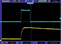
The oscilloscope trace here is taken at the junction of C25 and R59. At the first step, the PVI tone (bit 2) is turned off. In subsequent steps it is turned on, and the attenuation is increased at each step. The attenuation shifts the dc level of the signal as well as changing the peak-to-peak voltage of the signal.
Invert
[edit | edit source]The Invert bit affects the colour output, see Programming colours.
Explosion
[edit | edit source]When the Explosion bit is set to 1, an RC circuit is charged and mixed with the white noise signal. As the RC circuit discharges the volume of the white noise decreases over a period of about 1.6 seconds. The RC circuit takes about 5ms to fully charge and does not start to discharge until bit 4 goes low. If bit 4 is held high for a period less than 5ms, it is possible to reduce the volume and duration of the explosion.
-
 Charge and decay of the RC circuit (yellow) that generates an explosion sound. Bit 4 (blue) is held high for 20ms.
 -
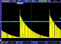 Output of explosion circuit (yellow) after a full charge (blue) of 20ms.
 -
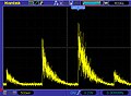 Output of explosion circuit with bit 4 held high for 220μs, 2.8ms and 6.6ms respectively.


These next two bits don't behave quite how we might like them to:
Noise
[edit | edit source]
Bit 3 of the effects register superimposes white noise on the positive half-cycle of the tone from the PVI.
PVI tone
[edit | edit source]Bit 2 enables the PVI tone when it is high. When set low, the PVI tone is switched off.
One quirk of the Database circuitry is that when the white noise is turned on and PVI tone is off, the tone is only reduced to about half-volume rather than being switched off altogether.