Plastics Molding & Manufacturing/Mould System
Molding system
[edit | edit source]The mold consists of many different components, but the primary components are the side A and side plates.
 The top half is Side A meanwhile the bottom half is Side B
Side A - The half cavity is located here where the plastic materials are injected here running through sprue and gate
Side B - The ejector pin is located here to push the molded parts out from mold
The picture above shows a typical plastic product that are moulded from injection moulding.

Components in Molding System
[edit | edit source]Sprue Bushing
[edit | edit source]The primary functions is to seal tightly against the nozzle of the injection barrel of the molding machine and to allow molten plastic to flow from the barrel into the mold. There is a tapered hole in the middle of the sprue bushing and that is where the plastic flows through the bushing. The hole is tapered to allow the plastic, after it solidifies, to be removed easily to prepare for the next cycle.
-
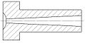 Sprue bush Type A
 -
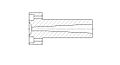 Sprue bush Type B
 -
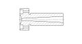 Sprue bush Type C
 -
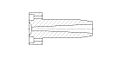 Sprue bush Type D


Runner
[edit | edit source]The molten plastic are directed to the cavity images through channels that are machined into the faces of the A and B plates. These channels allow plastic to run along them, so they are referred to as runners. To save material and cycle time, many molds are built with hot runner systems A runner shaped as full round is ideal case. This is because a circular cross section creates equal pressure in all directions on the plastic molecules, while a non-circular section causes unequal pressure
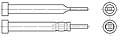
Ejector Pins
[edit | edit source]When the mold opens, the finished part is pushed out by a number of ejector pins shaped like flat headed pins.The ejector will pushes out the products from the mold after cooling phase
-
 Ejector pin Type A
 -
 Ejector pin Type B
 -
 Ejector pin Type C
 -
 Ejector pin Type D
 -
 Ejector sleeve