OpenSCAD User Manual/Primitive Solids
cube
[edit | edit source]Creates a cube or rectangular prism (i.e., a "box") in the first octant. When center is true, the cube is centered on the origin. Argument names are optional if given in the order shown here.
cube(size = [x,y,z], center = true/false);
cube(size =  x ,     center = true/false);
- parameters:
- size
- single value, cube with all sides this length
- 3 value array [x,y,z], rectangular prism with dimensions x, y and z.
- center
- false (default), 1st (positive) octant, one corner at (0,0,0)
- true, cube is centered at (0,0,0)
- size
default values: cube(); yields: cube(size = [1, 1, 1], center = false);
- examples:

equivalent scripts for this example
 cube(size = 18);
 cube(18);
 cube([18,18,18]);
 .
 cube(18,false);
 cube([18,18,18],false);
 cube([18,18,18],center=false);
 cube(size = [18,18,18], center = false);
 cube(center = false,size = [18,18,18] );

equivalent scripts for this example
 cube([18,28,8],true);
 box=[18,28,8];cube(box,true);
sphere
[edit | edit source]Creates a sphere at the origin of the coordinate system. The r argument name is optional. To use d instead of r, d must be named.
Parameters
- r
- Radius. This is the radius of the sphere. The resolution of the sphere is based on the size of the sphere and the $fa, $fs and $fn variables. For more information on these special variables look at: OpenSCAD_User_Manual/Other_Language_Features
- d
- Diameter. This is the diameter of the sphere.
- $fa
- Fragment angle in degrees
- $fs
- Fragment size in mm
- $fn
- Resolution
default values: sphere(); yields: sphere($fn = 0, $fa = 12, $fs = 2, r = 1);
Usage Examples
sphere(r = 1);
sphere(r = 5);
sphere(r = 10);
sphere(d = 2);
sphere(d = 10);
sphere(d = 20);
// this creates a high resolution sphere with a 2mm radius
sphere(2, $fn=100);
// also creates a 2mm high resolution sphere but this one
// does not have as many small triangles on the poles of the sphere
sphere(2, $fa=5, $fs=0.1);

cylinder
[edit | edit source]Creates a cylinder or cone centered about the z axis. When center is true, it is also centered vertically along the z axis.
Parameter names are optional if given in the order shown here. If a parameter is named, all following parameters must also be named.
cylinder(h = height, r1 = BottomRadius, r2 = TopRadius, center = true/false);
NOTES:
The 2nd & 3rd positional parameters are r1 & r2, if r, d, d1 or d2 are used they must be named.
Using r1 & r2 or d1 & d2 with either value of zero will make a cone shape, a non-zero non-equal value will produce a section of a cone (a Conical Frustum). r1 & d1 define the base width, at [0,0,0], and r2 & d2 define the top width.
- Parameters
- h : height of the cylinder or cone
- r : radius of cylinder. r1 = r2 = r.
- r1 : radius, bottom of cone.
- r2 : radius, top of cone.
- d : diameter of cylinder. r1 = r2 = d / 2. [Note: Requires version 2014.03]
- d1 : diameter, bottom of cone. r1 = d1 / 2. [Note: Requires version 2014.03]
- d2 : diameter, top of cone. r2 = d2 / 2. [Note: Requires version 2014.03]
- center
- false (default), z ranges from 0 to h
- true, z ranges from -h/2 to +h/2
- $fa : minimum angle (in degrees) of each fragment.
- $fs : minimum circumferential length of each fragment.
- $fn : fixed number of fragments in 360 degrees. Values of 3 or more override $fa and $fs
- $fa, $fs and $fn must be named parameters. click here for more details,.
defaults: cylinder(); yields: cylinder($fn = 0, $fa = 12, $fs = 2, h = 1, r1 = 1, r2 = 1, center = false);

equivalent scripts
 cylinder(h=15, r1=9.5, r2=19.5, center=false);
 cylinder(  15,    9.5,    19.5, false);
 cylinder(  15,    9.5,    19.5);
 cylinder(  15,    9.5, d2=39  );
 cylinder(  15, d1=19,  d2=39  );
 cylinder(  15, d1=19,  r2=19.5);

equivalent scripts
 cylinder(h=15, r1=10, r2=0, center=true);
 cylinder(  15,    10,    0,        true);
 cylinder(h=15, d1=20, d2=0, center=true);
-
 center = false
 -
 center = true


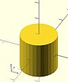
equivalent scripts
 cylinder(h=20, r=10, center=true);
 cylinder(  20,   10, 10,true);
 cylinder(  20, d=20, center=true);
 cylinder(  20,r1=10, d2=20, center=true);
 cylinder(  20,r1=10, d2=2*10, center=true);
- use of $fn
Larger values of $fn create smoother, more circular, surfaces at the cost of longer rendering time. Some use medium values during development for the faster rendering, then change to a larger value for the final F6 rendering.
However, use of small values can produce some interesting non circular objects. A few examples are show here:


scripts for these examples
 cylinder(20,20,20,$fn=3);
 cylinder(20,20,00,$fn=4);
 cylinder(20,20,10,$fn=4);
- undersized holes
Using cylinder() with difference() to place holes in objects creates undersized holes. This is because circular paths are approximated with polygons inscribed within in a circle. The points of the polygon are on the circle, but straight lines between are inside. To have all of the hole larger than the true circle, the polygon must lie wholly outside of the circle (circumscribed). Modules for circumscribed holes

script for this example
 poly_n = 6;
 color("blue") translate([0, 0, 0.02]) linear_extrude(0.1) circle(10, $fn=poly_n);
 color("green") translate([0, 0, 0.01]) linear_extrude(0.1) circle(10, $fn=360);
 color("purple") linear_extrude(0.1) circle(10/cos(180/poly_n), $fn=poly_n);
In general, a polygon of radius has a radius to the midpoint of any side as . If only the midpoint radius is known (for example, to fit a hex key into a hexagonal hole), then the polygon radius is .


polyhedron
[edit | edit source]A polyhedron is the most general 3D primitive solid. It can be used to create any regular or irregular shape including those with concave as well as convex features. Curved surfaces are approximated by a series of flat surfaces.
polyhedron( points = [ [X0, Y0, Z0], [X1, Y1, Z1], ... ], triangles = [ [P0, P1, P2], ... ], convexity = N);   // before 2014.03
polyhedron( points = [ [X0, Y0, Z0], [X1, Y1, Z1], ... ], faces = [ [P0, P1, P2, P3, ...], ... ], convexity = N);   // 2014.03 & later
- Parameters
- points
- Vector of 3d points or vertices. Each point is in turn a vector, [x,y,z], of its coordinates.
- Points may be defined in any order. N points are referenced, in the order defined, as 0 to N-1.
- points
- triangles [Deprecated: triangles will be removed in future releases. Use faces parameter instead]
- Vector of faces that collectively enclose the solid. Each face is a vector containing the indices (0 based) of 3 points from the points vector.
- triangles [Deprecated: triangles will be removed in future releases. Use faces parameter instead]
- faces [Note: Requires version 2014.03]
- Vector of faces that collectively enclose the solid. Each face is a vector containing the indices (0 based) of 3 or more points from the points vector.
- Faces may be defined in any order, but the points of each face must be ordered correctly (see below). Define enough faces to fully enclose the solid, with no overlap.
- If points that describe a single face are not on the same plane, the face is automatically split into triangles as needed.
- faces [Note: Requires version 2014.03]
- convexity
- Integer. The convexity parameter specifies the maximum number of faces a ray intersecting the object might penetrate. This parameter is needed only for correct display of the object in OpenCSG preview mode. It has no effect on the polyhedron rendering. For display problems, setting it to 10 should work fine for most cases.
- convexity
default values: polyhedron(); yields: polyhedron(points = undef, faces = undef, convexity = 1);
In the list of faces, for each face it is arbitrary which point you start with, but the points of the face (referenced by the index into the list of points) must be ordered in clockwise direction when looking at each face from outside inward. The back is viewed from the back, the bottom from the bottom, etc. Another way to remember this ordering requirement is to use the right-hand rule. Using your right-hand, stick your thumb up and curl your fingers as if giving the thumbs-up sign, point your thumb into the face, and order the points in the direction your fingers curl. Try this on the example below.
- Example 1 Using polyhedron to generate cube( [ 10, 7, 5 ] );


CubePoints = [
  [  0,  0,  0 ],  //0
  [ 10,  0,  0 ],  //1
  [ 10,  7,  0 ],  //2
  [  0,  7,  0 ],  //3
  [  0,  0,  5 ],  //4
  [ 10,  0,  5 ],  //5
  [ 10,  7,  5 ],  //6
  [  0,  7,  5 ]]; //7

CubeFaces = [
  [0,1,2,3],  // bottom
  [4,5,1,0],  // front
  [7,6,5,4],  // top
  [5,6,2,1],  // right
  [6,7,3,2],  // back
  [7,4,0,3]]; // left

polyhedron( CubePoints, CubeFaces );
equivalent descriptions of the bottom face
  [0,1,2,3],
  [0,1,2,3,0],
  [1,2,3,0],
  [2,3,0,1],
  [3,0,1,2],
  [0,1,2],[2,3,0],   // 2 triangles with no overlap
  [1,2,3],[3,0,1],
  [1,2,3],[0,1,3],
- Example 2 A square base pyramid:

polyhedron(
  points=[ [10,10,0],[10,-10,0],[-10,-10,0],[-10,10,0], // the four points at base
           [0,0,10]  ],                                 // the apex point
  faces=[ [0,1,4],[1,2,4],[2,3,4],[3,0,4],              // each triangle side
              [1,0,3],[2,1,3] ]                         // two triangles for square base
 );
- Example 3 A triangular prism:
Note: There is an error in this example, a steely-eyed CAD Man noticed the unfolded triangles are incorrect, the hypotenuse should be 1,5 & 0,4.
The correct unfold is to have them next to rectangle A, along sides 1,2 & 0,3. The code has been corrected, hopefully a revised image will arrive in due course.

  module prism(l, w, h){
      polyhedron(//pt 0        1        2        3        4        5
              points=[[0,0,0], [l,0,0], [l,w,0], [0,w,0], [0,w,h], [l,w,h]],
              faces=[[0,1,2,3],[5,4,3,2],[0,4,5,1],[0,3,4],[5,2,1]]
              );

      // preview unfolded (do not include in your function
      z = 0.08;
      separation = 2;
      border = .2;
      translate([0,w+separation,0])
          cube([l,w,z]);
      translate([0,w+separation+w+border,0])
          cube([l,h,z]);
      translate([0,w+separation+w+border+h+border,0])
          cube([l,sqrt(w*w+h*h),z]);
      translate([l+border,w+separation,0])
          polyhedron(//pt 0       1       2        3       4       5
                  points=[[0,0,0],[h,w,0],[0,w,0], [0,0,z],[h,w,z],[0,w,z]],
                  faces=[[0,1,2], [3,5,4], [0,3,4,1], [1,4,5,2], [2,5,3,0]]
                  );
      translate([0-border,w+separation,0])
          polyhedron(//pt 0       1         2        3       4         5
                  points=[[0,0,0],[0-h,w,0],[0,w,0], [0,0,z],[0-h,w,z],[0,w,z]],
                  faces=[[1,0,2],[5,3,4],[0,1,4,3],[1,2,5,4],[2,0,3,5]]
                  );
      }

  prism(10, 5, 3);
Debugging polyhedra
[edit | edit source]Mistakes in defining polyhedra include not having all faces in clockwise order (viewed from outside - a bottom need to be viewed from below), overlap of faces and missing faces or portions of faces. As a general rule, the polyhedron faces should also satisfy manifold conditions:
- exactly two faces should meet at any polyhedron edge.
- if two faces have a vertex in common, they should be in the same cycle face-edge around the vertex.
The first rule eliminates polyhedra like two cubes with a common edge and not watertight models; the second excludes polyhedra like two cubes with a common vertex.
When viewed from the outside, the points describing each face must be in the same clockwise order, and provides a mechanism for detecting counterclockwise. When the thrown together view (F12) is used with F5, CCW faces are shown in pink. Reorder the points for incorrect faces. Rotate the object to view all faces. The pink view can be turned off with F10.
OpenSCAD allows, temporarily, commenting out part of the face descriptions so that only the remaining faces are displayed. Use // to comment out the rest of the line. Use /* and */ to start and end a comment block. This can be part of a line or extend over several lines. Viewing only part of the faces can be helpful in determining the right points for an individual face. Note that a solid is not shown, only the faces. If using F12, all faces have one pink side. Commenting some faces helps also to show any internal face.

CubeFaces = [
/* [0,1,2,3],  // bottom
   [4,5,1,0],  // front */
   [7,6,5,4],  // top
/* [5,6,2,1],  // right
   [6,7,3,2],  // back */
   [7,4,0,3]]; // left
After defining a polyhedron, its preview may seem correct. The polyhedron alone may even render fine. However, to be sure it is a valid manifold and that it can generate a valid STL file, union it with any cube and render it (F6). If the polyhedron disappears, it means that it is not correct. Revise the winding order of all faces and the two rules stated above.
Mis-ordered faces
[edit | edit source]- Example 4 a more complex polyhedron with mis-ordered faces
When you select 'Thrown together' from the view menu and compile (preview F5) the design (not compile and render!) the preview shows the mis-oriented polygons highlighted. Unfortunately this highlighting is not possible in the OpenCSG preview mode because it would interfere with the way the OpenCSG preview mode is implemented.)
Below you can see the code and the picture of such a problematic polyhedron, the bad polygons (faces or compositions of faces) are in pink.
// Bad polyhedron
polyhedron
    (points = [
	       [0, -10, 60], [0, 10, 60], [0, 10, 0], [0, -10, 0], [60, -10, 60], [60, 10, 60],
	       [10, -10, 50], [10, 10, 50], [10, 10, 30], [10, -10, 30], [30, -10, 50], [30, 10, 50]
	       ],
     faces = [
		  [0,2,3],   [0,1,2],  [0,4,5],  [0,5,1],   [5,4,2],  [2,4,3],
                  [6,8,9],  [6,7,8],  [6,10,11], [6,11,7], [10,8,11],
		  [10,9,8], [0,3,9],  [9,0,6], [10,6, 0],  [0,4,10],
                  [3,9,10], [3,10,4], [1,7,11],  [1,11,5], [1,7,8],
                  [1,8,2],  [2,8,11], [2,11,5]
		  ]
     );

A correct polyhedron would be the following:
polyhedron
    (points = [
	       [0, -10, 60], [0, 10, 60], [0, 10, 0], [0, -10, 0], [60, -10, 60], [60, 10, 60],
	       [10, -10, 50], [10, 10, 50], [10, 10, 30], [10, -10, 30], [30, -10, 50], [30, 10, 50]
	       ],
     faces = [
		  [0,3,2],  [0,2,1],  [4,0,5],  [5,0,1],  [5,2,4],  [4,2,3],
                  [6,8,9],  [6,7,8],  [6,10,11],[6,11,7], [10,8,11],
		  [10,9,8], [3,0,9],  [9,0,6],  [10,6, 0],[0,4,10],
                  [3,9,10], [3,10,4], [1,7,11], [1,11,5], [1,8,7],
                  [2,8,1],  [8,2,11], [5,11,2]
		  ]
     );
- Beginner's tip
If you don't really understand "orientation", try to identify the mis-oriented pink faces and then invert the sequence of the references to the points vectors until you get it right. E.g. in the above example, the third triangle ([0,4,5]) was wrong and we fixed it as [4,0,5]. Remember that a face list is a circular list. In addition, you may select "Show Edges" from the "View Menu", print a screen capture and number both the points and the faces. In our example, the points are annotated in black and the faces in blue. Turn the object around and make a second copy from the back if needed. This way you can keep track.
- Clockwise technique
Orientation is determined by clockwise circular indexing. This means that if you're looking at the triangle (in this case [4,0,5]) from the outside you'll see that the path is clockwise around the center of the face. The winding order [4,0,5] is clockwise and therefore good. The winding order [0,4,5] is counter-clockwise and therefore bad. Likewise, any other clockwise order of [4,0,5] works: [5,4,0] & [0,5,4] are good too. If you use the clockwise technique, you'll always have your faces outside (outside of OpenSCAD, other programs do use counter-clockwise as the outside though).
Think of it as a "left hand rule":
If you place your left hand on the face with your fingers curled in the direction of the order of the points, your thumb should point outward. If your thumb points inward, you need to reverse the winding order.

Succinct description of a 'Polyhedron'
- Points define all of the points/vertices in the shape.
- Faces is a list of polygons that connect up the points/vertices.
Each point, in the point list, is defined with a 3-tuple x,y,z position specification. Points in the point list are automatically enumerated starting from zero for use in the faces list (0,1,2,3,... etc).
Each face, in the faces list, is defined by selecting 3 or more of the points (using the point order number) out of the point list.
e.g. faces=[ [0,1,2] ] defines a triangle from the first point (points are zero referenced) to the second point and then to the third point.
When looking at any face from the outside, the face must list all points in a clockwise order.
Point repetitions in a polyhedron point list
[edit | edit source]The point list of the polyhedron definition may have repetitions. When two or more points have the same coordinates they are considered the same polyhedron vertex. So, the following polyhedron:
points = [[ 0, 0, 0], [10, 0, 0], [ 0,10, 0],
          [ 0, 0, 0], [10, 0, 0], [ 0,10, 0],
          [ 0,10, 0], [10, 0, 0], [ 0, 0,10],
          [ 0, 0, 0], [ 0, 0,10], [10, 0, 0],
          [ 0, 0, 0], [ 0,10, 0], [ 0, 0,10]];
polyhedron(points, [[0,1,2], [3,4,5], [6,7,8], [9,10,11], [12,13,14]]);
define the same tetrahedron as:
points = [[0,0,0], [0,10,0], [10,0,0], [0,0,10]];
polyhedron(points, [[0,2,1], [0,1,3], [1,2,3], [0,3,2]]);