Local Area Network design/The network layer in LANs
Routers are a fundamental part of a LAN because they provide internet access and VLAN interconnection.
|
|
Evolutions of interconnection devices
[edit | edit source]Layer 3 switch
[edit | edit source]In a corporate network the router represents the bottleneck for internet access and VLAN interconnection, because it implements complex algorithms running on a CPU.
The layer 3 switch is a router made purely in hardware to improve performance. Its manufacture is less expensive with respect to traditional routers, but it lacks some advanced features:
- no sophisticated routing protocols (e.g. BGP);
- limited set of network interfaces;
- no capability of applying patches and updates (e.g. IPv6 support, bug fixes, etc.);
- no protection features (e.g. firewall).
Multilayer switch
[edit | edit source]
The multilayer switch is a device integrating both L2 and L3 capabilities on the same hardware card: the customer can buy a multilayer switch and then configure every interface in L2 or L3 mode according to his needs, for a greater flexibility in the network deployment.
On a multilayer switch four types of interfaces can be configured:
- L2 physical interfaces: in trunk (A) or access (B) mode;
- L3 physical interfaces: they can terminate L3-pure (C) or trunk-mode (D) links;
- logical interfaces for VLAN interconnection:
- L3 sub-interfaces (E): a L3 physical interface can split into multiple L3 sub-interfaces, one per VLAN;
- L3 virtual interfaces (F): they connect the internal router with the internal bridge, one per VLAN.
Interconnection of two VLANs through a one-arm router requires that traffic crosses twice the trunk link toward the router → the multilayer switch, thanks to integrating routing and switching functionalities, virtualizes the one arm so that traffic enters with a VLAN tag and exits (even the same port which entered) directly with another VLAN tag, without making the load on a link be doubled:

Positioning interconnection devices
[edit | edit source]- Examples of router positioning in a corporate network.
-
 Backbone with VLAN segmentation.
 -
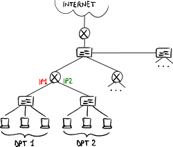 Backbone with IP segmentation.


Where is it better to position routers in a corporate network?
- access: only bridges (typically multilayer switches) connected directly to hosts;
- backbone: two possible solutions exist:
- VLAN segmentation: the whole corporate network is at the data-link layer, and every area (e.g. university department) is assigned a VLAN → mobility is extended to the whole corporate network;
- IP segmentation: each access bridge is connected to a router (typically layer 3 switch), and every area is assigned an IP network → higher network isolation and higher scalability.
Often internal bridges connect all the access routers one to each other and to the exit gateway router;
- edge: a router as the exit gateway toward Internet, usually an L4-7 multilayer switch having features at the transport layer and higher, such as protection (e.g. firewall), quality of service, load balancing, etc.
Example of LAN design
[edit | edit source]
- multilayer switch on the edge:
- with simple routers there would be a different IP network for each floor, to the benefit of mobility between floors;
- as many virtual interfaces are configured on the internal router as VLANs are in the building;
- all the ports towards floor bridges are configured in trunk mode, then every port can accept any VLAN, to the benefit of mobility between floors;
- it is an L4-7 multilayer switch for upper-layer features (in particular security functions);
- traffic between edge routers: an additional VLAN is specifically dedicated to L3 traffic which routers exchange (e.g. OSPF messages, HSRP messages), to split it from normal LAN traffic (otherwise a host may pretend to be a router and sniff traffic between routers);
- Multi-group HSRP (mHSRP): a multilayer switch can be active for some VLANs and stand-by for other ones;
- Per-VLAN Spanning Tree (PVST): a spanning tree protocol instance is active for each VLAN, to optimize paths based on VLANs.
The root bridge must always be the HSRP active router, otherwise some paths are not optimized; - direct link between multilayer switches:
- it provides a direct path for additional L3 traffic between routers;
- it lightens traffic load on floor bridges, which typically are dimensioned to support few traffic;
- ports at the endpoints of the link are configured as L2 ports, to give the possibility even to normal traffic to cross this link in case one of the link to floor bridges fails;
- it is doubled in link aggregation for a greater fault tolerance and to exploit the available bandwidth on both the links (avoiding STP disables one of the two links).