
Local Area Network design/Spanning Tree Protocol
The loop problem
[edit | edit source]
If the network has a logical ring in topology, some frames may start moving indefinitely in a chain multiplication around the loop:
- broadcast/multicast frames: they are always propagated on all ports, causing a broadcast storm;
- unicast frames sent to a station yet not included in the filtering database or inexistent: they are sent in flooding.
Moreover, bridges in the loop may have their filtering databases inconsistent, that is the entry in the filtering database related to the sender station changes its port every time a frame replication arrives through a different port, making the bridge believe that the frame has come from the station itself moving.
Spanning tree algorithm
[edit | edit source]| This page includes CC BY-SA contents from Wikipedia: Spanning Tree Protocol. |
The spanning tree algorithm allows to remove logical rings from the network physical topology, by disabling links[1] to transform a mesh topology (graph) into a tree called spanning tree, whose root is one of the bridges called root bridge.
Each link is characterized by a cost based on the link speed: given a root bridge, multiple spanning trees can be built connecting all bridges one with each other, but the spanning tree algorithm chooses the spanning tree made up of the lowest cost edges.
- Parameters
- Bridge Identifier: it identifies the bridge uniquely and includes:
- bridge priority: it can be set freely (default value = 32768);
- bridge MAC address: it is chosen between the MAC address of his ports by a vendor-specific algorithm and can not be changed;
- Port Identifier: it identifies the bridge port and includes:
- port priority: it can be set freely (default value = 128);
- port number: in theory a bridge can not have more than 256 ports → in practice also the port priority field can be used if needed;
- Root Path Cost: it is equal to the sum of the costs of all links, selected by the spanning tree algorithm, traversed to reach the root bridge (the cost for traversing a bridge is null).
Criteria
[edit | edit source]The spanning tree can be determined by the following criteria.
Root bridge
[edit | edit source]A root bridge is the root for the spanning tree: all the frames going from one of its sub-trees to another one must cross the root bridge.[2]
The bridge with the smallest Bridge Identifier is selected as the root bridge: the root of the spanning tree will be therefore the bridge with the lowest priority, or if there is a tie the one with the lowest MAC address.
Root port
[edit | edit source]- Criteria for selecting a root port for the bridge the arrow points to.
-
 Least-cost path.
 -
 Smallest remote Bridge ID.
 -
 Smallest remote Port ID.
 -
 Smallest local Port ID.


A root port is the port in charge of connecting to the root bridge: it sends frames toward the root bridge and receives frames from the root bridge.
- The cost of each possible path is determined from the bridge to the root. From these, the one with the smallest cost (a least-cost path) is picked. The port connecting to that path is then the root port for the bridge.
- When multiple paths from a bridge are least-cost paths toward the root, the bridge uses the neighbor bridge with the smallest Bridge Identifier to forward frames to the root. The root port is thus the one connecting to the bridge with the lowest Bridge Identifier.
- When two bridges are connected by multiple cables, multiple ports on a single bridge are candidates for root port. In this case, the path which passes through the port on the neighbor bridge that has the smallest Port Identifier is used.
- In a particular configuration with a hub where the remote Port Identifiers are equal, the path which passes through the port on the bridge itself that has the smallest Port Identifier is used.
Designated port
[edit | edit source]- Criteria for selecting a designated port for the link the arrow points to.
-
 Least-cost path.
 -
 Smallest local Bridge ID.
 -
 Smallest local Port ID.


A designated port is the port in charge of serving the link: it sends frames to the leaves and receives frames from the leaves.
- The cost of each possible path is determined from each bridge connected to the link to the root. From these, the one with the smallest cost (a least-cost path) is picked. The port connected to the link of the bridge which leads to that path is then the designated port for the link.
- When multiple bridges on a link lead to a least-cost path to the root, the link uses the bridge with the smallest Bridge Identifier to forward frames to the root. The port connecting that bridge to the link is the designated port for the link.
- When a bridge is connected to a link with multiple cables, multiple ports on a single bridge are candidates for designated port. In this case, the path which passes through the port on the bridge itself that has the smallest Port Identifier is used.
Blocked port
[edit | edit source]A blocked port never sends frames on its link and discards all the received frames (except for BPDU configuration messages).
Any active port that is not a root port or a designated port is a blocked port.

BPDU messages
[edit | edit source]The above criteria describe one way of determining what spanning tree will be computed by the algorithm, but the rules as written require knowledge of the entire network. The bridges have to determine the root bridge and compute the port roles (root, designated, or blocked) with only the information that they have.
Since bridges can exchange information about Bridge Identifiers and Root Path Costs, Spanning Tree Protocol (STP), standardized as IEEE 802.1D (1990), defines messages called BPDUs.
BPDU format
[edit | edit source]BPDUs have the following format:
| 1 | 7 | 8 | 16 | 24 | 32 |
| Protocol ID (0) | Version (0) | BPDU Type (0) | |||
| TC | 000000 | TCA | Root Priority | ||
| Root MAC Address | |||||
| Root Path Cost | |||||
| Bridge Priority | |||||
| Bridge MAC Address | |||||
| Port Priority | Port Number | Message Age | |||
| Max Age | Hello Time | ||||
| Forward Delay | |||||
| 16 | 24 | 32 |
| Protocol ID (0) | Version (0) | BPDU Type (0x80) |
where the fields are:
- Protocol Identifier field (2 bytes): it specifies the IEEE 802.1D protocol (value 0);
- Version field (1 byte): it distinguishes Spanning Tree Protocol (value 0) from Rapid Spanning Tree Protocol (value 2);
- BPDU Type field (1 byte): it specifies the type of BPDU:
- Configuration BPDU (CBPDU) (value 0): used for spanning tree computation, that is to determine the root bridge and the port states:
 #Ingress of a new bridge;
 - Topology Change Notification BPDU (TCN BPDU) (value 0x80): used to announce changes in the network topology in order to update entries in filtering databases: #Announcing topology changes;
- Configuration BPDU (CBPDU) (value 0): used for spanning tree computation, that is to determine the root bridge and the port states:
- Topology Change (TC) flag (1 bit): set by the root bridge to inform all bridges that a change occurred in the network;
- Topology Change Acknowledgement (TCA) flag (1 bit): set by the root bridge to inform the bridge which detected the change that its Topology Change Notification BPDU has been received;
- Root Identifier field (8 bytes): it specifies the Bridge Identifier of the root bridge in the network:
- Root Priority field (2 bytes): it includes the priority of the root bridge;
- Root MAC Address field (6 bytes): it includes the MAC address of the root bridge;
- Bridge Identifier field (8 bytes): it specifies the Bridge Identifier of the bridge which is propagating the Configuration BPDU:
- Bridge Priority field (2 bytes): it includes the priority of the bridge;
- Bridge MAC Address field (6 bytes): it includes the MAC address of the bridge;
- Root Path Cost field (4 bytes): it includes the path cost to reach the root bridge, as seen by the bridge which is propagating the Configuration BPDU;
- Port Identifier field (2 bytes): it specifies the Port Identifier of the port which the bridge is propagating the Configuration BPDU on:
- Port Priority field (1 byte): it includes the port priority;
- Port Number field (1 byte): it includes the port number;
- Message Age field (2 bytes): value, initialized to 0, which whenever the Configuration BPDU crosses a bridge is increased by the transit time throughout the bridge;[3]
- Max Age field (2 bytes, default value = 20 s): if the Message Age reaches the Max Age value, the received Configuration BPDU is no longer valid;[3]
- Hello Time field (2 bytes, default value = 2 s): it specifies how often the root bridge generates the Configuration BPDU;[3]
- Forward Delay field (2 bytes, default value = 15 s): it specifies the waiting time before forcing a port transition to another state.[3]
BPDU generation and propagation
[edit | edit source]Only the root bridge can generate Configuration BPDUs: all the other bridges simply propagate received Configuration BPDUs on all their designated ports. Root ports are the ones that receive the best Configuration BPDUs, that is with the lowest Message Age value = lowest Root Path Cost. Blocked ports never send Configuration BPDUs but keep listening to incoming Configuration BPDUs.
Instead Topology Change Notification BPDUs can be generated by any non-root bridge, and they are always propagated on root ports.
When a bridge generates/propagates a BPDU frame, it uses the unique MAC address of the port itself as a source address, and the STP multicast address 01:80:C2:00:00:00 as a destination address:
| 6 bytes | 6 bytes | 2 bytes | 1 byte | 1 byte | 1 byte | 4 bytes | |
| 01:80:C2:00:00:00 (multicast) | source bridge address (unicast) | ... | 0x42 | 0x42 | 0x03 | BPDU | ... |
| destination MAC address | source MAC address | length | DSAP | SSAP | CTRL | payload | FCS |
Dynamic behavior
[edit | edit source]Port states
[edit | edit source]- Disabled
- A port switched off because no links are connected to the port.
- Blocking
- A port that would cause a loop if it were active. No frames are sent or received over a port in blocking state (Configuration BPDUs are still received in blocking state), but it may go into forwarding state if the other links in use fail and the spanning tree algorithm determines the port may transition to the forwarding state.
- Listening
- The bridge processes Configuration BPDUs and awaits possible new information that would cause the port to return to the blocking state. It does not populate the filtering database and it does not forward frames.
- Learning
- While the port does not yet forward frames, the bridge learns source addresses from frames received and adds them to the filtering database. It populates the filtering database, but does not forward frames.
- Forwarding
- A port receiving and sending data. STP still keeps monitoring incoming Configuration BPDUs, so the port may return to the blocking state to prevent a loop.
| port state | port role | receive frames? | receive and process CBPDUs? | generate or propagate CBPDUs? | update filtering database? | forward frames? | generate or propagate TCN BPDUs? |
|---|---|---|---|---|---|---|---|
| disabled | blocked | no | no | no | no | no | no |
| blocking | yes | yes | no | no | no | no | |
| listening | (on transitioning) | yes | yes | yes | no | no | no |
| learning | designated | yes | yes | yes | yes | no | no |
| root | yes | yes | no | yes | no | sì | |
| forwarding | designated | yes | yes | yes | yes | yes | no |
| root | yes | yes | no | yes | yes | yes |
Ingress of a new bridge
[edit | edit source]When a new bridge is connected to a data-link network, assuming it has a Bridge Identifier highest than the one of the current root bridge in the network:
- at first the bridge, without knowing anything about the rest of the network (yet), assumes to be the root bridge: it set all its ports as designated (listening state) and starts generating Configuration BPDUs on them, saying it is the root bridge;
- the other bridges receive Configuration BPDUs generated by the new bridge and compare the Bridge Identifier of the new bridge with the one of the current root bridge in the network, then they discard them;
- periodically the root bridge in the network generates Configuration BPDUs, which the other bridges receive from their root ports and propagate through their designated ports;
- when the new bridge receives a Configuration BPDU from the root bridge in the network, it learns it is not the root bridge because another bridge having a Bridge Identifier lower than its one exists, then it stops generating Configuration BPDUs and sets the port from which it received the Configuration BPDU from the root bridge as a root port;
- also the new bridge starts propagating Configuration BPDUs, this time related to the root bridge in the network, on all its other (designated) ports, while it keeps receiving Configuration BPDUs propagated by the other bridges;
- when a new bridge receives on a designed port a Configuration BPDU 'best', based on criteria for designated port selection, with respect to the Configuration BPDU it is propagating on that port, the latter stops propagating Configuration BPDUs and turns to blocked (blocking state);
- after a time Forward Delay long, ports still designated and the root port switch from the listening state to the learning one: the bridge starts populating its filtering database, to avoid the bridge immediately starts sending the frames in flooding overloading the network;
- after a time Forward Delay long, designated ports and the root port switch from the learning state to the forwarding one: the bridge can propagate also normal frames on those ports.
Changes in the network topology
[edit | edit source]Recomputing spanning tree
[edit | edit source]When a topology change occurs, STP is able to detect the topology change, thanks to the periodic generation of Configuration BPDUs by the root bridge, and to keep guaranteeing there are no rings in topology, by recomputing if needed the spanning tree, namely the root bridge and the port states.
Link fault
[edit | edit source]When a link (belonging to the current spanning tree) faults:
- Configuration BPDUs which the root bridge is generating can not reach the other network portion anymore: in particular, the designed port for the faulted link does not send Configuration BPDUs anymore;
- the last Configuration BPDU listened to by the blocked port beyond the link 'ages' within the bridge itself, that is its Message Age is increased over time;
- when the Message Age reaches the Max Age value, the last Configuration BPDU listened to expires and the bridge starts over again electing itself as the root bridge: it resets all its ports as designated, and starts generating Configuration BPDUs saying it is the root bridge;
- STP continues analogously to the case previously discussed related to the ingress of a new bridge:
- if a link not belonging to the spanning tree connecting the two network portions exists, the blocked port connected to that link at last will become root port in forwarding state, and the link will join the spanning tree;
- otherwise, if the two network portions can not be connected one with each other anymore, in every network portion a root bridge will be elected.
Insertion of a new link
[edit | edit source]When a new link is inserted, the ports which the new link is connected to become designated in listening state, and start propagating Configuration BPDUs generated by the root bridge in the network → new Configuration BPDUs arrive through the new link:
- if the link has a cost low enough, the bridge connected to the link starts receiving from a non-root port Configuration BPDUs having a Root Path Cost lower than the one from the Configuration BPDUs received from the root port → the root port is updated so that the root bridge can be reached through the best path (based on criteria for root port selection), as well as designated and blocked ports are possibly updated accordingly;
- if the link has a too high cost, Configuration BPDUs crossing it have a too high Root Path Cost → one of the two ports connected to the new link becomes blocked and the other one keeps being designated (based on criteria for designated port selection).
Announcing topology changes
[edit | edit source]When after a topology change STP alters the spanning tree by changing the port states, it does not change entries in filtering databases of bridges to reflect the changes → entries may be out of date: for example, the frames towards a certain destination may keep being sent on a port turned to blocked, until the entry related to that destination expires because its ageing time goes to 0 (in the worst case: 5 minutes!).
STP contemplates a mechanism to speed up the convergence of the network with respect to the filtering database when a topology change is detected:
- the bridge which detected the topology change generates a Topology Change Notification BPDU through its root port towards the root bridge to announce the topology change;[4]
- crossed bridges immediately forward the Topology Change Notification BPDU through their root ports;
- the root bridge generates back a Configuration BPDU with Topology Change and Topology Change Acknowledgement flags set to 1, which after being forwarded back by crossed bridges will be received by the bridge which detected the topology change;[5]
- the root bridge generates on all its designated ports a Configuration BPDU with the Topology Change flag set;
- every bridge, when receiving the Configuration BPDU:
- drops all the entries in its filtering database having ageing times lower than the Forward Delay;
- in turn propagates the Configuration BPDU on all its designated ports (keeping the Topology Change flag set);
- the network temporarily works in a sub-optimal condition because more frames are sent in flooding, until bridges populate again their filtering databases with new paths by learning algorithms.
Issues
[edit | edit source]Performance
[edit | edit source]The STP philosophy is 'deny always, allow only when sure': when a topology change occurs, frames are not forwarded until it is sure that the transient has dead out, that is there are no loops and the network is in a coherent status, also introducing long waiting times at the expense of convergence speed and capability of reaching some stations.
Assuming to follow the timers recommended by the standard, namely:
- the timing values recommended by the standard are adopted: Max Age = 20 s, Hello Time = 2 s, Forward Delay = 15 s;
- the transit time through every bridge by a BPDU does not exceed the TransitDelay = HelloTime ÷ 2 = 1 s;
more than 7 bridges in a cascade between two end-systems can not be connected so that a Configuration BPDU can cross the entire network twice within the Forward Delay: if an eighth bridge was put in a cascade, in fact, in the worst case the ports at the new bridge, self-elected as the root bridge, would turn from the listening state to the forwarding one[6] before the Configuration BPDU coming from the root bridge at the other end of the network can arrive in time at the new bridge:[7]

With the introduction of the learning state, after a link fault the network takes approximately 50 seconds to converge to a coherent state:
- 20 s (Max Age): required for the last Configuration BPDU listened to to expire and for the fault to be detected;
- 15 s (Forward Delay): required for the port transition from the listening state to the learning one;
- 15 s (Forward Delay): required for the port transition from the learning state to the forwarding one.
In addition, achieving a coherent state within the network does not result necessarily in ending the disservice experienced by the user: in fact the fault may reflect also at the application layer, very sensitive to connectivity losses beyond a certain threshold:
- database management systems may start long fault-recovery procedures;
- multimedia networking applications generating inelastic traffic (such as VoIP applications) suffer much from delay variations.
It would be possible to try customizing the values related to timing parameters to increase the convergence speed and extend the maximum bridge diameter, but this operation is not recommended:
- without paying attention one risks reducing network reactivity to topology changes and impairing network functionality;
- at first sight it appears enough to work just on the root bridge because those values are all propagated by the root bridge to the whole network, but indeed if the root bridge changes the new root bridge must advertise the same values → those parameters must actually be updated on all bridges.
Often STP is disabled on edge ports, that is the ports connected directly to the end hosts, to relieve disservices experienced by the user:
- due to port transition delays, a PC connecting to the network would initially be isolated for a time two Forward Delays long;
- connecting a PC represents a topology change → the cleanup of old entries triggered by the announcement of the topology change would considerably increase the number of frames sent in flooding in the network.
However exclusively hosts must be connected to edge ports, otherwise loops in the network could be created → some vendors do not allow this: for example, Cisco's proprietary mechanism PortFast achieves the same objective without disabling STP on edge ports, being able to make them turn immediately to the forwarding state and to detect possible loops on them (that is two edge ports connected one to each other through a direct wire).
Scalability
[edit | edit source]Given a root bridge, multiple spanning trees can be built connecting all bridges one with each other, but the spanning tree algorithm chooses the spanning tree made up of the lowest cost edges. In this way, paths are optimized only with respect to the root of the tree:
- disabled links are altogether unused, but someone still has to pay for keeping them active as secondary links for fault tolerance;
- load balancing is not possible to distribute traffic over multiple parallel links → links belonging to the selected spanning tree have to sustain also the load for the traffic which, if there was not STP, would take a shorter path by crossing disabled links:

An IP network instead is able to organize traffic better: the spanning tree is not unique in the entire network, but every source can compute its own tree and send traffic to the shortest path guaranteeing a higher link load balancing.
Virtual LANs (VLAN) solve this problem by setting up multiple spanning trees.
Unidirectional links
[edit | edit source]STP assumes every link is bidirectional: if a link faults, frames can not be sent in either of two directions. Indeed fiber optical cables are unidirectional → to connect two nodes two optical fiber cables are needed, one for communication in one direction and another for communication in the opposite direction, and a fault on one of the two cables stops only traffic in one direction.
If one of the two unidirectional links faults, a loop may arise on the other link despite STP: Configuration BPDUs are propagated unidirectionally from the root to the leaves → if the direct propagation path breaks, the bridge at the other endpoint stops receiving from that link Configuration BPDUs from the root bridge, then moves the root port to another link and, assuming there is no one on that link, sets the port as designated creating a loop:

Unidirectional Link Detection (UDLD) is a proprietary protocol of Cisco's able to detect whether there are faults on a unidirectional link thanks to a sort of 'ping', and to disable the port ('error disabled' state) instead of electing it as designated.
Positioning the root bridge
[edit | edit source]-
 Optimal configuration.
 -
 Configuration to be avoided.


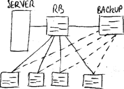
The location of the root bridge has heavy impact on the network:
- traffic from one side to another one of the network has to cross the root bridge → performance, in terms of aggregate throughput and bandwidth of ports, of the bridge selected as the root bridge should be enough to sustain a high amount of traffic;
- a star topology, where the root bridge is the star center, is to be preferred → every link connect only one bridge to the root bridge:
- more equable link load balancing: the link should not sustain traffic coming from other bridges;
- higher fault tolerance: a fault of the link affects only connectivity for one bridge;
- servers and datacenters should be placed near the root bridge in order to reduce the latency of data communication;
→ the priority needs to be customized to a very low value for the bridge which has to be the root bridge, so as not to risk that another bridge is elected as the root bridge.
The location of the backup bridge, meant to come into play in case of fault of a primary link or of the primary root bridge:
- fault of a primary link: the optimal configuration is a redundant star topology made up of secondary links, where every bridge is connected to the backup bridge by a secondary link;
- fault of the primary root bridge: the priority of the backup root bridge needs to be customized to a value slightly higher than the priority of the primary root bridge too, so as to force that bridge to be elected as the root bridge in case of fault.
Security
[edit | edit source]STP has not built-in security mechanisms against attacks from outside.
- Electing the user's bridge as the root bridge
A user may connect to the network a bridge with a very low priority forcing it to become the new root bridge and changing the spanning tree of the network. Cisco's proprietary feature BPDU Guard allows edge ports to propagate only Configuration BPDUs coming from inside the network, rejecting the ones received from outside (the port goes into 'error disabled' state).
- Rate limit on broadcast storm
Almost all professional bridges have some form of broadcast storm control able to limit the amount of broadcast traffic on ports by dropping excess traffic beyond a certain threshold, but these traffic meters can not distinguish between frames in a broadcast storm and broadcast frames sent by stations → they risk filtering legitimate broadcast traffic, and a broadcast storm is more difficult to be detected.
- Connecting bridges without STP
A single bridge without STP or with STP disabled can start pumping broadcast traffic into the network so that a loop outside the control of STP is created: connecting a bridge port directly to another one of the same bridge, or connecting the user's bridge to two internal bridge of the network through two redundant links, are examples.
- Multiple STP domains
Sometimes two different STP domains, each one with its own spanning tree, should be connected to the same shared channel (e.g. two providers with different STP domains in the same datacenter). Cisco's proprietary feature BPDU Filter disables sending and receiving Configuration BPDUs on ports at domain peripheries, to keep the spanning trees separated.
References
[edit | edit source]- ↑ Really the spanning tree algorithm blocks ports, not links: {{subst:vedi|#Port states}}
- ↑ Please pay attention to the fact that the traffic moving within the same sub-tree does not cross the root bridge.
- ↑ a b c d Time fields are expressed in units of 256th seconds (about 4 ms).
- ↑ The bridge keeps generating the Topology Change Notification BPDU every Hello Time, until it receives the acknowledge.
- ↑ The root bridge keeps generating back the acknowledgement Configuration BPDU for Max Age + Forward Delay.
- ↑ When this constraint was established, the learning state had not been introduced yet and the ports turned directly from the listening state to the forwarding one.
- ↑ Exactly the minimum value for the Forward Delay would be equal to 14 s, but a tolerance 1 s long was contemplated.