Klann linkage
About this Book
[edit | edit source]This wikibooks shall be a supplement to the Wikipedia article of the same name.
On Wikipedia, there is a need to compromise between readability, details and amount of illustration. It is impossible, to give an overview to the general public and an in depth view for engineers diving deeper into the topic at the same time.
So: Where the Wikipedia article brings a general overview, this book brings depth and details.
This book will also talk about the relevant patent(s). This book will shall not replace studying the patent, but simplifying it by providing additional tables and illustrations.
As the author of this book, I would like to cite larger sections of the patents. As the content of a patent may be copyrighted, this book will only cite small sections of the patent to be on the safe side.
A big thanks has to go to the patent holder Joseph Klann for his website,[1] which is a great reference and for uploading pictures[2] to Wikimedia Commons. Without the pictures from Joseph Klann on Commons and without his website, this book would not have been possible.
This book is the partner book to Comparison of crank based leg mechanism.
Parts
[edit | edit source]To get started, we look at the parts of the Klann Linkage, starting with a leg unit.
Leg Unit
[edit | edit source]First we take a look at this illustration:

In the patent, those parts are numbered as follow:
| Number | Name | |
|---|---|---|
| 3 | supportive Frame | |
| 5 | first rocker arm | |
| 7 | second rocker arm | |
| 6 | spacer | [3] |
| 13 | crank | |
| 21 | connecting rod | |
| 31 | leg |
The supportive frame is of course simplified.
The axes/joints are named:

| Number | Name | |
|---|---|---|
| 9 | first rocker arm axle | |
| 11 | second rocker arm axle | |
| 15 | crank shaft | |
| 27 | elbow joint | |
| 29 | crank | |
| 33 | foot | |
| 35 | knee joint/axle | |
| 37 | hip joint |
a pair of legs
[edit | edit source]Two leg units combine to form, as Mister Klann puts it,[4] a wheel replacement.
The two units are one-half cycle out of phase (= 180 degree) to each other.
a full device
[edit | edit source]A full device consists of at least three pairs of legs, which means a total of six legs.[5]

Practical implementations might use eight legs for stability.
-
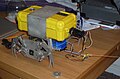 Lobsterbot - a robot with a total of eight legs
 -
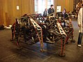 Mondospider - A robot with a total of eight legs


(see also https://web.archive.org/web/20170812223320/http://www.mechanicalspider.com/ [3] for designs using the Klann linkage)
Geometry
[edit | edit source]Now we take a look at the "Enable diagram of Klann linkage" from Mister Klann:

How to construct it is described in the patent and on the website of the patent holder.
Our concern at the moment is how to interpret this drawing.
Points ending with "x" belong to the fully extended leg.
Points ending with "y" belong to the grounded gait position.
Points ending without a letter are fix points.
Points ending with "p" are auxiliary points used to construct the other points.
The suffix "c" is used for circles, "s" for straight lines and "a" are angles.
By "connecting the dots" without suffix, "x" suffix and "y" suffix, we can derive a first meaning from the drawing, showing us the frame and the leg in two positions.
examples
[edit | edit source]In the patent, there is are two tables with coordinates. Here we use those tables, but with the point description written next to it.
Table 1
[edit | edit source]

| Point | X | Y | Description |
|---|---|---|---|
| Fixpoints | |||
| 9 | 1.366 | 1.366 | first rocker arm axle |
| 11 | 1.009 | 0.574 | second rocker arm axle |
| 15 | 1.599 | 0.750 | crank shaft |
| fully extended ground stride position | |||
| 27X | 0.741 | 0.750 | elbow joint |
| 29x | 1.331 | 0.750 | crank |
| 33x | 0.000 | 0.000 | foot |
| 35x | 0.232 | 0.866 | knee joint/axle |
| 37x | 0.866 | 1.500 | hip joint |
| grounded gait position | |||
| 27Y | 1.277 | 0.750 | elbow joint |
| 29y | 1.867 | 0.750 | crank |
| 33y | 1.000 | 0.000 | foot |
| 35y | 0.768 | 0.866 | knee joint/axle |
| 37y | 1.000 | 1.732 | hip joint |
| Auxiliary points | |||
| 52p | 0.500 | 0.866 | |
| 56p | 0.000 | 1.732 | |
| 57p | 1.000 | 1.732 | |
| 62p | 0.500 | 1.866 | |
| 65p | 0.500 | -0.134 | |
| 72p | 0.500 | 0.901 | |
| 74p | 0.500 | 0.844 | [6] |
| 75p | 1.599 | 0.844 | [7] |
| 78p | 1.599 | 1.018 | |
| 80p | 1.022 | 0.894 | |
| Table 1a | |||
(the table in the Wikipedia article is a cut down version of this table)
Table 2
[edit | edit source]

| Point | X | Y | Description |
|---|---|---|---|
| Fixpoints | |||
| 9 | 17.818 | 16.076 | first rocker arm axle |
| 11 | 12.101 | 10.186 | second rocker arm axle |
| 15 | 17.607 | 11.807 | crank shaft |
| fully extended ground stride position | |||
| 27X | 9.125 | 11.807 | elbow joint |
| 29X | 14.631 | 11.807 | crank |
| 33x | 0.000 | 0.000 | foot |
| 35x | 3.024 | 13.099 | knee joint/axle |
| 37x | 11.119 | 19.200 | hip joint |
| grounded gait position | |||
| 27Y | 15.077 | 11.807 | elbow joint |
| 29Y | 20.583 | 11.807 | crank |
| 33y | 12.000 | 0.000 | foot |
| 35y | 8.976 | 13.099 | knee joint/axle |
| 37y | 13.578 | 22.130 | hip joint |
| Auxiliary points | |||
| 52p | 6.000 | 13.992 | |
| 56p | 0.000 | 24.384 | |
| 57p | 12.000 | 24.384 | |
| 62p | 6.000 | 25.992 | |
| 65p | 6.000 | 1.992 | |
| 72p | 6.000 | 13.491 | |
| 74p | 6.000 | 13.925 | [8] |
| 75p | 17.607 | 13.925 | [9] |
| 78p | 17.607 | 14.783 | |
| 80p | 12.236 | 13.572 | |
| Table 2a | |||
(this table is omitted in the wikipedia article)
Input Variables
[edit | edit source]The geometric construction according to U.S. Patent 6,260,862 or more specifically the patent holders website[10] has six input variables. We will consider the stride length as an input as well (here input 0), as table 2 uses bigger stride length. (notice that the same effect can be achieved by scaling all points and lengths proportionally)
An other thing to keep in mind is, that not all combinations of inputs result in a working linkage.
Table 1
[edit | edit source]The input variables for figure 17 (and therefore table 1) according U.S. Patent 6,260,862 are as follow: the values on the patent holders website for figure 2[11] are identical, but rounded
| Input | Value | Reference | Description |
|---|---|---|---|
| Input 0 | 1.0000 units | length of line 50s (distance between 33x and 33y) | length of the stride |
| Input 1 | 0.8660 units | height of point 52p above line 50s | |
| Input 2 | 1.0000 units | Radius of circle 53c (circle 53c centred at 52p) | |
| Input 3 | 60 degree | ||
| Input 4 | -90 degree | Location of point 65p on circle above horizontal | |
| Input 5 | 1.0991 units | Distance from point 74p to point 75p | |
| Input 6 | 0.5895 units | distance of between points 29x and 27x | |
| Table 1b | |||
Notice that this set of values has some special properties:
- point 33x and 33y are both on circle 53c (which is not necessary as we see in table 2 from the patent)
- line 67s and 51n overlap (which is caused by the -90 degree angle as input 4)
Therefore: Do not over generalize the drawing.
(if your colour blind: sorry for the heavy colour coding, but given the complexity of the drawing, I could not avoid to colour code the drawing)
Table 2
[edit | edit source]The input values for table 2 aren´t given in the patent on or the patent holders website, but can be reconstructed from table 2.
| Input | Value | Reference | Description |
|---|---|---|---|
| Input 0 | 12.000 units | length of line 50s (distance between 33x and 33y) | length of the stride |
| Input 1 | 13.992 units | height of point 52p above line 50s | |
| Input 2 | 12.000 units | Radius of circle 53c (circle 53c centered at 52p) | |
| Input 3 | 80 degree | ||
| Input 4 | -90 degree | Location of point 65p on circle above horizontal | |
| Input 5 | 11.607 units | Distance from point 74p to point 75p | |
| Input 6 | 5.506 units | distance of between points 29x and 27x | |
| Table 2b | |||
Notice that this set of values has some special properties:
- line 67s and 51n overlap (which is caused by the -90 degree angle as input 4)
Therefore: Do not over generalize the drawing.
Inputs
[edit | edit source]In this drawing, you see how the input variables influence the linkage:

Foot
[edit | edit source]An important part for a complete robot is the foot.
Inspiration for the foot can be found in the patent, Mondo spider Design and Theo Jansens Strandbeest Design.
Detailed analysis - walking
[edit | edit source]Table 1
[edit | edit source]Presuming that the fasted foot defines the speed of the whole robot, we can animate a Robot based on the values in table 1:


It is a bit tricky to realize in the animation, but obvious in the graph: The robot comes to an almost stand still during each crank revolution.
Table 2
[edit | edit source]with the same assumption, we can also animate the robot according to table 2:

Further reading
[edit | edit source]References
[edit | edit source]- ↑ https://web.archive.org/web/20170812223320/http://www.mechanicalspider.com/ [1]
- ↑ https://commons.wikimedia.org/wiki/Special:Contributions/Jck56270
- ↑ not shown in the picture above
- ↑ https://web.archive.org/web/20170728172050/http://www.mechanicalspider.com/concept.html [2]
- ↑ https://www.google.com/patents/US6260862
- ↑ coordinate missing in the patent
- ↑ coordinate missing in the patent
- ↑ coordinate missing in the patent
- ↑ coordinate missing in the patent
- ↑ http://www.mechanicalspider.com/enable.html
- ↑ http://www.mechanicalspider.com/enable.html