Circuit Idea/Bistable Mode of Current Inversion NIC
Jump to navigation
Jump to search
<<< contents - bistable VNIC - linear INIC - linear VNIC - negative impedance - page stage >>>
Investigating the Bistable Mode of Negative Impedance Converters with Current Inversion

INIC operating in bistable mode is a current-driven N-shaped true negative resistor. 
Fig. 1a: A hysteresis IV curve of current-driven INIC. 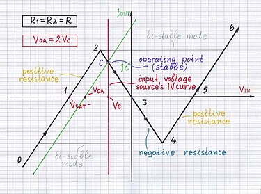
Fig. 1b: An N-shaped IV curve of voltage-driven INIC. 
Fig. 2a: Scanning the left bottom part (0 - 1) of the curve. 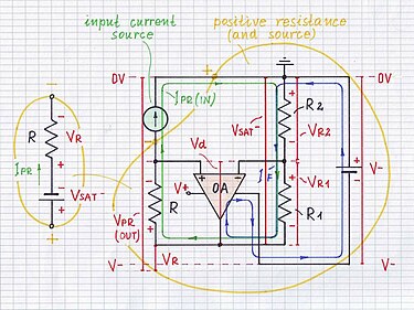
Fig. 2b: Sinking a current from INIC. 
Fig. 3a: Investigating the point 1 of the curve. 
Fig. 3b: Sinking no current from INIC. 
Fig. 4a: Scanning the left top part (1 - 2) of the curve. 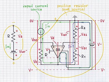
Fig. 4b: Injecting a current to INIC. 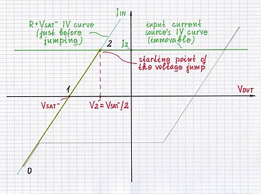
Fig. 5-1a: Investigating the starting point of the voltage jump. 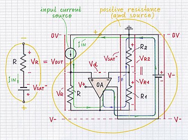
Fig. 5-1b: Making the op-amp "jump" to the positive rail. 
Fig. 5-2a: Scanning the top jumping path (2 - 3). 
Fig. 5-2b: The op-amp "jumps" to the positive rail. 
Fig. 5-3a: Investigating the final point of the voltage jump upward. 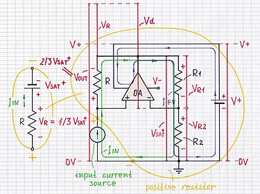
Fig. 5-3b: The op-amp "calms down" at the positive rail. 
Fig. 6a: Scanning the right top part (3 - 4) of the curve. 
Fig. 6b: Injecting a big current to INIC. 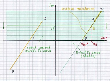
Fig. 7a: Scanning the right top part (4 - 5) of the curve. 
Fig. 7b: Injecting a current to INIC. 
Fig. 8a: Investigating the point 5 of the curve. 
Fig. 8b: Injecting no current to VNIC. 
Fig. 9a: Scanning the right bottom part (5 - 6) of the curve. 
Fig. 9b: Sinking a current from INIC. 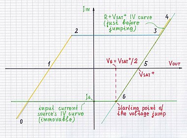
Fig. 10-1a: Investigating the starting point of the voltage jump. 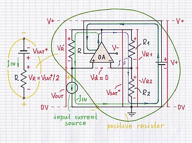
Fig. 10-1b: Making the op-amp "jump" to the negative rail. 
Fig. 10-2a: Scanning the bottom jumping path (6 - 7). 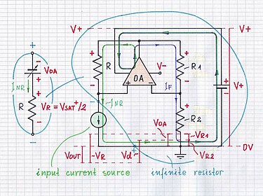
Fig. 10-2b: The op-amp "jumps" to the negative rail. 
Fig. 10-3a: Investigating the final point of the voltage jump downward. 
Fig. 10-3b: The op-amp "calms down" at the negative rail. 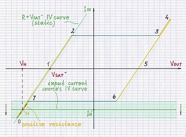
Fig. 11a: Scanning the left bottom part (7 - 0) of the curve. 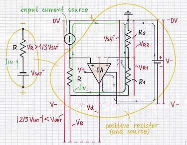
Fig. 11b: Siniking a big current from INIC.
<<< top - contents - bistable VNIC - linear INIC - linear VNIC - negative impedance - page stage >>>

Circuit idea: Making the positive feedback dominate over the negative one.

Introduction
[edit | edit source]What a current inversion NIC to operate in bistable mode means
[edit | edit source]How to investigate the bistable mode of current inversion NIC
[edit | edit source]

Investigating the circuit at ideal driving conditions
[edit | edit source]Increasing the input current
[edit | edit source]Negative input current, negative output voltage
[edit | edit source]

Zero input current, negative output voltage
[edit | edit source]

Positive input current, negative output voltage
[edit | edit source]

Voltage jump upward
[edit | edit source]...start...
[edit | edit source]

...middle...
[edit | edit source]

...final
[edit | edit source]

Positive input current, positive output voltage
[edit | edit source]

Decreasing the input current
[edit | edit source]Positive input current, positive output voltage
[edit | edit source]

Zero input current, positive output voltage
[edit | edit source]

Negative input current, positive output voltage
[edit | edit source]

Voltage jump downward
[edit | edit source]...start...
[edit | edit source]

...middle...
[edit | edit source]

...final
[edit | edit source]

Negative input current, negative output voltage
[edit | edit source]

Investigating the circuit at real driving conditions
[edit | edit source]How to make INIC operate in bistable mode
[edit | edit source]What is the relation with the non-inverting comparator with hysteresis?
[edit | edit source]See also
[edit | edit source]Revealing the mystery of negative impedance
Investigating the linear mode of negative impedance converters with current inversion
Negative impedance converter from Wikipedia considers NIC with current inversion (INIC).
References
[edit | edit source]