Wikijunior:How Things Are Made/Electrical Appliances/Radio
Products
[edit | edit source]-
 A radio
 -
 A disassembled radio with a loudspeaker attached to it
_Transistor_Radio,_Model_RF-800,_9_Transistors,_Made_In_Japan,_Circa_1965_(14633774476).jpg)

The radio receives electromagnetic waves from the air that are sent by a radio transmitter. Electromagnetic waves are a combination of electrical and magnetic fields that overlap. The radio converts these electromagnetic waves, called a signal, into sounds that humans can hear.
What do we need to make this thing?
[edit | edit source]Today's radio consists of an antenna, printed circuit board, resistors, capacitors, coils and transformers, transistors, integrated circuits, and a speaker. All of these parts are housed in a plastic case.
Antenna - Antenna usually consists of either internal or external type. An internal antenna consists of small-diameter insulated copper wire wound around a ferrite core. An external antenna consists of several aluminum tubes that slide within one another.
(PCB) Printed circuit board - The printed circuit board consists of a copper-clad pattern cemented to a phenolic board. The copper pattern is the wiring from component to component. It replaces most of the wiring used in earlier radios.
Resistors - The resistors consist of a carbon film deposited on a cylindrical substrate, encased in a plastic (alkyd polyester) housing, with wire leads made of copper.
Capacitors - Capacitors grouped into two types: Variable or fixed. Fixed capacitors consist of two extended aluminum foil electrodes insulated by polypropylene film, housed in a plastic or ceramic housing with copper wire leads. Variable capacitors have a set of fixed aluminum plates and a set of rotating aluminum plates with an air insulator.
Coils and transformers - They consist of two or more sets of copper wire coils either wound on an insulator or mounted side-by-side with air as the insulator.
Transistors - It consist of germanium or silicon encased in a metal housing with copper wire leads.
(IC) Integrated circuit - It houses thousands of resistors, capacitors, and transistors into a small and compact package called a chip. This chip is about the size of the nail on the little finger. The chip is mounted in a plastic case with aluminum tabs that allow it to be mounted to a printed circuit board.
What is the step by step process?
[edit | edit source]There is no single process for manufacturing a radio. The manufacturing process depends upon the design and complexity of the radio.
- Step 1: The blank printed circuit board consists of a glass epoxy resin with a thin copper film cemented to one or both sides. A light sensitive photoresist film is placed over the copper film. A mask containing the electrical circuitry is placed over the photoresist film. The photoresist film is exposed to ultraviolet light. The photoresist image is developed, transferring the image to the copper film. The unexposed areas dissolve during etching and produce a printed circuit on the board. This process is called chemical etching.
- Step 2: Holes are drilled in designated locations on the printed circuit board to accept the components. Then, the board is pre-soldered by dipping it in a bath of hot solder.
- Step 3: Smaller electronic components such as resistors, capacitors, transistors, integrated circuits, and coils are installed in their designated holes on the printed circuit board and soldered to the board. These operations can be performed by hand or by robots.
- Step 4: Larger components such as power transformer, speaker, and antenna are mounted either on the PCB or cabinet with screws or metal spring tabs.
- Step 5: The case that houses the radio can be made either of plastic or aluminum. Plastic cases are made from pellets that are melted and injected into a mold. Aluminum cases are stamped into shape from sheet aluminum by a metal press.
- Step 6: External components not mounted on the printed circuit board can be the antenna, speaker, power transformer, volume, and frequency controls are mounted in the case with either screws, rivets, or plastic snaps. The printed circuit board is then mounted in the case with screws or snaps. The external components are connected and soldered to the printed circuit board with insulated wires made of copper and plastic insulation.
-
 Step 1: Chemical etching for PCB board
 -
 Step 2: Holes are drilled on PCB
 -
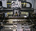 Step 3 : Electronics are placed onto PCB Assembly
 -
 Step 5: Aluminum case usually are made from metal press


