Practical Electronics/Operational amplifiers
Intro
[edit | edit source]Op Amp is a short hand term for Operational Amplifier. An operational amplifier is a circuit component that amplifies the difference of two input voltages:
- Vo = A (V2 - V1)
Op Amps are usually packaged as an 8-pin integrated circuit.

| Pin | Usage |
|---|---|
| 1 | Offset Null |
| 2 | Inverted Input |
| 3 | Non-Inverted Input |
| 4 | -V Supply |
| 5 | No use |
| 6 | Output |
| 7 | +V Supply |
| 8 | No use |
Op Amp symbol

- V+: non-inverting input
- V−: inverting input
- Vout: output
- VS+: positive power supply
- VS−: negative power supply
Op amps amplify AC signal or AC Voltage better than a simple bipolar junction transistor.
Op Amp Functions
[edit | edit source]Voltage Difference Amplifier
[edit | edit source]From above
- V0 = A (V2 - V1)
Voltage Comparator
[edit | edit source]- V2 > V1 , V0 = +Vss
- V2 < V1 , V0 = -Vss
- V2 = V1 , V0 = 0
Inverting Amplifier
[edit | edit source]With one voltage is grounded
- If V2 = 0 , V0 = -A V1 . Inverting Amplifier
Non-Inverting Amplifier
[edit | edit source]With one voltage is grounded
- If V1 = 0 , V0 = A V2 . Non-Inverting Amplifier
Linear Configurations
[edit | edit source]Differential amplifier
[edit | edit source]

- Differential (between the two input pins) =


Voltage Difference Amplifier
[edit | edit source]Whenever and ,


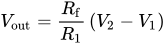
Voltage Difference
[edit | edit source]When and (including previous conditions, so that ):




Inverting Amplifier
[edit | edit source]
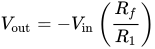
Inverting Amplification is dictated by the ratio of the two resistors
Non-Inverting Amplifier
[edit | edit source]
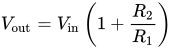
Non-Inverting Amplification is dictated by the ratio of the two resistors plus one
Voltage Follower
[edit | edit source]
From Non-Inverting Amplifier's formula. If the resistors has the same value of resistance then output voltage is exactly equal to the input voltage

From Inverting Amplifier's formula. If the resistors has the same value of resistance then output voltage is exactly equal to the input voltage and inverted

Summing amplifier
[edit | edit source]

When , and independent



When


Integrator
[edit | edit source]
Integrates the (inverted) signal over time
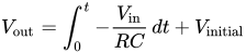
(where and are functions of time, is the output voltage of the integrator at time t = 0.)


Differentiator
[edit | edit source]
Differentiates the (inverted) signal over time.
The name "differentiator" should not be confused with the "differential amplifier", also shown on this page.
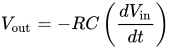
(where and are functions of time)
Comparator
[edit | edit source]
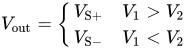
Từ V0 = A (V2 - V1)
- Vo = 0 khi V2 = V1
- Vo > 0 khi V2 > V1
- Vo = Vss
- Vo < 0 khi V2 < V1
- Vo = V-ss
When two input voltages equal. The output voltage is zero . When the two input voltages different and if one is greater than or less than the other
- Vo = Vss khi V2 > V1
- Vo = V-ss khi V2 < V1
Instrumentation amplifier
[edit | edit source]
Combines very high input impedance, high common-mode rejection, low DC offset, and other properties used in making very accurate, low-noise measurements
- Is made by adding a inverting buffer to each input of the differential amplifier to increase the input impedance.
Schmitt trigger
[edit | edit source]
A comparator with hysteresis
Hysteresis from to .


Gyrator
[edit | edit source]
A gyrator can transform impedances. Here a capacitor is changed into an inductor.

Zero level detector
[edit | edit source]Voltage divider reference
- Zener sets reference voltage
Negative impedance converter (NIC)
[edit | edit source]
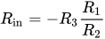
Creates a resistor having a negative value for any signal generator
- In this case, the ratio between the input voltage and the input current (thus the input resistance) is given by:
Non-linear configurations
[edit | edit source]Rectifier
[edit | edit source]
Behaves like an ideal diode for the load, which is here represented by a generic resistor .

- This basic configuration has some limitations. For more information and to know the configuration that is actually used, see the main article.
Peak detector
[edit | edit source]
When the switch is closed, the output goes to zero volts. When the switch is opened for a certain time interval, the capacitor will charge to the maximum input voltage attained during that time interval.
The charging time of the capacitor must be much shorter than the period of the highest appreciable frequency component of the input voltage.
Logarithmic output
[edit | edit source]
- The relationship between the input voltage and the output voltage is given by:


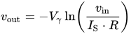
where is the saturation current.

- If the operational amplifier is considered ideal, the negative pin is virtually grounded, so the current flowing into the resistor from the source (and thus through the diode to the output, since the op-amp inputs draw no current) is:
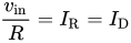
where is the current through the diode. As known, the relationship between the current and the voltage for a diode is:

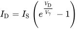
This, when the voltage is greater than zero, can be approximated by:

Putting these two formulae together and considering that the output voltage is the inverse of the voltage across the diode , the relationship is proven.

Note that this implementation does not consider temperature stability and other non-ideal effects.
Exponential output
[edit | edit source]
- The relationship between the input voltage and the output voltage is given by:
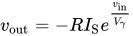
where is the saturation current.
- Considering the operational amplifier ideal, then the negative pin is virtually grounded, so the current through the diode is given by:
when the voltage is greater than zero, it can be approximated by:
The output voltage is given by:
