Practical Electronics/Finding component information/Resistors
Identifying resistors
[edit | edit source]Most axial resistors use a pattern of colored stripes to indicate resistance. Meanwhile, SMD resistors follow a numerical pattern.
-
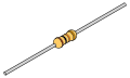 A through-hole mounted (axial) resistor with untrimmed leads. This is a 10kΩ, 5% tolerance resistor.
 -
 SMD resistor which the 3 digit code represents 56kΩ


Resistor colour code
[edit | edit source]Resistors are labelled to allow you to see what their nominal value is. A "standard" through-hole mounted resistor has coloured bands painted onto it. These bands denote the value. Depending on the tolerance of the resistor, these my be 4, 5, or 6 bands on a resistor.
4 - digits resistor code table
[edit | edit source]4 band identification is the most commonly used color coding scheme on all resistors. It consists of four colored bands that are painted around the body of the resistor. The scheme is simple: The first two numbers are the first two significant digits of the resistance value, the third is a multiplier, and the fourth is the tolerance of the value. Each color corresponds to a certain number, shown in the chart below. The tolerance for a 4-band resistor will be 2%, 5%, or 10%

| Colour | Significant figures |
Multiplier | Tolerance | Temp. Coefficient (ppm/K) | ||
|---|---|---|---|---|---|---|
| Black | – | ×100 | – | 250 | U | |
| Brown | 1 | ×101 | ±1% | F | 100 | S |
| Red | 2 | ×102 | ±2% | G | 50 | R |
| Orange | 3 | ×103 | – | 15 | P | |
| Yellow | 4 | ×104 | – | 25 | Q | |
| Green | 5 | ×105 | ±0.5% | D | 20 | Z |
| Blue | 6 | ×106 | ±0.25% | C | 10 | Z |
| Violet | 7 | ×107 | ±0.1% | B | 5 | M |
| Gray | 8 | ×108 | ±0.05% | A | 1 | K |
| White | 9 | ×109 | – | – | ||
| Gold | – | ×10−1 | ±5% | J | – | |
| Silver | – | ×10−2 | ±10% | K | – | |
| None | – | – | ±20% | M | – | |
| ||||||
5 / 6 - digits resistor code table
[edit | edit source]For 5-band identification is used for higher tolerance resistors (1%, 0.5%, 0.25%, 0.1%), to notate the extra digit. The first three bands represent the significant digits, the fourth is the multiplier, and the fifth is the tolerance.
For 6-band identification is used in case of high precision resistors, there is an extra band to indicate the temperature coefficient. The first 5 bands are same as five band resistors.
The most common color used for sixth band is black which represents 100ppm/K. This indicates that for a change of 100C in temperature, there can be a change of 0.1% in the value of resistance. Generally the sixth band represents temperature coefficient. But in some cases it may represent reliability and failure rate.

Color 1st band 2nd band 3rd band Multiplier Tolerance Temp. Coefficient Black 0 0 0 ×100 Brown 1 1 1 ×101 ±1% (F) 100 ppm Red 2 2 2 ×10² ±2% (G) 50 ppm Orange 3 3 3 ×10³ 15 ppm Yellow 4 4 4 ×10⁴ 25 ppm Green 5 5 5 ×10⁵ ±0.5% (D) Blue 6 6 6 ×10⁶ ±0.25% (C) Violet 7 7 7 ×10⁷ ±0.1% (B) Gray 8 8 8 ×10⁸ ±0.05% (A) White 9 9 9 ×10⁹ Gold ×0.1 (10−1) ±5% (J) Silver ×0.01 (10−2) ±10% (K) None ±20% (M)
There are some mnemonics to remember the sequence of color code in the above table. A few of them are as follows:
- Bad Boys Race Our Young Girls, But Violet Generally Wins.
- Better Be Ready, Or Your Great Big Venture Goes West.
- B. B. ROY of Great Britain has a Very Good Wife.
Number codes
[edit | edit source]Surface mount resistors are too small for coloured bands to be easily read, but they have a flat surface instead, so the value is usually marked un the top surface of the device. This code is much the same as the colour code above, but explicitly written.
There are 3 types of number codes for resistor
(a) 3 digit codes
(b) 4 digit codes and;
(c) EIA 96 codes
So, the code is written as two or three (depending on the tolerance of the device) numbers, followed by a multiplier digit, giving a three- or four-digit designation.

3 digit codes
[edit | edit source]In three digit coding, the first two numbers indicate the significant value of the resistance and the third number indicates the multiplier like 10 in case the digit is 1, 100 in case the digit is 2 or 1000 in case the digit is 3 and so on.
For example as seen on the picture on the right there are SMD resistors labelled 270 and 0 :
- The label 270 can be read as 27 * 100 = 27*1 = 27Ω
- The label 0 can be read as 0Ω (It is also known as "jumper resistor" and are used to bypass tracks on a PCB.

See the picture on the left .If the resistance value is less than 10Ω, the numbering will include letter R to denote decimal placing.
- The label 4R7 can be read as 4.7Ω
- The label 101 can be read as 10*101=10Ω
- The label 100 can be read as 10*100=1Ω

4 digit codes
[edit | edit source]For 4 decimal points , a four digit code is marked on them.
The calculation is similar to three digit code. The first three numbers indicate the significant value of the resistance and the fourth number indicates the multiplier.
- The label 2211 can be read as 221*101= 221Ω
- The label 1002 can be read as 100*102=10,000Ω
EIA 96 codes
[edit | edit source]

The EIA 96 code usually have 3 digits , first two are to indicate the three significant digits of the value of resistance (See table EIA 96 Resistor Marking Code) and third alphabet is to indicate multiplier (See table EIA 96 Multiplier Marking Code)
As example, the picture below shows a resistor of marking 85A which is read as
- 85 = 750Ω (See table EIA 96 Resistor Marking Code)
- A = 1 (See table EIA 96 Multiplier Marking Code)
750Ω*1 = 750Ω
Another example is marking 01C which is read as
- 01 = 100Ω (See table EIA 96 Resistor Marking Code)
- C = 100 (See table EIA 96 Multiplier Marking Code)
100Ω *100 = 10,000Ω

