OpenSCAD User Manual/Example/Strandbeest
Abstract
[edit | edit source]
This chapter describes how to animate a complex mechanism like the strandbeest using OpenSCAD.
The model is not meant for 3D-Printing.
The source code is just one file without the use of external libraries, tested with OpenSCAD version 2015.03.
Target audience / Prerequisites
[edit | edit source]You need to have OpenSCAD installed and need to have a basic understanding in how to use OpenSCAD.
A basic understanding of geometry is necessary to understand on how to construct the linkage on paper and how to use the functions which are used to calculate the linkage. An understanding of trigonometry is helpful to understand the math behind the functions, but it is not strictly necessary.
Preparation
[edit | edit source]First of all, we need a drawing with the constants.
Theo Jansen has published the numbers on his website: [1] (Video "The Legsystem", 3:36) or on archived version the webpage: [2]

I suggest to name the points. The naming can be arbitrary. I have used Z..S to avoid confusion with the lengths a..m.

It can be very helpful to print out the drawing to scribble on.
Construction by hand
[edit | edit source]Now we have to think about how we could construct the mechanism by hand.
We need a non collapsible compass, a ruler, paper and a pencil.
-
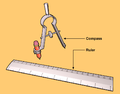 non collapsible compass and ruler

We set the origin Z to an arbitrary point. For Y, we are going down l and a to the left. The crank m can be at an arbitrary angle. Drawing the crank results in the point X.
From this point, we construct triangles that are defined by two points and two lengths.
In geometry, this is the SSS case (constructing a Triangle with three sides given, see also Solution of triangles#Three sides given (SSS)).
On paper, this can be easily solved using a compass.
Let us start with setting the compass to length b and then putting the compass in point Y. Then we set the compass to the length j and put the compass in point X. The crossing point of the arcs is the point W.
Note that when two points and two lengths are given, there are always two solutions, speak crossing points. Given that we already know the general shape of the mechanism, we know which one we need. But keep it mind for later.
The rest is more or less "rinse and repeat".
Geometric Construction Instructions
[edit | edit source]Conventions
[edit | edit source]- lengths are written in lower case
- point are written in upper case
- lines and arcs used for construction have a '
Instructions
[edit | edit source]- construct point Z
- draw a horizontal line h
- draw a vertical line v crossing the horizontal line h
- mark point Z where the h and v cross
- that will be the origin of this construction and crank axis of the leg mechanism
- construct point Y
- draw a horizontal line h' distance l down from h
- draw a vertical line v' distance a left from v
- label the crossing point of h' and v' as fix point Y
- construct point X
- draw a line m' trough Z add an arbitrary angle (the angle is the crank angle)
- draw an arc from point Z with radius m, the crossing point of arc n and Point Z is crank pivot X
- draw line m from Z to X
- construct point W (SSS case)
- draw an arc j' from point X with radius j
- draw an arc b' from point Y with radius b
- the crossing point of arc j' and b' is point W
- draw line j from X to W
- draw line b from Y to W
- construct point V (SSS case)
- draw an arc e' from point W with radius e
- draw an arc d' from point Y with radius d
- draw line e from W to V
- draw line d from Y to V
- the crossing point of arc e' and d' is point V
- construct point U (SSS case)
- draw an arc c' from point Y with radius c
- draw an arc k' from point X with radius k
- draw line c from Y to U
- draw line k from X to U
- the crossing point of arc c' and k' is point U
- construct point T (SSS case)
- draw an arc f' from point V with radius f
- draw an arc g' from point U with radius g
- the crossing point of arc f' and g' is point T
- draw line f from V to T
- draw line g from U to T
- construct point S (SSS case)
- draw an arc h' from point T with radius h
- draw an arc i' from point U with radius i
- the crossing point of arc f' and g' is point S
- this is the "foot" of the mechanism
- draw line h from T to S
- draw line i from U to S
-
 Step 1
 -
 Step 2
 -
 Step 3
 -
 Step 4
 -
 Step 5
 -
 Step 6
 -
 Step 7
 -
 Step 8


given lengths
[edit | edit source] a=38.0
b=41.5
c=39.3
d=40.1
e=55.8
f=39.4
g=36.7
h=65.7
i=49.0
j=50.0
k=61.9
l= 7.8
m=15.0
Points
[edit | edit source]Z fix point, origin, crank axis Y fix point X crank axis W V U T S foot


Computer Geometry
[edit | edit source]To transfer this into source code, we need a few geometry functions.
Most of them are simple trigonometry.
Note worthy are "atan2" and the Law of cosines, implemented in the function VVLL2D (Vector Vector Length Length 2D).
All you need to know about atan2 can be read up on Wikipedia: atan2
For the law of cosines, I recommend this article: http://www.dummies.com/education/math/trigonometry/use-the-law-of-cosines-with-sss/
Remember that with two points and two lengths, there are either two or no solutions. We can ignore the case with no solution as of now, because we know that the mechanism those not bind up. In order to get the alternate solution to the equation, the parameters can simply be swapped.
Drawing function
[edit | edit source]What we also need are some "drawing" modules. To keep it simple, the module is named rod and simply draws a rod from one point to the other.
Implementation
[edit | edit source]The implementation it self is surprisingly easy, now that we have the geometry functions to calculate the points, a module to draw a rod between two points and a general understanding on how to construct the object.
Leg Module
[edit | edit source]Let us take a look at the leg module.
The calculation is only eight lines of code and the drawing of the rods only twelve lines.
Strandbeest
[edit | edit source]For the full strandbeest we just need six legs with some spacing and angular offset.
Source
[edit | edit source]//------------------------
// Trigonometry Functions
//------------------------
function add2D(v1=[0,0],v2=[0,0]) =
[
v1[0]+v2[0],
v1[1]+v2[1]
];
function sub2D(v1=[0,0],v2=[0,0]) =
[
v1[0]-v2[0],
v1[1]-v2[1]
];
function addAngle2D(v1=[0,0],ang=0,l=0) =
[
v1[0]+cos(ang)*l,
v1[1]-sin(ang)*l
];
function getAngle2D(v1,v2=[0,0]) =
atan2(
(v2[0]-v1[0]), //dx
(v2[1]-v1[1]) //dy
);
function scale2D(v1=[0,0],c=1)=
[
v1[0]*c,
v1[1]*c,
];
function length2D(v1,v2=[0,0])=
sqrt(
(v1[0]-v2[0])*(v1[0]-v2[0])
+
(v1[1]-v2[1])*(v1[1]-v2[1])
);
//Law of cosines
function VVLL2D(v1,v2,l1,l2) =
let(sAB = length2D(v1,v2))
let(ang12=getAngle2D(v2,v1))
let(ang0=
acos(
(l2*l2-l1*l1-sAB*sAB)/
(-abs(2*sAB*l1))
))
addAngle2D(
v1=v1,
ang=ang0+ang12-90,
l=-l1
);
//----------------------
// modules (Graphic Functions)
//----------------------
// draw "rod" from v1 to v2 with thickness t
module rod(v1=[0,0],v2=[0,0],t=6){
ang1=getAngle2D(v1,v2);
len1=length2D(v1,v2);
translate([v1[0],v1[1]])
rotate([0,0,-ang1]){
translate([0,0,0]){
cylinder(r=t,h=t+2,center = true);
}
translate([-t/2,0,-t/2]){
cube([t,len1,t]);
}
}
}
//----------------------
// Leg Module // Jansen mechanism
//----------------------
module leg (
ang=0,
a=38.0, //a..m Theo Jansens Constants
b=41.5,
c=39.3,
d=40.1,
e=55.8,
f=39.4,
g=36.7,
h=65.7,
i=49.0,
j=50.0,
k=61.9,
l= 7.8,
m=15.0
)
{
Z = [0,0]; //Origin
X = addAngle2D(Z,ang,m); //Crank / "backbone"
Y = add2D(Z,[a,l]);
W = VVLL2D(X,Y,j,b);
V = VVLL2D(W,Y,e,d);
U = VVLL2D(Y,X,c,k);
T = VVLL2D(V,U,f,g);
S = VVLL2D(T,U,h,i); //Foot
rod(Z, X);
rod(X, W);
rod(W, Y);
rod(W, V);
rod(Y, V);
rod(X, U);
rod(Y, U);
rod(U, T);
rod(V, T);
rod(U, S);
rod(T, S);
rod(Z, Y);
//draw the foot point
translate(S){
cylinder(r=8,h=8,center = true);
}
}
//----------------------
// Strandbeest
//----------------------
module Strandbeest(ang=$t*360,o=360/3,sgap=20,mgap=50)
{
{
color([1, 0, 0]) translate([0,0,sgap*0]) leg(ang+o*0);
color([0, 1, 0]) translate([0,0,sgap*1]) leg(ang+o*1);
color([0, 0, 1]) translate([0,0,sgap*2]) leg(ang+o*2);
}
mirror(v= [1, 0, 0] ){
color([1, 0, 0]) translate([0,0,sgap*0]) leg(180-ang-o*0);
color([0, 1, 0]) translate([0,0,sgap*1]) leg(180-ang-o*1);
color([0, 0, 1]) translate([0,0,sgap*2]) leg(180-ang-o*2);
}
translate([0,0,sgap*2 + mgap])
{
color([1, 0, 0]) translate([0,0,sgap*0]) leg(180+ang+o*0);
color([0, 1, 0]) translate([0,0,sgap*1]) leg(180+ang+o*1);
color([0, 0, 1]) translate([0,0,sgap*2]) leg(180+ang+o*2);
}
translate([0,0,sgap*2 + mgap])
mirror(v= [1, 0, 0] ){
color([1, 0, 0]) translate([0,0,sgap*0]) leg(0-ang-o*0);
color([0, 1, 0]) translate([0,0,sgap*1]) leg(0-ang-o*1);
color([0, 0, 1]) translate([0,0,sgap*2]) leg(0-ang-o*2);
}
}
//leg(ang=$t*360);
rotate([90,180,0]) Strandbeest();
Exporting the animation
[edit | edit source]OpenSCAD can export the frames of animation into PNG files. This PNG files can under Linux be turned into a gif via command line:
convert -delay 10 -loop 0 *.png myimage.gif
Convert is part of ImageMagick.
The resulting GIF can then (if necessary) be cropped with GIMP.


Next when working with this example
[edit | edit source]I recommend to split the source code into different files. One way to split it is:
- Trigonometry Function
- drawing function
- Jansen Mechanism / Leg
- Strandbeest
I would recommend to use "use". This allows you to include self tests with each file.
To prettify the animation, you can draw the axes connecting the legs and/or add a support frame.
If you have access to a 3D-Printer, you can modify the code, so that the connecting points can actually rotate.
Next when building the mechanism with a different method
[edit | edit source]Wrong Angle / Missing measurement / Tilt
[edit | edit source]-
 Strandbeest with correct dimensions
 a = 38.0
 l = 7.8
locus correct and grounded -
 Strandbeest with incorrect dimensions
 a = 38.0
 l = 0
locus extraged and tilted -
 Strandbeest with incorrect dimensions
 a = 38.79
 l = 0
locus correct, but tilted


Examples:
- Klann R & D, Joe Klann, Jansen Linkage - Klann Linkage Comparison
- Adam Savage's One Day Builds: Pedal-Powered Strandbeest!
Note that the examples are not to mock the creators for their mistake, but praising them for sharing their experience so that we all can learn from them.
This mistake is made more likely by speaking about the eleven[1][2] magic numbers instead of the 13 magic number.
(There are elven rods, but the two fixed points are a and l apart from each other)
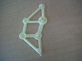
Triangle
[edit | edit source]Traditionally, the leg is formed by just using rods:
.jpeg)
When manufacturing from flat stock like paper or wood, realizing that that one leg can also be constructed from 2 triangles and 5 rods can simplify the assembly and make the mechanism more robust


here some practical examples:
-
 Leg mechanism made from card board
 -
 Mini Strandbeest


A fully-parametric strandbeest implemented in OpenSCAD, with assembly instructions, is available for 3D printing.[3]
Using Rod of the same length
[edit | edit source]f=39,4 and c=39,3 are so close in length, that using rods of the same length can simplify the assembly without affecting the gait to much.
Note that in practice, the whole mechanism as play and flex, undergrounds are not perfectly flat and lengths and holes have manufacturing inducted errors.
References
[edit | edit source]- ↑ https://ethanzuckerman.com/2007/03/08/theo-jansens-strandbeests/
- ↑ Linda Leinen (26 September 205). "Theo Jansen: Walking on the Mild Side".
- ↑ A. Matulich (23 May 2020). "Building the Strandbeest".