OpenSCAD User Manual/CSG Modelling
boolean overview
[edit | edit source]2D examples
[edit | edit source]-
 union ( or )
circle + square -
 difference ( and not )
square - circle -
 difference ( and not )
circle - square -
 intersection ( and )
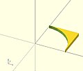
circle - (circle - square)


union() {square(10);circle(10);} // square or circle
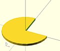
difference() {square(10);circle(10);} // square and not circle
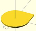
difference() {circle(10);square(10);} // circle and not square
intersection(){square(10);circle(10);} // square and circle
3D examples
[edit | edit source]-
 union ( or )
sphere + cube -
 difference ( and not )
cube - sphere -
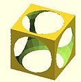
 difference ( and not )
sphere - cube -
 intersection ( and )
sphere - (sphere - cube)


union() {cube(12, center=true); sphere(8);} // cube or sphere
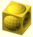
difference() {cube(12, center=true); sphere(8);} // cube and not sphere
difference() {sphere(8); cube(12, center=true);} // sphere and not cube
intersection(){cube(12, center=true); sphere(8);} // cube and sphere
union
[edit | edit source]Creates a union of all its child nodes. This is the sum of all children (logical or).
May be used with either 2D or 3D objects, but don't mix them.

 //Usage example:
 union() {
 	cylinder (h = 4, r=1, center = true, $fn=100);
 	rotate ([90,0,0]) cylinder (h = 4, r=0.9, center = true, $fn=100);
 }
Remark: union is implicit when not used. But it is mandatory, for example, in difference to group first child nodes into one.
Note: It is mandatory for all unions, explicit or implicit, that external faces to be merged not be coincident. Failure to follow this rule results in a design with undefined behavior, and can result in a render which is not manifold (with zero volume portions, or portions inside out), which typically leads to a warning and sometimes removal of a portion of the design from the rendered output. (This can also result in flickering effects during the preview.) This requirement is not a bug, but an intrinsic property of floating point comparisons and the fundamental inability to exactly represent irrational numbers such as those resulting from most rotations. As an example, this is an invalid OpenSCAD program, and will at least lead to a warning on most platforms:
 // Invalid!
 size = 10;
 rotation = 17;
 union() {
    rotate([rotation, 0, 0])
       cube(size);
    rotate([rotation, 0, 0])
       translate([0, 0, size])
       cube([2, 3, 4]);
 }
The solution is to always use a small value called an epsilon when merging adjacent faces like this to guarantee overlap. Note the 0.01 eps value used in TWO locations, so that the external result is equivalent to what was intended:
 // Correct!
 size = 10;
 rotation = 17;
 eps = 0.01;
 union() {
    rotate([rotation, 0, 0])
       cube(size);
    rotate([rotation, 0, 0])
       translate([0, 0, size-eps])
       cube([2, 3, 4+eps]);
 }
difference
[edit | edit source]Subtracts the 2nd (and all further) child nodes from the first one (logical and not).
May be used with either 2D or 3D objects, but don't mix them.

Usage example:
difference() {
	cylinder (h = 4, r=1, center = true, $fn=100);
	rotate ([90,0,0]) cylinder (h = 4, r=0.9, center = true, $fn=100);
}
Note: It is mandatory that surfaces that are to be removed by a difference operation have an overlap, and that the negative piece being removed extends fully outside of the volume it is removing that surface from. Failure to follow this rule can cause preview artifacts and can result in non-manifold render warnings or the removal of pieces from the render output. See the description above in union for why this is required and an example of how to do this by this using a small epsilon value.
difference with multiple children
[edit | edit source]Note, in the second instance, the result of adding a union of the 1st and 2nd children.

// Usage example for difference of multiple children:
$fn=90;
difference(){
                                            cylinder(r=5,h=20,center=true);
    rotate([00,140,-45]) color("LightBlue") cylinder(r=2,h=25,center=true);
    rotate([00,40,-50])                     cylinder(r=2,h=30,center=true);
    translate([0,0,-10])rotate([00,40,-50]) cylinder(r=1.4,h=30,center=true);
}

// second instance with added union
translate([10,10,0]){
    difference(){
      union(){        // combine 1st and 2nd children
                                                cylinder(r=5,h=20,center=true);
        rotate([00,140,-45]) color("LightBlue") cylinder(r=2,h=25,center=true);
      }
      rotate([00,40,-50])                       cylinder(r=2,h=30,center=true);
      translate([0,0,-10])rotate([00,40,-50])   cylinder(r=1.4,h=30,center=true);
    }
}
intersection
[edit | edit source]Creates the intersection of all child nodes. This keeps the overlapping portion (logical and).
Only the area which is common or shared by all children is retained.
May be used with either 2D or 3D objects, but don't mix them.

//Usage example:
intersection() {
	cylinder (h = 4, r=1, center = true, $fn=100);
	rotate ([90,0,0]) cylinder (h = 4, r=0.9, center = true, $fn=100);
}
render
[edit | edit source]Warning: Using render, always calculates the CSG model for this tree (even in OpenCSG preview mode). This can make previewing very slow and OpenSCAD to appear to hang/freeze.
Usage example:
render(convexity = 1) { ... }
| convexity | Integer. The convexity parameter specifies the maximum number of front and back sides a ray intersecting the object might penetrate. This parameter is only needed for correctly displaying the object in OpenCSG preview mode and has no effect on the polyhedron rendering. |

This image shows a 2D shape with a convexity of 4, as the ray indicated in red crosses the 2D shape a maximum of 4 times. The convexity of a 3D shape would be determined in a similar way. Setting it to 10 should work fine for most cases.