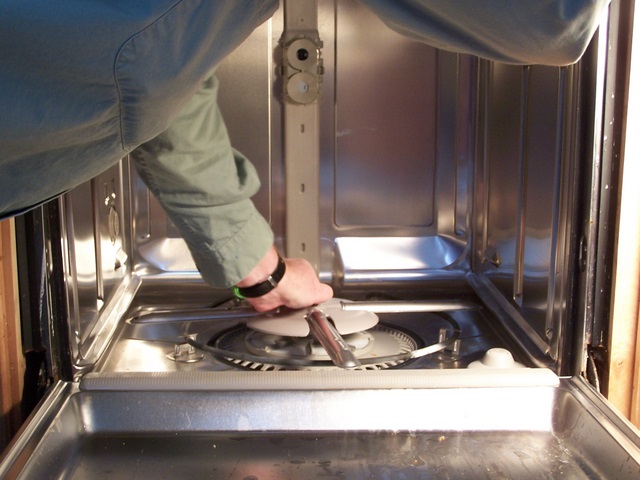
How To Repair Dishwashers/KitchenAid Repair/Chopper Replacement
Disassembly guide to access the chopper assembly in:
KitchenAid K series dishwasher (similar to Whirlpool and Kenmore models)
Model: KUDK03CTWH
Also works for model: Kenmore 655.15959000
Also works for models: KUDS03CTSS and KUDS301VBS3
Also works for model: KIDI02FR
Also works for model: KUDP01DLWH3
Also works for model: KUDL03IVWH3
The main differences were:
- Four instead of three torx screws to remove the filter unit
- A simpler chopper cover with one instead of two screws, and no 'hinged' flap
- The chopper has four blades instead of two.
- These models have the 'ProScrub' option, which means you have to pop the blue plastic ProScrub unit from the lower vertical section of the water conduit before trying to rotate the conduit 30 degrees clockwise.
Safety:
This disassembly exposes you to the chopper blades in this dishwasher. If the door safety interlock fails, the dishwasher could return to an active mode where these blades spin and would injure you. To be safe, remove power from the dishwasher before beginning this repair.
Goals:
Clean and/or replace the chopper unit. If the chopper does not function, the adjacent mesh filter will clog, there will be poor water flow through the dishwasher, and the items on the top shelf will not be washed. You can put a glass right-side-up in the top shelf to see if there is water being supplied to the top washer/spinner. If hard items such as toothpicks or pistachio shells find their way into the chopper compartment, the dishwasher will make a loud grinding sound whenever the pump is running. Cleaning such debris from the chopper compartment will eliminate the noise.
The chopper unit is easily destroyed by ingesting parts of a broken glass. This will shear off the stem of the shaft that drives the chopper blades. As noted below, the chopper can sometimes be repaired by melting the end of the plastic shaft and pressing with a flat piece of metal to expand the end sufficiently to keep the blade and other chopper parts locked to the shaft.
Tools Required:
Torqx screwdriver with T-15 and T-20 bits
Slip-lock or vice-grip pliers
Flat-head screwdriver
A video with slightly different instructions is available at http://www.youtube.com/watch?feature=player_embedded&v=lRDbTgBOtIE
Part to be replaced:
"chopper assembly"
Part Number: AP3039186 made by WHIRLPOOL
see for instance http://fixitnow.com/, http://www.appliancepartspros.com/
2) Remove clips in each of the top slider rails to allow removing the top basket. This is needed to make room to work and to remove the upper water conduit. There does not seem to be an easy way to remove the door, which would make this job easier. On some KitchenAid models it is difficult to remove/replace the slider rail clips as they do not have push-button release mechanisms. In this case you can leave the top rack in place and carefully work around it to remove the upper spray arm water conduit. On the KUDP01, the rail clips can be removed by depressing the locking tab on the top of the clip with a small screwdriver, and rotating the clip inward until it pops out of the rail.

3) Everything is cleared out of the way, ready to remove the lower spray arm.
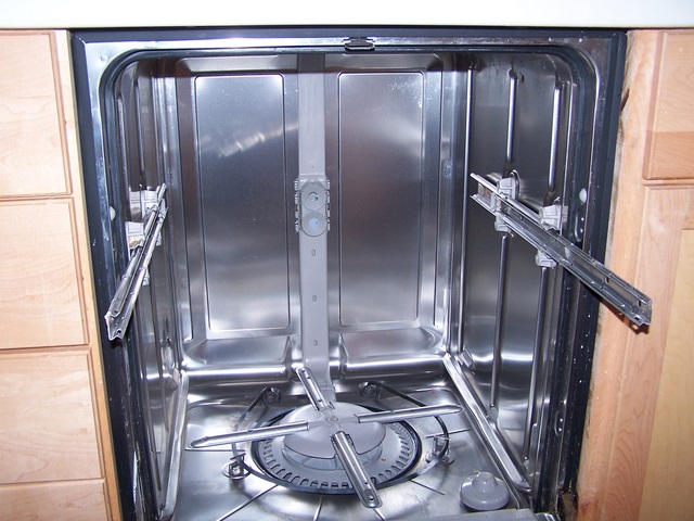
4) Remove the lower spray arm by un-screwing the center cap clockwise (yes this is the opposite of normal threading direction, the plug will go down and out the back of the spinner).
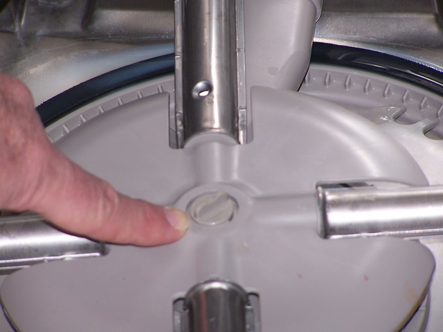
5) Both the fine filter (round 8") and the water conduit leading back and up to the top will need to be removed.

6) The water conduit has to be removed. It might be possible to take it apart, but the more direct approach is to release the back (here) clip, and the top clip. Take care when "removing" these clips as they bend easily and will need to be re-bent to properly clip back onto the water channel if damaged.

7) A similar clip must be released at the top:
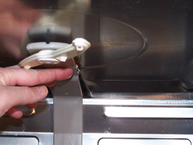
8) With the water conduit released from the clips, the whole assembly must be rotated thirty degrees clockwise about the central pump outlet. This will release this plastic item from its bayonet mount there so it can be removed.

9) Remove this thing. There's a flat nylon washer on the bottom.

Don't lose it.
10) Remove first of three T-20 torqx screws to release the filter. The screws are at ten o'clock, eight o'clock and 4'clock. Some units have a fourth screw, also at ten o-'clock. The eight o'clock screw is being removed in the photograph.

11) Remove the second of three torqx screws to release the filter. This is the ten o'clock screw.

12) Remove the third of three torqx screws to release the filter. This is the four o'clock screw.
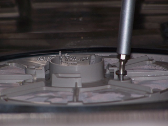
13) If present, remove the fourth screw. Remove the filter and base. The fine filter (circular plastic assembly) snaps on to the larger base unit. As long as you have it out, you might as well clean the inside of any accumulated guck. Using a flat screwdriver, carefully pry the circular plastic rim up from the base. The fine filter pops off. Clean out any debris, then snap the fine filter back on to the base unit. Be careful not to damage the filter mesh.
If you're wondering about the white doohickie sticking up at the right side (3 o'clock position), that's a thermistor. It measures the temperature of the wash water. The control unit will activate the heating element if your HW supply is not sufficiently hot.

14) Top view of the exposed sump and chopper assembly (under the cover on the bottom left). Finely filtered water is drawn into the pump through the small inlet pipe at 5 o'clock. The pump output is in the center. There is a coarse filter formed by the slotted cover at 7 o'clock (and below) that passes water to the chopper unit. The details of the water flow are unclear to me, but apparently a large fraction of the water flows through the chopper; because blocking this severely reduces the water flow out through the pump.

15) Remove the first of two T-15 torqx screws in the top chopper cover. There is a second screw to the right side (at 6 o'clock in this photo). If you are clever, if you leave the screws in the top chopper cover, then it is easy to track which screw goes where.

16) Lift off the top cover. At this point the hemi-cylindrical inner cover should lift off, but I found it to be tightly wedged into its mounting flanges, and it would not move. The cover is "hinged" by a clip on the right-hand side and should pivot from the left edge up and over toward the check valve cover on the right. There is a tight friction fit of this cover with the sump. Perhaps by grasping under the bottom edge of the cover and right-hand-side tabs it can be dislodged. I used 8 inch slip lock pliers to grasp the small tab on the top of the cover and wiggle it free. You can see the tab you are trying to get around in the second photo below, highlighted by the red arrow. COMMENT: I tried that but the tab started to disintegrate. A better alternative; slide the edge of a paint can opener with the handle leaning to the right under the left edge of the cover, move the handle to the left until it is vertical, and then use it to lift the left edge of the cover up. NOTE: There is a small recess on the screw side that is made to fit a screwdriver blade in to rotate the cover up. It's vertical, on the rounded part of the cover. Needlenose pliers can also be used to gently grasp the screw hole on the left side of the cover and then you can lift the cover out. This might be the only way to free a stuck cover if the tab is broken or too worn to be grasped with pliers.

17)The old chopper. If it is not broken, just clogged, clean the screen and reassemble. A clean chopper screen will make a surprisingly large difference in the water flow through the rotating arms. If there is any debris in the chopper compartment (immediately in front of the chopper screen), remove it. Any hard ungrindable items will spin round and round and make a horrible clatter.

18)The old chopper removed.To remove the old chopper, pull the blade towards the front of the machine so that the white nylon drive pawl disengages from the impeller. While holding the blade forward, lift the screen straight up. If you are lucky and the shaft is not badly damaged, just the end cap is no longer holding, the chopper can be repaired by putting the components in place on the shaft and melting the end of the plastic shaft with a flame and then quickly pressing flat with a knife blade to expand the end and lock on the blade and washer etc. This is likely not a permanent fix so a new chopper should be ordered. It will get you back up and running in the short term.
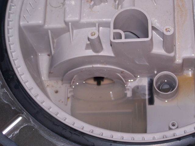
20)The new chopper installed. Note that it fits into the outer, narrower slot. To easily install the new chopper, grasp the screen and pull the blade away from it. This compresses the spring and prevents binding of the shaft when lowering the screen into place. Then insert a spacer (crescent wrench works well) between the blade and the screen. This keeps the shaft out of the way so you can lower the screen into its slot. Note the notches in the screen, the narrow side goes down. Also, sometimes, installing the chopper at an angle allows the shaft to more easily slide over the main shaft. Once in place, remove the spacer and the shaft will snap back into position. You may have to rotate the blade back and forth a bit to get the nylon drive pawl to fully engage with the impeller. Note: It's important to press the chopper cover right up against the plastic wall when you install it back in so that the screen properly engages with the groove in the cover. If the screen doesn't engage correctly, your dishwasher will make a horrible racket, and possibly damage the cover!

21)Putting it back together. The "Thing" (above) goes in before the water conduit and should sit loosely. Do not press it down.
Screw the lower spray arms (cross shaped) onto the Thing.
If it turns freely without screwing in, you need to pull up on the center cap while turning spray arms clockwise.
22)There is the correct water level.
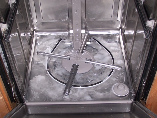
Done.


