Electronics/Transformers
Transformer
[edit | edit source]Description
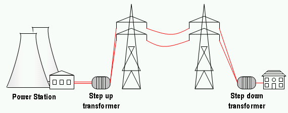
A transformer is a device that is used to either raise or lower voltages and currents in an electrical circuit. In modern electrical distribution systems, transformers are used to boost voltage levels so as to decrease line losses during transmission.
Theory of Operation
Transformers rely on Faraday's Law, which states that a time-varying magnetic field can induce a time-varying voltage in a loop of wire. In a transformer, this is accomplished by wrapping multiple turns of wire around some type of ferromagnetic material. Usually, there are two sets of windings: a primary and a secondary. The primary winding is attached to the generator; the secondary side is attached to the load. When a time-varying voltage is applied to the primary, a magnetic field is created inside the ferromagnetic core. The ferromagnetic material serves to concentrate the magnetic flux within the windings. The magnetic flux on the outside of the windings is reduced and the efficiency of the device is increased.
The time-varying magnetic field induces a voltage in the secondary winding.
The magnitude of the secondary voltage depends on the turns ratio of the primary and secondary windings. Suppose that the secondary winding of a transformer has 100 turns, while the primary winding has only 50 turns. The resulting secondary voltage will be twice that of the primary voltage. Likewise, if the primary has 100 turns, and the secondary has 50 turns, the secondary voltage would be half that of the primary.
At this point it may seem that we're getting something for nothing, but this is not the case. Recall that energy can neither be created nor destroyed. We know that the electrical power flowing into the primary windings is the product of the current and voltage. Similarly, the power flowing out of the transformer must also be product of its current and voltage. Neglecting losses in the transformer core, the power entering the transformer must also be the power leaving the transformer. This means that in order to raise the voltage, we must decrease the current. Likewise, by lowering the voltage, we increase the current. As with the transformer voltages, the ratios of the currents depend on the ratios of the primary and secondary windings. However, when dealing with currents, it is important to remember that the side with the larger number of turns has the smaller current and vice versa. Consider the transformer mentioned above with a primary to secondary turns ratio of 1:2. A 100-A current flowing into the primary would result in a 50-A current flowing out of the secondary.
Uses
The most obvious application of the electrical transformer is in power distribution. Recall that in an electrical circuit, . Therefore, the power consumed by a circuit element is proportional to the square of the current flowing through it. In a transmission line, this is important because the line itself has some characteristic impedance. In order to reduce power losses in the transmission line, it is desirable to transmit the least amount of current possible. For a given amount of power, the best way to do this is by increasing the voltage.
The transformer is also used for impedance matching. Given a voltage source and a transmission line with a characteristic impedance, it is possible to use a transformer to make the load appear larger or smaller so that the load receives maximum power. Note that maximum power is not equal to maximum efficiency. For maximum efficiency in the use of electrical energy, the load should have extreme resistance so that the energy lost in the rest of the circuit will be negligible. Looking into the equations, however, the load of extreme resistance will receive negligible power (though much higher than the rest of the circuit). For any given constant voltage across any load, the power received by the load is given by , thus the relationship. Note again that the equation used here is the one above transformed with Ohm's Law, and is the only appropriate since Current will drop in this case if the resistance increases.

3-phase transformers
[edit | edit source]These are, in essence, 3 single-phase transformers that have one of their terminals connected to a common terminal, called the neutral, which usually is connected to earth/ground. Their voltages are 120 degrees out of phase from the other two.


