Computer network technologies and services/Print version
| This is the print version of Computer network technologies and services You won't see this message or any elements not part of the book's content when you print or preview this page. |
The current, editable version of this book is available in Wikibooks, the open-content textbooks collection, at
https://en.wikibooks.org/wiki/Computer_network_technologies_and_services
WAN
Strictly speaking, a Wide Area Network (WAN) is a network that is extended over a broad area, spanning regions, countries or in the case of the Internet even the world. More generally, any computer networking technology used to transmit data over long distances can be called as a WAN.
A WAN technology should meet some requirements in terms of service duration, bit rate and delay constraints according to the application (telemetry, telephony, data transfer, etc.) it is designed for.
Asynchronous Transfer Mode (ATM) represents the convergence for a wide variety of technologies that in the past both telecom and IT worlds in parallel introduced in order to transmit data over long distances:
- in the telecom world, the telephony turned from analog to digital, then ISDN and B-ISDN started to carry data along with the voice;
- in the IT world, Frame Relay superseded analog and digital leased lines by taking advantage of packet switching, and X.25 by moving the complexity from core to edge nodes.
Nowadays ATM is going to be abandoned in favour of IP thanks to its lower complexity and greater simplicity.
ISDN
[edit | edit source]Integrated Service Digital Network (ISDN) allows to carry data along with the voice: a variety of digital devices can be connected to a bus and can transmit over the available ISDN channels:
- Basic Rate Access (BRA) or Basic Rate Interface (BRI): it offers 2 data B-channels at 64 kbps and 1 signaling D-channel at 16 kbps → total: 144 kbps (good for single users or small offices);
- Primary Rate Access (PRA) or Primary Rate Interface (PRI): it offers 30 data B-channels at 64 kbps and 1 signaling D-channel at 16 kbps → total: 2 Mbps (good for companies).
The transmission is based on Time Division Multiplexing (TDM); all channels go to a Network Termination and enter the network over a digital wire called 'local loop'. The channels inherit the logics from telecom operators: they keep being alive also when no data is exchanged.
PDH
[edit | edit source]
Plesiochronous Digital Hierarchy (PDH) is an old standard designed to transfer digital voice channels at 64 Kb/s (PCM) over TDM-based digital telephone networks. The system is called 'plesiochronous' because a tight synchronization between transmitter and receiver is required, even if each device has its own clock.
Data flows are organized in a hierarchical way: channels are aggregated into flows from the lowest layer to the highest one (grooming), and the higher the hierarchical layer, the higher is the bit rate. For example, at layer T1 24 T0-layer channels are put into a single frame one next to another: as the frame has to last 125 µs for all layers, at layer T1 the bit rate will be 24 times higher than the one at layer T0.[1]
SDH
[edit | edit source]
Synchronous Digital Hierarchy (SDH), the European equivalent of the international standard SONET, differs from PDH for its higher speeds:
- a single clock exists for the whole system → a synchronization network is required for a tighter synchronization;
- copper cables need to be replaced with optical fibers;
- the flow multiplexing is more complex than PDH, because it is designed to optimize the hardware processing.
The protocol architecture is organized as a layer stack, and each node in the physical network architecture implements them according to its functionality:
- path layer: end-to-end interconnection between two terminals;
- line layer: a path is split into lines by multiplexers;
- section layer: a line is split into sections by repeaters (for long distances);
- photonic layer: the lowest layer for optical fibers.
Each time frame lasts 125 µs and its header includes synchronization information used to combine and separate channels, and OAM (Operation, Administration and Management) information used to detect failures and recover from them.
SDH and PDH represent the transport layer which ATM and Frame Relay operate on.
Frame Relay
[edit | edit source]Frame Relay is a layer 2 connection-oriented standard to set up permanent virtual circuits over packet-switching networks. Each permanent circuit is identified by a Data Link Connection Identifier (DLCI).
The standard is very flexible: in fact it does not specify the technology at upper layer (ATM, X.25...) used internally in the network.
CIR
[edit | edit source]
The maximum supported bit rate is not enough to describe the performance of a Frame Relay network, because an user may send bits consecutively at the maximum bit rate (wire speed) for a long period of time causing congestion in the network. Therefore the network provider provides also the Committed Information Rate (CIR), that is the maximum number of bits the user can transmit within a certain interval of time so that the service is guaranteed:


where is called committed burst size:
- low burstiness: the user rarely sends packets → the service is always guaranteed;
- high burstiness: the user keeps sending packets consecutively at wire speed → when he exceeds the committed burst size the service will not be guaranteed anymore.
The user's Data Terminal Equipment (DTE) can stop the transmission when the maximum burstiness is reached.
ATM
[edit | edit source]Asynchronous Transfer Mode (ATM) is a connection-oriented standard to set up virtual circuits over B-ISDN networks. Each circuit is identified by a Virtual Path Identifier (VPI) and a Virtual Circuit Identifier (VCI), and it can be permanent or dynamically set up through signaling messages.
ATM cells are very small: each ATM cell is 53 bytes long, made up of a 5-bytes-long header, containing the connection identifiers, and a 48-bytes-long payload → low latency and low packetization delays.
ATM networks have a very complex model, derived from a telecom-operator mentality to have the full control of the network and guarantee a high fault tolerance.
AAL 5
[edit | edit source]When ATM was designed, it was thought to be implemented ubiquitously in the network, also at its edges in the network cards of the user PCs. Nowadays PCs at the edges are implementing only the IP protocol because its implementation is cheaper, and ATM can be found only as transport layer in the core of the network hidden from the user.
ATM Adaptation Layer (AAL) of type 5 is used for Segmentation and Reassembly (SAR):
- Segmentation: IP packets are split into ATM cells;
- Reassembly: ATM cells are combined into IP packets.
AAL makes interaction between IP and ATM complex, because IP addresses should be translated to ATM connection identifiers and vice versa → nowadays the tendency is abandoning the ATM control plane and adopting the MPLS control plane.
Optical networks
[edit | edit source]In optical networks data are transmitted over electromagnetic waves multiplexed by using WDM, transported via optical fibers and switched by mirror-based optical switching systems.
Wavelength Division Multiplexing (WDM) allows to put multiple optical signals into a single optical fiber → the transmission capacity of fibers is increased:
- Coarse WDM (CWDM): it allows to transmit a lower number of signals with wavelengths well-separated one from each other → cheaper because demultiplexing is easier;
- Dense WDM (DWDM): it allows to transmit a higher number of signals with any wavelength → more expensive because demultiplexing is more complex.
Optical switching is based on mirrors controlled by micro-electro-mechanical systems (MEMS), reflecting electromagnetic signals from an input fiber to an output fiber. Optical switching is very flexible: it exploits physical properties of electromagnetic waves without caring about bits → networks can be upgraded to higher speeds because optical switches keep working independently of the bit rate.
Several types of optical switches exist:
- add/drop multiplexer: it is the simplest optical switch: it can be interposed between two fibers to optically insert (add) signals coming from transmitters into the network, and extract (drop) signals from the network towards the receivers;
- cross-connect: it can connect multiple input fibers to multiple output fibers:
- fiber cross-connect: all the electromagnetic waves coming from an input fiber are switched to an output fiber;
- waveband cross-connect: a set of electromagnetic waves with close wavelengths coming from an input fiber is switched to an output fiber;
- wavelength cross-connect: a set of electromagnetic waves with the same wavelength coming from an input fiber is switched to an output fiber;
- wavelength switch: configuration is dynamic, that is switches can change circuits faster than cross-connects → fault recovering is fast.
Two signals with the same wavelength may be coming from two different input fibers but they may need to be switched to the same output fiber → through the wavelength conversion an optical switch can change the wavelength of a signal to one not still used in the output fiber, in order to keep all signals separated.
Optical switches can be used in the network backbone to interconnect the major access points, by setting up optical paths via optical fibers among the cities in the world. Optical switches can set up optical paths by using signaling and routing protocols such as LDP and RSVP. Optical switches are fault tolerant: when a link breaks, they can reflect the waves along another optical path.
WDM can be deployed as the transport layer on which any layer 2 protocol (SONET, Ethernet...) can operate delimiting the frames.
However the technology for pure optical switching is still in an embryonic stage: nowadays WDM switches are more expensive than packet-switching ones, and they can have few interfaces because the mirror system would be very complex for a lot of interfaces. Moreover optical switching is connection-oriented: when a circuit is set up, the resources keep being allocated even if the circuit is not currently used → optical switching is good for the network backbone where the traffic is quite continuous.
Cheaper solutions try to overcome technological limits by replacing mirrors with an electrical switching matrix: each optical signal is converted to a sequence of bits through an optical-to-electrical (OE) conversion so that it can be switched more easily, then it is converted again into an optical signal. The reconverted signal is regenerated, being able to travel for a longer distance before losing power, but this solution has a lot of disadvantages: the switches consume a lot of power with respect to all-optical switches, and changing the bit rate requires to upgrade the switches.
References
[edit | edit source]- ↑ Signaling bits are not considered.
MPLS
Multiprotocol Label Switching (MPLS) is the enabling technology for the new broadband (IP) public network. It can be considered as a protocol architecture (or a suite of protocols) to control different sub-protocols.
MPLS operates at a layer that is generally considered to lie between traditional definitions of layer 2 (data-link layer) and layer 3 (network layer).
Benefits
[edit | edit source]- MPLS introduction simplifies the traditional 'big onion'.
-

-


IP protocol was developed for research purpose and was not designed to be sold as a service. It is a so-called 'best-effort protocol', which means that there is no explicit purpose in giving a guaranteed reliable service (speed, delays...).
When IP was starting to become a commercial good, the International Telecommunication Union (ITU) started developing protocols (such as ATM, frame relay, etc.) targeting service reliability and stability, thinking they would have been permeating the computer telecommunication world. Nevertheless end users have kept using IP, and as a result service providers nowadays have to deal with a lot of protocols in order to carry IP to end users: this 'big onion' makes very few sense for service providers due to high maintenance, equipment and software development costs to guarantee interoperability.
Cisco Systems was the first vendor to implement tag switching into their routers, then IETF adopted the protocol and named it as MPLS.
MPLS combines the best features from the connection-less protocols with the best ones from the connection-oriented protocols, representing the solution for the 'big onion' problem for two reasons:
- MPLS provides an IP-based network with a greater service reliability and a single unified control plane more isolated from the data plane:
- in IP control and data planes are continuously updated on every change in the network;
- in MPLS updating occurs just when a new LSP is set up; since there is a separation between data plane and control plane it is possible to set up paths with independent constraints;
- MPLS allows to re-use the traditional ATM devices by simply updating their software.
- Main features
- possibility of \ul{traffic engineering}: distributing traffic load over the network to avoid congestions;
- protocol independence (multi-protocol) → useful for transition from IPv4 to IPv6;
- designed to grant quality of service (not yet supported);
- unified control plane: it can be used for any network besides IP (e.g. MPλS for optical networks);
- fast fault recovery: two paths between a pair of nodes can be created, so that in case of failure in the first path the LSR can just notify the failure and quickly deviate the traffic to the second path[1] (instead in IP it is difficult to insert two paths into a routing table, and if a link fails routers need to exchange routing information and perform sophisticated algorithms to find another path).
Network architecture
[edit | edit source]
A Label Switch Router (LSR) is the device responsible for switching the labels used to route packets. LSRs are called label edge routers when placed at the edges of the MPLS cloud. LSRs combine smartness of routers and speed of switches: they are able to route in a clever way like routers, avoiding complicated data structures and algorithms like switches.
MPLS clouds can be gradually deployed: they can grow up and can be integrated to each other.
Data plane
[edit | edit source]Data plane is the capability of switching packets based on their labels.
MPLS header
[edit | edit source]
IP packets are prefixed with an MPLS header containing one or more label stack entries. Each label stack entry contains four fields:
- label: routing is based on this field instead of the IP destination address;
- traffic class (exp): for quality of service (QoS) priority and Explicit Congestion Notification (ECN);
- bottom of stack flag (S): if set, the current label is the last one in the stack;
- Time to Live (TTL).
Label switching
[edit | edit source]
A Label Switched Path (LSP) is a path set up by a signaling protocol that links a source label edge router (ingress) to a drain one (egress):
- when the ingress LSR receives a packet, it adds a label to it and forwards it to the next hop of the LSP previously created;
- when the egress LSR receives a packet, it strips off its label and forwards it out of the MPLS cloud.
A Forwarding Equivalence Class (FEC) is a set of packets which may be forwarded in the same way; that is, they may be bound to the same MPLS labels. Labels are not unique over the whole MPLS cloud, but they are changed on each hop (label swapping). Consider that granting the uniqueness of the labels all over the network would require too complex protocols and too long labels.
Using labels enables MPLS to provide two kinds of services:
- fast lookup: IP routing, based on the `longest prefix matching' algorithm, is sophisticated, difficult to be optimized and not fast enough when dealing with a wide amount of routes.
- MPLS provides a faster lookup with respect to IP because packet-forwarding decisions are made solely on the label, placed before the IP packet, without the need to examine the contents of the packet itself: each label in fact can be used as key to access the routing table as an array or hash table in order to expedite the route discovery;
- traffic engineering: IP tends to aggregate the traffic, but having lots of packets going through the same path doesn't provide an efficient service. This can not be avoided easily as it would require a static route configuration → expensive and not scalable.
- MPLS is able to control the traffic like a connection-oriented protocol: MPLS routing involves both source and destination labels, and routers can assign to a new packet flow the label corresponding to the least-loaded path in order to avoid congestion and allow traffic distribution. Moreover a failure in a path due to a non-working node will not affect the other paths.
Hierarchy and scalability
[edit | edit source]
MPLS is very scalable: inside a big MPLS cloud of domain 1 it is possible to define in a hierarchical way a smaller MPLS cloud of domain 2 and so on, and multiple label stack entries can be stored next to each other in a stack data structure. The label stack entries are added from the inner one to the outer one while the packet enters clouds of higher domain and stripped off from the outer one to the inner one while the packet exits clouds of lower domain, and LSRs not at the edges of the clouds always process the outer label stack entry. This hierarchy of labels can correspond to a hierarchy of providers, and the number of labels is limited only by the Ethernet frame size.
This technique introduces some advantages:
- it reduces the size of the routing and forwarding tables, because they do not have to be comprehensive;
- it allows to re-use the existing switching hardware (ATM, frame relay, etc.): MPLS headers are put directly into the 2-level headers, so that they can be processed by the existing hardware that now processes the level 2 simply by upgrading its software.
Control plane
[edit | edit source]Control plane is the capability of choosing the labels to be inserted into the packets.
The creation of a forwarding table (and in a broader sense of the LSP) for a specific FEC is performed in three steps:
- label binding: it is always performed by the downstream node, which chooses a label for the FEC, and this can be performed in two ways (not mutually exclusive):
- unsolicited: the downstream node can decide any time to assign labels, even if there is no traffic in the network;
- on-demand: the upstream node can asks the downstream node for a fixed label;
- label distribution: the downstream node communicates the chosen label to the upstream node;
- label mapping: the upstream node creates a new entry in its forwarding table by binding incoming packets, coming from a specific port with a specific label, to outcoming packets, going out of a specific port with a specific label.
Labels can be assigned in two ways:
- statically: network manager sets LSPs manually, like permanent virtual circuits (PVC) in connection-oriented technologies like ATM → this solution does not scale and limits the interoperability among different service providers;
- dynamically: label binding, distribution and mapping are performed automatically by LSRs without manual intervention:
- data-driven: the creation of an LSP is triggered by the reception of data packets, and each LSR autonomously chooses labels based on the traffic;
- control-driven: at some point the LSR assigns a label, even if there is no traffic;
- topology-driven (or protocol-driven): whenever a new destination is discovered, an LSP is created towards this destination → no traffic engineering: the network works exactly like an IP network;
- explicit: the creation of LPSs, usually initiated by label edge routers either data-driven or by manual configuration, is performed through explicit signaling.
Protocols
[edit | edit source]Label distribution protocols
[edit | edit source]Three protocols, incompatible to each other, can be used by the downstream node in order to communicate to the upstream node the label bindings:
- Label Distribution Protocol (LDP): designed specifically for label distribution;
- extended Border Gateway Protocol (BGP): the downstream node includes in BGP routing messages, used to advertise new destinations, a new field that tells the upstream node the chosen labels (only for protocol-driven label binding);
- extended Resource Reservation Protocol (RSVP): the downstream node includes in RSVP messages, used to notify the traffic types of packet flows for quality of service, a new field that tells the upstream node the chosen labels:
 Computer network technologies and services/Quality of service.
Routing protocols
[edit | edit source]The traditional routing protocols can be enhanced to support traffic engineering because they carry information about routing constraints.
Thanks to routing protocols such as OSPF-TE and IS-IS-TE (based on OSPF, IS-IS, BGP-4), every node can collect information about the network topology in order to know which nodes are its upstream nodes to be notified with the label bindings.
There are two possible routing strategies:
- hop-by-hop (as it is in IP routing): distributed routing protocol where each LSR decides by itself according to the shortest path criterion, so it may happen that all routers choose the same path → risk of congestion;
- explicit (possibility of constraint-based routing): centralized routing protocol where the egress LSRs are advertised to understand which links are currently the most loaded ones and choose the least loaded links for creating new LSPs so that they are disjointed as much as possible from other paths.
- In order to support explicit routing, the basic distribution labels should be extended:
- Constraint-based Routing LDP (CR-LDP) is an extension to LDP;
- RSVP for Traffic Engineering (RSVP-TE) is an extension to RSVP.
References
[edit | edit source]- ↑ An overhead is required to keep available two LSPs for the same FEC.
IPv6
Internet Protocol version 6 (IPv6) is a new protocol aimed to overcome IPv4 limits: the main reason for introducing a new protocol is to have a larger address space with respect to the IPv4 one.
Comparison to IPv4
[edit | edit source]IPv6 expands ICMP protocol by integrating the following protocols:
- ARP: called 'neighbor discovery' for address configuration process;
- IGMP: called 'Multicast Listener Discovery' to manage multicast group memberships.
With IPv6 some protocols need just to be upgraded, mainly due to the fact that they all deal with addresses (these protocols are not layer-3 independent):
- DNS protocols;
- routing protocols: RIP, OSPF, BGP, IDRP;
- transport protocols: TCP, UDP;
- socket interfaces.
IPv6 additional features
[edit | edit source]The additional features listed below were originally designed as add-ons for IPv4, then they were ported to be embedded into IPv6.
- Deployment on LANs
It is more efficient, thanks to an efficient usage of multicast and anycast addresses:
- multicast: each multicast address identifies a group of stations, and the packet is forwarded to all the nodes in the group;
- anycast: each anycast address identifies a group of stations, but the packet is forwarded just to the closest node in the group.
- Data security and privacy
Security mechanisms such as IPsec are included in the IPv6 protocol.
- Policy routing
It is the possibility to forward packets by using policies different than the destination address (e.g. forwarding by source address).
- Plug and play
Autoconfiguration protocols are defined:
- stateless: only link-local access is guaranteed without contacting any server;
- stateful: it is possible to have access to the Internet by using a DHCP server.
- Traffic differentiation
Not all data flows are equal (e.g. phone calls require less delays).
- Mobility
It is the capability of moving the device across different networks while keeping available all services (e.g. mobile devices that use GSM/LTE moving around different cells).
- Nomadicity
It is the capability of moving the device across different networks without needing to grant the services active → less strict than mobility.
- Better scalability with routing
As a general rule aggregation is required to make routing easier but it requires a waste of addresses. IPv6 routing uses almost the same techniques as IPv4 but it can reduce the routing tables, if the addresses are given in an efficient way.
Addressing
[edit | edit source]Address format
[edit | edit source]Each IPv6 address is 128-bit-long, and the prefix replaces the netmask:
| prefix | interface identifier |
Links
[edit | edit source]The concept of link in IPv6 is the same as the concept of subnetwork in IPv4:
- in IPv4 a subnetwork is a set of hosts with the same prefix;
- in IPv6 a link is the actual physical network.
All the hosts in the same subnetwork belong to the same link and vice versa:
- on-link hosts have the same prefix, so they can communicate directly;
- off-link hosts have different prefixes, so they can communicate through a router.
Addressing space organization
[edit | edit source]Global unicast addresses
[edit | edit source]Aggregatable global unicast addresses
[edit | edit source]They are equivalent to the IPv4 public addresses, and they begin with the three bits '001':
| 3 | 16 | 48 | 64 | 88 | 96 | 104 | 128 |
| 001 | ID TLA | ID NLA | ID SLA | OUI ('universal' bit = 1) | FF | FE | manufacturer-selected MAC portion |
| prefix | interface identifier (EUI 64) | ||||||
- Prefix: it must be the same as the one assigned to the link which the host is connected to.
- Assignment criterion for prefixes is topology-based: they are assigned according to the service provider hierarchy:
- Top Level Authority (TLA): a large service provider;
- Next Level Authority (NLA): an intermediate service provider;
- Subnet Level Authority (SLA): the organization.
- Interface identifier: it identifies the host interface.
- Optionally it can be in EUI-64 format: the 64-bit IPv6 interface identifier derives from the host's 48-bit MAC address:
| 24 | 48 |
| OUI ('universal' bit = 0) | manufacturer-selected MAC portion |
- where the 'universal' bit is the seventh bit in the OUI and it is changed from 0 to 1.
Addresses for IPv4 interoperability
[edit | edit source]They are to be used during the transition phase, and they begin with 80 bits set to zero:
- IPv4-mapped addresses: the first 80 bits are zeros and the next 16 bits are set to one:
| 0000 | 0000 | 0000 | 0000 | 0000 | FFFF | ... |
- IPv4-compatible addresses: the first 80 bits are zeros and the next 16 bits are set to zero (e.g. the IPv6 address '::10.0.0.1' maps the IPv4 address '10.0.0.1'):
| 0000 | 0000 | 0000 | 0000 | 0000 | 0000 | ... |
Local unicast addresses
[edit | edit source]Link local addresses
[edit | edit source]They refer to the 'automatic' private addresses, generated by autoconfiguration, which is the process where a station automatically generates an address to connect to an IPv6 link:
| FExx | ... |
Site local addresses
[edit | edit source]They are equivalent to the IPv4 private addresses:
| FDxx | ... |
Multicast addresses
[edit | edit source]A multicast address identifies a group of stations and it has the following format:
| 8 | 12 | 16 | 128 |
| FF | Flag (000T) | Scope | Group ID |
where the fields are:
- Flag field (4 bits): it is used to mark a multicast group:
- T = 1: the multicast group is temporary (e.g. user-defined conference call);
- T = 0: the multicast group is permanent (e.g. address of all the hosts in the network, it can not be overwritten);
- Scope field (4 bits): it is used to limit the diffusion of the multicast (better than IPv4 TTL):
- 1 = node local: the packet can not go outside the host;
- 2 = link local: the packet can not go outside the layer 2 network;
- 5 = site local: the packet can not go outside e.g. the campus network;
- 8 = organization local: the packet can not go outside the organization network;
- E = global: the packet can go everywhere;
- Group ID field (112 bits): it identifies the multicast group, and the packet is forwarded to all the nodes in the group.
If a host wants to belong to a multicast group, it needs to ask for it by using the ICMP protocol; once it is added to the multicast group, it will receive all the packets sent to that particular multicast address. It is very important to notice that the hosts that will receive a multicast packet are not defined by the source, but they are 'decided' by the destinations.
Solicited node multicast addresses
[edit | edit source]Every operating node by default belongs to a solicited node multicast group whose address derives from its IPv6 address:
| 96 | 104 | 128 |
| FF02::1 | FF | 24 least significant bits from the IPv6 address |
There may be more than one host in the same multicast group, but generally there are not since the multicast address is generated from the IPv6 address.
Mapping IPv6 over Ethernet
[edit | edit source]Each multicast packet is delivered through an Ethernet frame with a specific MAC address derived from the IPv6 multicast address, so that the packet is processed just by the interested hosts:
| 16 | 48 |
| 3333 | 32 least significant bits from the target IPv6 address |
Advanced topics related to IPv6 addresses
[edit | edit source]Renumbering
[edit | edit source]As the prefixes for global addresses are assigned according to the service provider hierarchy, if a company wants to change from a service provider to another one, all the links in the company network will have to change their prefixes. IPv6 is meant to support easy renumbering for both hosts and routers:
- hosts: routers gradually stop advertising the old prefix (deprecated) and start advertising the new one (preferred) → each host will have during the migration phase two addresses with different prefixes for the same interface;
- routers: Router Renumbering is a standard which allows the border router to notify the other internal routers of the new prefix.
However renumbering still has some unsolved problems, related to how to automatically update e.g. the DNS entries, firewall filters, address-based corporate policies, etc.
Multi-homing
[edit | edit source]
A big company may decide to buy Internet connectivity from two different service providers because it wants to keep being connected to the Internet even if one of the service providers has some problems.
As the prefixes for global addresses are assigned according to the service provider hierarchy, each host inside the company network will have two global addresses with different prefixes for the same interface → the host will have to select which address to use for every outcoming packet. This may cause some non-trivial configuration problems:
- routing based on destination address: the host should be able to select the right prefix for outcoming packets, otherwise let us suppose the host selects the provider A's prefix but the destination is in the provider B's network → the border router thanks to its routing mechanisms will forward the packet directly into the provider B's network → the provider B will block that packet because the source address has a different prefix;
- double registration in DNSes: the host should be registered in DNSes by two different addresses for the same alias;
- automatic renumbering: renumbering mechanisms should dynamically support a change from a provider B to a provider C.
Scoped addresses
[edit | edit source]
A host can have two interfaces (e.g. an Ethernet interface and a wi-fi one) which can be connected to two different links at the same time. When the host wants to send a packet to a link local target address, it does not know whether to make the packet exit the interface A or the interface B, because both the links have the same prefix; moreover, as each link local address is unique within its link, a host in the link A may have the same link local address as another host in the link B.
In IPv6 the host needs to specify in the target IPv6 address an identifier called scope which is used to identify the physical interface (e.g. FE80::0237:00FF:FE02:A7FD%19). The values for the scopes are selected by the operating system according to its internal criteria.
Standard IPv6 header
[edit | edit source]The standard IPv6 header has the following fixed-size (40 bytes) format:
| 4 | 12 | 16 | 24 | 32 |
| Version (6) | Priority | Flow label | ||
| Payload length | Next header | Hop limit | ||
| Source | ||||
| address | ||||
| Destination | ||||
| address | ||||
where the most significant fields are:
- Version field (4 bits): it is not really used, because the packet discrimination is made by the layer 2 → this enables the dual-stack approach ( Computer network technologies and services/Migration to IPv6#Migrating operating systems);
- Priority field (8 bits): equivalent to the IPv4 'Type of Service' field, it allows to distinguish different kinds of services for quality of service ( Computer network technologies and services/Quality of service#Architecture);
- Flow label field (20 bits): it allows to distinguish different flows for quality of service;
- Next header field (8 bits): it refers to the packet payload, that is a header at upper layer (e.g. TCP/UDP) or the first extension header in the chain ( #Extension headers);
- Hop limit field (8 bits): it is equivalent to the IPv4 'Time To Live' field;
- Source address field (128 bits): it contains the sender's IPv6 source address for the packet;
- Destination address field (128 bits): it contains the addressee's IPv6 destination address for the packet.
Some IPv4 fields have been removed:
- Checksum field: error protection is delegated to layer 2 (frame check sequence);
- Fragmentation field: fragmentation is delegated to the 'Fragment' extension header;
- Header length field: IPv6 header is fixed-size, as additional features are optionally offered by extension headers.
Extension headers
[edit | edit source]There are six extension headers, added only when needed and processed in the following order:
- Hop by hop option: it includes optional information to be processed by every hop;
- Routing: it enables source routing, that is the source decides which route the packet needs to take;
- Fragment: it manages fragmentation;
- Authentication Header (AH): it allows to authenticate the sender;
- Encapsulating Security Payload (ESP): it allows to encrypt the packet contents;
- Destination option: it includes optional information to be processed just by the destination.
Routers always process only up to the 'Routing' extension header.
All the extension headers have the same generic format (the length must be a multiple of 64 bits):
| 8 | 16 | 32 |
| Next Header | Header Length | |
| Extension data ::: | ||
where the fields are:
- Next Header field: it specifies the following extension header in the chain, or the header at upper layer (e.g. TCP/UDP) if this is the last extension header;
- Header Length field: it specifies the length of the current extension header.
- As new extension headers can be standardized over time, old devices may not be able to process recent extension headers → they can look at the 'Length' field to skip the unknown extension header.
- The 'Header Length' field may be not in some extension headers (such as the 'Fragment' extension header) which the IPv6 standard defines as having fixed length.
Hop by hop option and Destination option
[edit | edit source]The Hop by hop option and Destination option extension headers can include multiple additional options:
- Hop by hop option: it includes options which every router the packet goes through has to process;
- Destination option: it includes options which just the destination has to process.
For example, if there are two options with 8-bit-long values, the extension header will have the following format:
| 8 | 16 | 24 | 32 |
| Next Header | Header Length | Type1 | Length |
| Value1 | Type2 | Length2 | Value2 |
where each option always has the three following fields:
- Length field (8 bits): it specifies the length of the current option, so that routers unable to recognize the option can just skip it;
- Type field (8 bits): it identifies the current option.
- The first two bits always specify the action to be executed in case the option is not recognized, while the third bit specifies whether the option can be changed on-the-fly:
- 00 = the current option can be ignored and it is possible to proceed to the next one;
- 01 = the packet must be discarded;
- 10 = the packet must be discarded and an ICMPv6 Parameter Problem must be generated;
- 11 = the packet must be discarded and an ICMPv6 Parameter Problem must be generated, unless the destination address is a multicast one;
- xx0 = the option can not be changed;
- xx1 = the option can be changed on-the-fly;
- Value field (variable length): it contains the value of the option.
Routing
[edit | edit source]The Routing extension header allows the source to decide decides which route the packet needs to take (source routing), and it has the following format:
| 8 | 16 | 24 | 32 | |
| Next Header | Header Length | Routing Type | Segment Left | |
| (reserved) | ||||
| Router | ||||
| Address 1 | ||||
| ... | ||||
| Router | ||||
| Address N | ||||
where the fields are:
- Routing Type field (8 bits): it specifies the type of routing (currently '0' for classical source routing);
- Segment Left field (8 bits): it specifies the number of remaining hops to the destination;
- Router Address fields (128 bits each one): they are the list of the IPv6 addresses of the routers which the packet should go through.

In the example in the side figure, source S sends the packet towards destination D, adding a 'Routing' extension header which forces the packet to go through intermediate routers R1 and R2. So at first the packet apparently has router R1 as destination, while real destination D is specified as last step in the router list specified by the 'Routing' extension header. When the packet arrives at router R1, this recognizes it as apparently addressed to it; in fact, its address appears in the 'Destination Address' field in the IPv6 header. Router R1 checks the next headers and it discovers the packet contains a 'Routing' extension header, realizing that the final destination for the packet is another host (in particular the 'Segment Left' field says that two hops should be traversed before arriving at the final destination). Router R1 finds the IPv6 address of the next hop to which it should send the packet and replaces it with its IPv6 address, then it sends the packet with destination set to R2. The process will continue hop by hop, until destination D will receive an IPv6 packet whose 'Routing' extension header contains the 'Segment Left' field set to 0, which means that the packet has reached the final destination. Destination D is able to know all the hops the packet passed through because they are all written in the 'Routing' extension header, so it can forward the reply to source S by specifying the same (reversed) list of hops.
Fragment
[edit | edit source]The Fragment extension header allows to send a packet in smaller parts called 'fragments', and it has the following format:
| 8 | 16 | 29 | 31 | 32 |
| Next Header | (reserved) | Fragment Offset | (reserved) | M |
| Identification | ||||
where the fields are:
- Fragment Offset field (13 bits): it specifies the byte number at which the fragment starts within the fragmented section in the original packet;
- More Fragments (M) flag (1 bit): if it is set to 0 the current packet is the last fragment;
- Identification field (32 bits): all the fragments of a specific packet have the same identifier.
Each packets includes two sections:
- a section that can not be fragmented, so it is repeated in all fragments: it includes the IPv6 header and all the extension headers preceding the 'Fragment' extension header;
- a section that can be fragmented: it includes all the extension headers following the 'Fragment' extension header and the packet payload.

In contrast to IPv4, only the sender node is allowed to fragment the datagrams, while IPv6 routers do not support fragmentation. Moreover, the IPv6 standard strongly suggests to use Path MTU Discovery instead of fragmentation for performance reasons: ![]() #Packet Too Big.
#Packet Too Big.
IPsec
[edit | edit source]The solutions developed for IPv6 have been ported from IPv4-IPsec protocol suite. In IPv6 IPSec is an integrated protocol suite that defines two headers:
- Authentication Header (AH): it authenticates the whole packet, but the fields which are changed on passing from one hop to another (e.g. 'Hop limit' field), by guaranteeing that no one has tempered the contents of the packet;
- Encapsulating Security Payload (ESP): it authenticates and encrypts the packet payload for data privacy.
SA
[edit | edit source]IPsec does not define which algorithms are to be used for encryption and authentication, but the two parties have to agree on which ones to use for exchanging IPsec-protected information → flexibility: algorithms are chosen according to the current needs.
A Security Association (SA) can be defined as the set of agreements between two parties A and B on the private keys and algorithms to be used for ESP authentication and encryption and AH authentication. Each SA is identified by an identification tag called Security Parameter Index (SPI), included in the AH and ESP headers, and it is a one-way logical channel: A and B have to open a SA to agree on keys and algorithms for messages going from A to B, and they have to open another SA to agree on them for messages going from B to A. Often a SA is opened for each TCP port.
IKE
[edit | edit source]How can A and B agree on secrete keys avoiding that extraneous people know them? There are three main strategies:
- static configuration: the keys are configured manually in A and B → key negotiation is not required at all;
- Diffie-Hellman method: it allows to agree on a key without exchanging it → nobody can discover the secret keys by sniffing the traffic between A and B;
- Internet Key Exchange (IKE) protocol: it uses digital certificates and asymmetrical cryptography to send secret keys in a secure way.
The IKE protocol specifies that an IKE SA has to be established from A to B to agree on the secret keys for the child SA from A to B, and vice versa another one for the child SA from B to A. The IKE SA from A to B consists of the following operations based on asymmetrical cryptography:[1]
- B asks A for a secret key to be used for the child SA from A to B;
- A asks a trusty certification authority for B's digital certificate, in order to know if B is really who he is telling to be;
- the certification authority provides A with B's digital certificate, encrypted by using the certification authority's private key, containing B's signature, that is the association between B and a public key;
- A decrypts the digital certificate by using the certification authority's public key and learns the public key associated to B;
- A sends the secret key for the child SA to B, encrypting the message by using the public key associated to B so that it can be decrypted only by knowing B's private key;
- B receives the message from A, decrypts it by using its private key and learns the secret key decided by A for the child SA;
- the child SA using the agreed secret key can be opened from A to B.
Some extraneous people may look at the traffic exchanged between A and B and guess the secret keys after a while, by performing brute-force attacks or analyzing some deduced statistical information. Internet Security Association Key Management Protocol (ISAKMP) is a sub-protocol of IKE to periodically renegotiate the secret keys in a secure way, so that extraneous people do not have time to guess them.
AH
[edit | edit source]The Authentication Header (AH) guarantees connectionless integrity and data origin authentication for IP packets: it authenticates the \ul{whole packet}, but the fields which are changed on passing from one hop to another (e.g. 'Hop limit' field), by guaranteeing that no one has tempered the contents of the packet.
AH has problems dealing with NATs, because it also authenticates the addresses and the ports.
The Authentication Header has the following format:
| 8 | 16 | 32 |
| Next Header | Payload Length | (reserved) |
| SPI | ||
| Sequence Number | ||
| Authentication Data ::: | ||
where the fields are:
- Next Header field (8 bits): it specifies the next encapsulated protocol;
- Payload Length field (8 bits): it specifies the Authentication Header length in 32-bit words − 2 (it may be cleared to zero);
- Security Parameters Index (SPI) field (32 bits): it identifies the Security Association for this datagram (if cleared to zero, a Security Association does not exist; values in the range 1 to 255 are reserved);
- Sequence Number field (32 bits): it contains a monotonically increasing counter value;
- Message Digest field (variable length): it summarizes the contents of the packet by using a secret key: everyone who wants to change the contents of the packet has to know the key in order to recompute the message digest (similar to the error detection field).
ESP
[edit | edit source]The Encapsulating Security Payload (ESP) header provides origin authenticity, integrity and confidentiality protection for IP packets: it authenticates and encrypts the packet payload for data privacy.
Though ESP can authenticate, it does not perform the same functionality of AH: ESP does not authenticate the whole IPv6 packet.
The ESP header is always the last one in the header chain and it has the following format:
| 16 | 24 | 32 | ||
| SPI | authenticated | |||
| Sequence Number | ||||
| Payload Data ::: | encrypted | |||
| Padding ::: | ||||
| Payload Length | Next Header | |||
| Authentication Data ::: | ||||
where the fields are:
- Security Parameters Index (SPI) field (32 bits): it identifies the Security Association for this datagram;
- Sequence Number field (unsigned 32 bits): it contains a monotonically increasing counter value.
- The 'Sequence Number' field is mandatory for the sender and it is always present even if the receiver does not select to enable the anti-replay service for a specific SA, but processing of this field is at the discretion of the receiver;
- Payload Data field (variable length): it contains the data described by the 'Next header' field;
- Padding field (variable length 0 to 255 bits): padding may be required, irrespective of encryption algorithm requirements, to ensure that the resulting ciphertext terminates on a 4-byte boundary;
- Padding Length field (8 bits): it specifies the size of the 'Padding' field (in bytes);
- Next Header field (8 bits): an IPv4/IPv6 protocol number describing the format of the 'Payload Data' field;
- Authentication Data field (variable length): it contains an Integrity Check Value (ICV) computed over the ESP packet minus the 'Authentication Data' field.
- The 'Authentication Data' field length is specified by the selected authentication function. The 'Authentication Data' field is optional: it is included only if the authentication service has been selected for the SA at issue. The authentication algorithm specification must specify the ICV length and the comparison rules and processing steps for validation. Note that the 'Authentication Data' field is not encrypted.
Two usage modes are possible for ESP (optionally in combination with AH):
- transport mode: ESP does not encrypt the IPv6 header → anybody in the middle is able to see the source and destination IP addresses in the IPv6 header:
| IPv6 header | other extension headers | ESP header (for encryption) |
TCP/UDP header | payload | ESP authentication |
| encrypted data | |||||
| authenticated data | |||||
- tunnel mode: the IPv6 packet is encapsulated into another IPv6 packet having ESP → the IPv6 header of the original packet, containing the source and destination IP addresses, is encrypted and nobody can see it:
| IPv6 header | ESP header (for encryption) |
IPv6 header | other extension headers | TCP/UDP header | payload | ESP authentication |
| encrypted data | ||||||
| authenticated data | ||||||
ICMPv6
[edit | edit source]Internet Control Message Protocol version 6 (ICMPv6) is an integral part of the IPv6 standard, and it in turn integrates the functionalities of ARP and IGMP protocols expanding them.
All the ICMPv6 messages are put just after the extension headers in the packet, and they have the same generic format:
| 8 | 16 | 32 |
| Type | Code | Checksum |
| Message Body ::: | ||
where the 'Type' field identifies the type of ICMPv6 message:
- diagnostics messages: like in ICMPv4, they allow to report errors or problems in the network:
- 1 = Destination Unreachable
- 2 = Packet Too Big
- 3 = Time Exceeded
- 4 = Parameter Problem
- messages used by the ping command:
- 128 = Echo Request
- 129 = Echo Reply
- Multicast Listener Discovery messages: they expand the IGMP functionality:
- 130 = Multicast Listener Query
- 131 = Multicast Listener Report
- 132 = Multicast Listener Done
- Neighbor Discovery messages: they expand the ARP functionality:
- 133 = Router Solicitation
- 134 = Router Advertisement
- 135 = Neighbor Solicitation
- 136 = Neighbor Advertisement
- 137 = Redirect
Packet Too Big
[edit | edit source]When a router receives a packet having a too large size, it performs a technique called Path MTU Discovery: it discards the packet and sends back an ICMPv6 message of type Packet Too Big in order to notify the sender of the allowed Maximum Transmission Unit (MTU) size and force it to send again the packet itself (and the next packets) with a size not exceeding the MTU specified by the router. This technique has the goal to avoid fragmentation as much as possible.
Multicast Listener Discovery
[edit | edit source]Multicast Listener Discovery is the component in ICMPv6 which expands the functionality of the IPv4 IGMP protocol to manage multicast group memberships:
- Multicast Listener Query:
- General Query: the router asks hosts if they are interested in joining some of multicast groups;
- Multicast Address Specific Query: the router asks hosts if they are interested in joining a particular multicast group;
- Multicast Listener Report: the host notifies the router it wants to join a particular multicast group to receive all the multicast packets addressed to the multicast address corresponding to the specified multicast group;
- Multicast Listener Done: the host notifies the router it wants to stop receiving the multicast packets for a particular multicast group.
Neighbor Discovery
[edit | edit source]Neighbor Discovery is the component in ICMPv6 which expands the functionality of the IPv4 ARP protocol:
- Neighbor Solicitation: the host sends a multicast packet having, as the target IPv6 address, the solicited node multicast address corresponding to the IPv6 address of which it wants to learn the MAC address;
- Neighbor Advertisement: the host having the specified IPv6 address sends back its MAC address;
- Router Solicitation: the host sends a multicast packet to solicit the router sending back a 'Router Advertisement' message containing details for the given network (as Prefix associated to the Link, flag of autoconfiguration/DHCP, default device);
- Router Advertisement: the router advertises its presence within the link reporting the prefix(es) associated to the link and a flag which states if the hosts should auto-configure themself or query a DHCP server.
'Neighbor Discovery' ICMPv6 messages are used to autoconfigure the IPv6 addresses for a host connecting to a link: firstly the host has to get a link local address in order to be able to contact the other hosts within the link, then it has to get a global address in order to be able to exit the link and access the Internet by a globally unique address.
Link local address autoconfiguration process
[edit | edit source]The link local address is autoconfigured by using 'Neighbor Solicitation' and 'Neighbor Advertisement' ICMPv6 messages:
- the host generates by itself an IPv6 address candidate to be its link local address:
- prefix: it is always 'FE80::';
- interface identifier: it can be generated either based on MAC address (EUI-64 format) or randomly for privacy reasons (traceability);
- the host sends via multicast a 'Neighbor Solicitation' message to the Multicast Solicited Node corresponding to the candidate linklocal address chosen, specifying as target IPv6 address its self-generated address and asking if a host whose link local address is the same as the specified IPv6 address exists in the link (Duplicated Address Detection);
- if a host having the sender's link local address already exists in the link, it sends back a 'Neighbor Advertisement' message to the sender, which will have to generate randomly another candidate address and send via multicast another 'Neighbor Solicitation' message;
- if no one replies, the address is unique within the link and the host is able to contact every other host within the same link by using its link local address, but it is not able to access the Internet yet because it needs a global address.
Global address autoconfiguration process
[edit | edit source]The global address is autoconfigured by using 'Router Solicitation', 'Router Advertisement', 'Neighbor Solicitation' and 'Neighbor Advertisement' ICMPv6 messages:
- the host sends via multicast a 'Router Solicitation' message to solicit the router sending back a 'Router Advertisement' message containing the interface identifier associated to the link;[2]
- the router sends back a 'Router Advertisement' message containing the two flags 'Managed Address Configuration' (M) and 'Other configuration' (O):
- M = 1: the host has to contact the DHCP server for the prefix of the link and the other network configuration parameters (such as the DNS address), without caring of 'Router Advertisement' messages from the router (stateful configuration);
- M = 0: the host has to look at the 'O' flag:
- O = 1: the host can take the prefix of the link from the 'Router Advertisement' message, but it still has to contact the DHCP server for the other network configuration parameters (such as the DNS address);
- O = 0: the host can take the prefix of the link from the 'Router Advertisement' message, and no other configuration information is available from the DHCP server (stateless configuration) → either the other network configuration parameters (such as the DNS address) will have to be configured by hand on the host, or the host can get the DNS address via IPv4 ( Computer network technologies and services/Migration to IPv6#Migrating DNSes);
- the host generates by itself an IPv6 address candidate to be its global address:
- prefix: it is equal to the prefix of the link, taken either from the 'Router Advertisement' message or by contacting the DHCP server;
- interface identifier: it can be generated either based on MAC address (EUI-64 format) or randomly for privacy reasons (traceability);
- the host sends via multicast a 'Neighbor Solicitation' message to all the hosts within the link, specifying as target IPv6 address its self-generated address and asking if a host whose global address is the same as the specified IPv6 address exists in the link (Duplicated Address Detection);
- if a host having the sender's global address already exists in the link, it sends back a 'Neighbor Advertisement' message to the sender, which will have to generate randomly another candidate address and send via multicast another 'Neighbor Solicitation' message;
- if no one replies, the address is globally unique and the host is able to access the Internet by using its global address.
Another implementation proposed by Microsoft consists in the possibility for the host to contact the DNS server without knowing its address: the host sends packets to a fixed anycast address, and the network takes care of delivering the packet to the DNS server. However this implementation is not really used:
- implementations for anycast address management are rare;
- this solution is not supported by GNU/Linux operating system.
Autoconfiguration is based on the MAC address, so if the network card breaks and needs to be replaced the host will have to change its address, but the caches (e.g. the DNS cache) can not update immediately → static configuration is still possible, especially for fixed machines (e.g. servers for public websites) which need to avoid changing their addresses in order to keep being reachable as much continuously as possible.
References
[edit | edit source]- ↑ For simplicity we suppose that a single secret key is required for the SA.
- ↑ This step is not mandatory if the router is configured to periodically multicast 'Router advertisement' messages.
Migration to IPv6
Introduction
[edit | edit source]During the migration phase, hosts should gradually start being able to reach IPv6 destinations while keeping being able to reach IPv4 destinations. Migrating all network devices is a condition needed but not sufficient: the user needs to make them work together by making a new addressing plan for the whole network.
Migrating hosts
[edit | edit source]Migrating applications
[edit | edit source]Introducing IPv6 support into applications results in need to change the source code:
- servers: the running process on a server should open two threads, one on listening to the IPv4 socket and another one on listening to the IPv6 socket, in order to be able to serve both IPv4 and IPv6 requests;
- clients: applications such as web browsers should be able to print in output and get in input addresses in the new format.
Migrating operating systems
[edit | edit source]-
 Dual stack without dual layer.
 -
 Dual stack with dual layer.


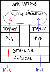
Applications lie mostly on the operating system libraries, which can introduce IPv6 support by adopting the dual stack approach:
- without dual layer: the operating system processes independently IPv4 and IPv6 addresses → the software should be able to manage both IPv4 and IPv6 addresses;
- with dual layer: the operating system is able to convert an IPv4 address into an IPv4-mapped IPv6 address → the software can just support IPv6 addresses without caring of IPv4 addresses.
The variant with dual layer is the most used one because it moves the complexity to the core of the operating system.
Migrating network devices
[edit | edit source]Migrating switches
[edit | edit source]Although in theory switches should be not affected at all by changes at layer 3 because they work up to the layer 2, there could be some troubles with additional functions: for example IGMP snooping, a functionality used to filter incoming multicast packets, needs to look inside the packet → as the packet format and fields change the switch can not recognize the multicast IPv6 packets and it discards them.
Migrating routers
[edit | edit source]Nowadays routers are mostly ready for IPv6, even if performance in IPv6 is still worse than the one in IPv4 because of lack of experience and lower traffic demand.
Tipically routers supporting IPv6 adopt the dual stack 'ships in the night'-like approach: IPv4 and IPv6 are supported by two independent stacks for transport layer → this requires the complete duplication for all components: routing protocols, routing tables, access lists, etc.
Routing tables
[edit | edit source]Routing in IPv6 is performed in the same way as IPv4 but it requires two distinct routing tables, one for IPv4 routes and another for IPv6 routes. IPv6 routing tables can store several types of entries, including:
- indirect entries (O/S codes): they specify the addresses, typically link local, of the interfaces of the next-hop routers to which to send packets addressed towards remote links;
- direct entries: they specify the interfaces of the router itself through which to send packets addressed towards local links:
- connected networks (C code): they specify the prefixes of the local links;
- interface addresses (L code): they specify the interface identifiers in the local links.
Routing protocols
[edit | edit source]Routing protocols supporting IPv6 can adopt two approaches:
- integrated routing (e.g. BGP): the protocol allows to exchange both IPv4 and IPv6 routing information at the same time → IPv4 and IPv6 addresses belonging to the same destination can be transported via a single message → higher efficiency;
- ships in the night (e.g. RIP, OSPF): the protocol allows to exchange only IPv6 routing information → given a destination, a message needs to be exchanged for its IPv4 address and another message for its IPv6 address, and the messages are completely independent of each other → higher flexibility: two different protocols can be used, one for IPv4 routing information and another for IPv6 routing information.
Migrating DNSes
[edit | edit source]DNSes supporting IPv6 can map two IP addresses to the same alias: an IPv4 address and an IPv6 one → a public destination can be reachable via either IPv4 or IPv6.
DNSes supporting IPv6 can return IPv6 addresses not only via IPv6, but also via IPv4: DNS messages in fact belong to the application layer, so the transport layer used to forward the DNS queries and replies does not matter. DNSv6 queries are performed by the following command: set q=aaaa.
A company may decide to offer access to its public website also via IPv6. However, presently most traffic is via IPv4, so generally the service for IPv4 traffic is more reliable in terms of performance and fault tolerance than the one for IPv6 traffic. Therefore the company, especially if it bases its business on its website, does not want the user connecting via IPv6 decides to change to another competitor website because of performance problems. A possible solution is to perform some preliminary assessments to test the performance of the connectivity between the user and the company server, and to implement an additional mechanism into DNSes: they should be able to look at the source address of the DNS query, and return either just the IPv4 address if no assessments have been performed for the connectivity, or both the IPv4 and IPv6 addresses if the performance are good enough.
Tunneling solutions
[edit | edit source]The network will not be IPv6-compatible from day zero → IPv6 traffic may need to traverse IPv4-only network portions. Network-oriented tunneling solutions enable connectivity among IPv6 networks even if they are connected through an IPv4-only infrastructure, and consist in encapsulating the IPv6 packet inside an IPv4 header just for transporting it along the tunnel:

The size for the tunneled packet, including the 20-byte-long IPv4 header, must not exceed the maximum size for IPv4 packets → two solutions are possible:
- fragmentation: the routers should fragment the IPv4 packet before sending it into the tunnel → fragmentation is deprecated due to performance reasons;
- smaller IPv6 packets: the hosts should generate IPv6 packets with a smaller MTU size to take into account the extra-size due to the IPv4 header insertion → routers can specify the allowed MTU size through the 'Router Advertisement' ICMPv6 messages.
Host-oriented tunneling solutions
[edit | edit source]Host-oriented tunneling solutions are more plug-and-play for hosts, but they are not professional solutions and do not solve the problem of IPv4 address shortage because every host still needs to have an IPv4 address. Solutions of this kind are:
- use of IPv6 IPv4-compatible addresses, tunnel termination on host or router;
- 6over4;
- ISATAP.
Use of IPv6 IPv4-compatible addresses
[edit | edit source]They assume that dual-stack hosts, when it is necessary to contact an IPv4 destination, send IPv6 packets to an IPv4-compatible IPv6 address, that is built with the first 96 most significant bits to zero and with the remaining 32 ones coinciding with those of the destination IPv4 address. This IPv6 packet is then encapsulated in an IPv4 packet, whose destination is different depending on whether you want to end the tunnel on the destination host or on a dual-stack router, in particular:
- end-to-end termination: the pseudo-interface on the dual-stack host performs the encapsulation in an IPv4 packet destined for the host to be contacted;
- router dual-stack termination: the pseudo-interface on the host sends the packets destined for a host to the IPv4 address of the dual-stack router, therefore:
- an IPv6 IPv4-compatible address is generated for the destination, as before;
- the IPv6 packet is encapsulated into an IPv4 one destined for the dual-stack router;
- the dual-stack router decapsulates the packet and sends it to the destination host.
6over4
[edit | edit source]The idea is to emulate, through IPv4, a local network that has support for multicast. In practice, as for connecting two IPv6 hosts through the underlying Ethernet network, neighbor discovery is used, relying on the fact that Ethernet has mechanisms for broadcasting, in this solution we reason as if IPv4 was the lower level protocol and we change the neighbor discovery to find IPv4 addresses instead of MAC addresses. This discussion can be generalized to the case in which we want to connect not individual hosts, but clouds of IPv6 networks through dual-stack routers that communicate in an IPv4 network. In this case, in addition to neighbor discovery, a modified version of the router discovery can be used, in order to send a router solicitation to discover the IPv4 addresses of the routers connected to the host's IPv4 network that allow to reach various IPv6 networks; in fact from the router advertisement the host can get information about the IPv6 networks that can be reached from that router.
The problem with this solution is the use of IPv4 multicast, which is usually disabled in networks involving different providers. This solution can be used when you have a whole network under your control: for this reason it cannot be used to migrate the global network from IPv4 to IPv6.
6over4 Neighbor discovery
[edit | edit source]At the proposal of the RFC, IPv6 addresses are mapped to IPv4 addresses: in practice the IPv4 address is used as the interface identifier of the IPv6 address of the destination. This would make the mechanism illustrated so far unnecessary, because the host could tunnel directly, without the need for neighbor discovery to know the IPv4 address. This obviously is not valid when the IPv6 address is not built starting from the IPv4 one, so a more general mechanism is still required to contact a router. Assuming, therefore, to know only one IPv6 address, the neighbor discovery is sent to the solicited node multicast address (for example if the IPv6 address is fe80::101:101 then it is sent to ff02::1:ff01:101) on an IPv4 6over4 multicast network at the address 239.192.x.y, built with the last 16 bits of the IPv6 address (therefore in the previous example it will be 239.192.1.1).
ISATAP
[edit | edit source]The idea is similar to that of 6over4, that is, to use the IPv4 network as a physical link to reach IPv6 destinations, but we want to overcome the limitation of requesting support for multicast. In the absence of neighbor discovery mechanisms, the IPv4 addressing of destinations using ISATAP is incorporated in the IPv6 address, more precisely in the interface identifier, whose format is 0000:5efe:x:y, where x and y are the 32 bits of the IPv4 address. As you can see, this solution does not address the problem for which IPv6 was introduced, that is, the scarcity of IPv4 addresses. However, this solution is more useful in the scenario of an IPv4 link that connects non-hosts, but routers that have IPv6 clouds on the border. In this case a host within the IPv4 network that wants to communicate in IPv6 with a host belonging to a cloud must be equipped with a Potential Router List (PRL). The issues that arise at this point are:
- How to get the PRL?
- Two different solutions exist: the former, which is proprietary, is based on the use of DHCP; the latter, which is standard, is based on the use of DNS. In the latter a DNS Query for a particular name with the format isatap.dominio.it, which will provide the PRL of the IPv6 routers connected to the IPv4 network of the domain specified in the query.
- Which router should the packets for the IPv6 destination be sent to?
- A unicast router discovery is used towards each of the PRL routers, in order to get a reply through a router advertisement. Remember, in fact, that in the advertisement router routers can also announce the list of IPv6 networks that can be reached through them (see the L=0 flag in the Prefix Information Option of the ICMP Router advertisement).
Network-oriented tunneling solutions
[edit | edit source]Typically the network-oriented tunneling solutions require manual configuration, and encapsulation can be based on IPv6 in IPv4 (protocol type = 41), GRE, IPsec, etc.
6to4
[edit | edit source]The biggest step forward from previous solutions comes from the consideration that in the new scenario there is a whole IPv6 network that needs an IPv4 address to get out of the IPv6 cloud, no longer a single host. The mapping between the two addresses is then done in the IPv6 prefix, not in the interface identifier: a special prefix is assigned to all IPv6 networks that includes the IPv4 address assigned to the interface of the dual-stack router that faces the cloud. The prefix 2002::/16 identifies the IPv6 stations which are using 6to4: in the following 32 bits the IPv4 address is set and 16 other ones remain available to represent multiple different subnets, while the interface identifier is obtained as in the other IPv6 use cases. In this solution there is also a router that has a particular role, the 6to4 Relay, which must be the default gateway of the 6to4 routers, in order to forward packets that do not have the 6to4 format just seen to the global IPv6. This router has address 192.88.99.1, which is an anycast address: it was used by who conceived 6to4 because it was considered the scenario in which there are multiple 6to4 Relays in the same network, which would lead to the problem of having to use different addresses. In this way instead, since the anycast address is processed in different ways by routing protocols, you can use the same address and also provide load balancing.
Practical example
[edit | edit source]Let's assume that there are two IPv6 clouds connected to an IPv4 cloud, and that the interfaces of the dual-stack routers have, for the interfaces connected to the IPv6 clouds, the addresses 192.1.2.3 for network A and 9.254.2.252 for network B. Let's also suppose that a host a belonging to network A wants to send a packet to host b belonging to network B. From the configuration outlined and from what has been said it is clear that the hosts existing in network A will have an address of type 2002:c001:02:03/48 and the ones existing in network B 2002:09fe:02fc::/48. The IPv6 packet from a to b will be encapsulated in an IPv4 packet having as destination address 9.254.2.252, obtained from the prefix of the destination IPv6 address: when the packet arrives at that router, it will be decapsulated and forwarded according to the IPv6 addressing plan of the cloud containing network B.
Teredo
[edit | edit source]It is very similar to 6to4, except for the fact that encapsulation is done inside a UDP segment contained in an IPv4 packet, instead of simply being encapsulated in IPv4. This is done to overcome a 6to4 limit, i.e. crossing through NATs: since in 6to4 there is no 2-level segment inside the encapsulating IPv4 packet, the NAT can not work.
Tunnel broker
[edit | edit source]The problem with the 6to4 solution is that it is not generic enough: you are tied to the use of the 2002::/16 addresses and you can not use usual global unicasts. In the tunnel broker solution, since it is no longer possible to deduce from the IPv6 prefix which endpoint the packet should be sent to, a server is used which, given a generic IPv6 address, provides the address of the endpoint tunnel to be contacted. The routers implementing the tunnel broker are called tunnel servers, while the servers providing the mapping are called tunnel broker servers. The tunnels are made as in 6to4, therefore IPv6 inside IPv4: if there was the problem of crossing a NAT you could also think of using Teredo's approach, by encapsulating inside UDP, then inside IPv4.
The tunnel broker server needs to be configured: Tunnel Information Control (TIC) is used to forward information about the networks reachable by a given tunnel server, from the tunnel server being configured to the tunnel broker server. The Tunnel Setup Protocol (TSP) is instead used to request information from the tunnel broker server. Again, you can have a default gateway for the global IPv6 network. In summary, a router with this configuration, when a packet arrives, can:
- forward it directly if it matches with an entry in the routing table (classic situation);
- ask the tunnel broker server to see if it is an address for which tunneling is needed;
- send it to a global IPv6 default gateway if the tunnel broker server response is negative.
Issues
[edit | edit source]- It is a centralized solution and therefore the tunnel broker server is a single point of failure.
- It complicates the control plan.
- If this server is used to interconnect different networks, even belonging to different providers, the problem of responsibility for its management arises.
Advantages
[edit | edit source]- It is more flexible than 6to4, because it allows the use of all global unicast addresses.
Bringing IPv6 support to the network edges
[edit | edit source]NAT-based solutions
[edit | edit source]
The goal is to migrate big provider's networks, so that IPv4 and/or IPv6 clouds at the network edges can use the IPv6 backbone to interoperate. The common scenario is a user who wants to connect to an IPv4 destination through the provider's IPv6 network.
All the available options make use of the NAT. The NAT usage is a bit countercurrent as IPv6 had among its goals the one of avoiding the NAT usage in networks because of several problems brought by NATs (change of packets in transit, problems on peer-to-peer networks, etc.). However the fact that these solutions are based on NATs presents a variety of advantages: NATs are largely spread over networks, their problems and limitations are known, applications which may have problems in going through NATs are known; so in general the advantage is the big experience gained so far.
Major components
[edit | edit source]In NAT-based solutions there are three major components:
- Customer-Premises Equipment (CPE): it is the router at the customer edge just before the provider's network;
- Address Family Transition Router (AFTR): it is an IPv6 Tunnel Concentrator, that is the device at the end of an IPv6 tunnel;
- NAT44/NAT64: it is a NAT for translation from IPv4/IPv6 addresses to IPv4 addresses.
Main NAT-based solutions
[edit | edit source]- NAT64;
- Dual-Stack Lite (DS-Lite): NAT44 + 4-over-6 tunnel;
- Dual-Stack Lite Address+Port (DS-Lite A+P): DS-Lite with preconfigured port ranges;
- NAT444: CGN + CPE NAT44, that is when a home user, which gets the service from the telephone company, adds a NAT in its own home network; every packet outcoming from the home network is subjected to two address translations;
- Carrier Grade NAT (CGN): large-scale NAT44, that is NAT used by telephone companies to map the hundreds of thousands of (users') private addresses into the limited public addresses which are available.
For migration of big networks oriented to mobile devices NAT64 solution is being chosen.
In order to migrate to IPv6 keeping the IPv4 compatibility at the edges of the network some telephone operators are planning massive migrations to DS-Lite because it is a plenty tested solution, and there are several compatible devices already on sale.
The A+P solution is not taken seriously into account yet due to lack of experience.
NAT64
[edit | edit source]
- The IPv6-only user types www.example.com into his browser, and being IPv6 he sends an AAAA query to the provider's DNS64. Let us suppose that www.example.com has the IPv4 address '20.2.2.2'.
- The DNS64, in case it has not the name resolution, needs to send the query to an upper DNS, supposedly in the IPv4 network.
- In the best case the DNS64 sends the AAAA query to the upper DNS and it gets a reply of type AAAA (so IPv6), which it transmits as it is back to the host (it is fully possible to send via an IPv4 packet a DNS query requiring a name resolution into an IPv6 address).
- In the worst case the upper DNS has not IPv4 support, so it replies with a 'Name error'; the DNS64 sends again the query but this time of type A, following which it will gets a proper reply. This reply will be converted into AAAA and transmitted back to the host. In the reply transmitted to the host, the last 32 bits are the same as the ones sent by the upper DNS in the record of type A, while the other 96 bits complete the IPv6 address; therefore the final address will be '64:FF9B::20.2.2.2'.
- Now the host is ready to set up a TCP connection to www.example.com.
- The NAT64 comes into play: it converts the IPv6 packet coming from the host into IPv4, and it performs the reverse operation for packets coming from 20.2.2.2.
Considerations
[edit | edit source]- In such a scenario there is no tunneling: the IPv6 header is just replaced with an IPv4 one and vice versa.
- The IPv6-only host is \ul{not} aware of the fact that the destination address is related to an IPv4 address.
- The NAT64 not only is able to translate IPv6 addresses into IPv4 addresses, but in a certain manner it makes the network believe that 232 IPv6 addresses are available as every packet from the host to the NAT64 will have '64:FF9B::20.2.2.2', with prefix '64:FF9B/96', as a target address.
- The provider's network, the one where the NAT64 and the DNS64 are, is IPv6-native, therefore a host in the provider's network can directly contact another host having IPv6 support without involving the NAT64 at all.
- '64:FF9B/96' is the addressing space specifically standardized for this translation technique, assigned to the NAT64, but the network administrator may decide to change it according to his needs. Note that the network administrator needs to configure the routing so that every packet having that prefix will go to the NAT64, and he needs to configure the NAT64 so that it will translate every IPv6 packet having that prefix into IPv4 and it will forward it into the IPv4 cloud.
Drawbacks
[edit | edit source]- The presence of the NAT introduces a typical issue: the host behind the NAT can not be easily reached from the outside.
- Often it happens that when a DNS has not the address resolution it does not reply at all, instead of sending a 'Name error'; this results in a lengthening of the times due to the waiting for timeout from DNS64, which when the timeout expires sends a query of type A.
- This solution does not work if the user wants to type directly the IPv4 address: the user always needs to specify the name for the destination.
DS-Lite
[edit | edit source]
Dual-Stack Lite (DS-Lite) solution consists in simplifying CPEs by moving the NAT and DHCP functionalities to the edge of the provider's network, so into a device acting as AFTR and as CGN-NAT44.
- The provider's DHCP server assigns an IPv6 address, unique within the provider's network, to each host of each CPE.
- When the user needs to send IPv4 packets a tunneling operation is required, in order to encapsulate IPv4 packets into IPv6 packets as the provider's network is IPv6-only. So, when a CPE receives an IPv4 packet it needs to tunnel it into an IPv6 packet to be able to send it to the AFTR after which there is the IPv4 cloud; therefore the scenario is made up of a lot of tunneling operations in the provider's IPv6 network between the AFTR and one among the several users' CPEs. In particular, the packet between CPE and AFTR will have as a source IPv6 address the AFTR one, and as a target IPv4 address the destination one in the IPv4 network.
- The AFTR, after removing the IPv6 header, sends it to the NAT44 which replaces the IPv4 (private) source address with the IPv4 address to which the NAT will receive packets associated to this flow.
The main advantage for DS-Lite is the one of considerably reducing the number of provider's public addresses.
Can there be any duplicate IPv4 addresses in the provider's network? No, because the NAT44 directly translates the hosts' IPv4 addresses to the available public IPv4 addresses. If there were duplicate private IPv4 addresses the NAT would have ambiguity problems.
Disadvantages
[edit | edit source]- An IPv4 host can not contact an IPv6 destination → IPv6 destinations can be reached just by IPv6 hosts. Instead, an IPv6 host can send and receive packets from IPv6 nodes without going through the provider's AFTR.
- Some kinds of applications can not work in such a situation: the fact that the NAT can not be managed by the user, as it is not on the CPE anymore, makes it impossible to perform some common operations such as opening/closing the ports required for specific applications.
DS-Lite A+P
[edit | edit source]
Dual-Stack Lite Address+Port (DS-Lite A+P) solution consists in still having a provider's IPv6-only network, but the NAT is moved onto the CPE so that the user can configure it according his needs.
Like in DS-Lite, an IPv4 packet outcoming from the CPE is still tunnelized as the provider's network is IPv6-only.
The fact that the NAT on every CPE requires a public IPv4 address is solved by allowing to duplicate public IPv4 addresses, and the CPEs are distinguished based on the port. In fact each CPE uses a specific port range, and the AFTR, knowing the port range used by every CPE, is able to distinguish flows from and to a specific CPE nevertheless there are several CPEs having the same public IPv4 address.
This solution is similar to the DS-Lite one, but the private IPv4 address space is more under the control of the end user, because as the NAT is on the user's CPE the user can configure it, even if with some limitations: he can not open and use ports which are not within his range. This method allows to save IPv4 addresses (but still less with respect to DS-Lite).
This solution in Italy is basically illegal because, as the port number is not recorded, in case of attack it would not be possible to trace back to the attacker.
Transporting IPv6 traffic in the core network
[edit | edit source]The main goal is to have IPv6 traffic over the global network without upsetting the network existing for more than 20 years which at present is working well. It would not be possible to sustain the human and technological costs for worldwide migration to radically change the existing IPv4 network to make it IPv6.
6PE
[edit | edit source]The goal for 6 Provider Edge (6PE) solution is to connect IPv6 clouds one with each other through a MPLS backbone. 6PE requires that the operator's network works by MPLS. In this scenario the provider's edge is represented by the first routers which users' CPEs meet.
Idea
[edit | edit source]- Keeping the network core unchanged (without excluding the possibility for future changes).
- Adding the IPv6 support to the edge of the provider's network.
- Delivering IPv6 routing information via MPLS/BGP, like in VPNs: Computer network technologies and services/VPN#Layer 3: BGP.
Requirements
[edit | edit source]
The primary requirement is to have an MPLS core network.
In the picture:
- the MPLS core network is the one made up of PE-1, P-1, P-2, PE-2;
- the two side devices, PE-1 and PE-2, are partially 'immersed' in the MPLS network;
- links between CE and PE can be thought as links providing an ADSL connection to the home user.
6PE is thought to take a fully-working core network, able to transport IPv4 packets via MPLS, and add the IPv6 support just to the provider's edge routers (PE). In fact, once a packet is encapsulated into an MPLS packet, the intermediate devices will not be interested anymore in the type of contained packet, but they will be interested just in the label which allows them to distinguish the LSP to which to route it.
In fact, on PEs a further update is required in order to add the MG-BGP support, protocol which allows to transport and communicate both IPv4 and IPv6 routes.
Then the big advantage for this solution consists in requiring to update just PEs and not all intermediate routers: after all, an operation that the provider can manage without high costs.
How IPv6 networks are advertised
[edit | edit source]- CE-3 advertises that it is able to reach the IPv6 network '2001:3::/64'.
- This information is received also by PE-2.
- PE-2 sends this information to all the PEs in the network, saying that it is able to reach '2001:3::/64' through the next hop 'FFFF:20.2.2.2', nevertheless its interface is IPv4 (this is because if an IPv6 route is given an IPv6 next hop needs to be given).
- PE-1 receives this information.
- PE-1 sends the received information to all the routers connected to it, so also to the home CEs, saying that it is able to reach the network '2001:3::/64'.
- If an MPLS path between PE-1 and the address '20.2.2.2' does not exist yet, the classical MPLS mechanisms (so the LDPv4 signaling protocol) are used to set up this path.
How IPv6 traffic is routed
[edit | edit source]
To route an IPv6 packet two labels are used:
| LDP/IGPv4 external label to PE-2 | MP-BGP internal label to CE-3 | IPv6 packet to IPv6 destination |
- MP-BGP label (internal): it identifies the destination CE to which the destination PE needs to send the packet;
- LDP/IGPv4 label (external): it identifies the LSP between the two PEs over the MPLS network.
Let us suppose that a host in the network '2001:1::/64' wants to send a packet to a host in network '2001:3::/64':
- the packet arrives at CE-1;
- CE-1 knows that the network '2001:3::1/64' exists and it sends the packet towards PE-1;
- PE-1 puts two labels in front of the packet: the internal label and the external label;
- PE-1 sends the packet to P-1, which sends it to P-2;
- P-2, that is the penultimate hop, removes the external label from the packet (penultimate label popping) and sends it to PE-2;
- PE-2 removes the internal label and sends the packet to CE-3;
- CE-3 forwards the packet to the destination in the network '2001:3::/64'.
Considerations
[edit | edit source]- PE routers have to be dual stack and to support MP-BGP, while intermediate routers do not need any change.
- This solution provides customers with a native IPv6 service without changing the IPv4 MPLS core network (it requires minimal operational costs and risks).
- This solution scales as long as there are few IPv6 clouds to be deployed.
Security issues
[edit | edit source]People have little experience with security problems because IPv6 is not used much yet → IPv6 could still have undiscovered security holes which may be exploited by attackers. Moreover, during the migration phase hosts need to open two ports in parallel, one for IPv4 and another one for IPv6 → two ports have to be protected against attacks from outside.
- DDoS attacks with SYN flooding
A host interface can have multiple IPv6 addresses → it can generate multiple TCP SYN requests, each one with a different source address, to a server in order to saturate its memory by making it open several unclosed TCP connections.
- Fake Router Advertisement messages
A host may start sending 'Router Advertisement' messages advertising fake prefixes → the other hosts in the link will start to send packets with wrong prefixes in their source addresses.
VPN
A company that wants to build a corporate private network for its remote terminals (single users, data-centers, branches) can adopt two different approaches:
- the company can build its own dedicated infrastructure (leased line, dial-up connection);
- the company can adopt a VPN solution.
A Virtual Private Network (VPN) allows a company to deploy connectivity to multiple users over a public shared infrastructure (the Internet or an Internet Service Provider's network) enforcing its own policies (such as security, quality of service, private addressing) as if it was its own private network.
The advantages of a VPN solution are:
- cheapness: expensive physical connections up to the remote users have not to be built anymore, but the VPN solution exploits a pre-existing infrastructure so that the cost is shared;
- selectivity: thanks to a firewall only the users having the rights can access → greater security;
- flexibility: allowed users can easily be added, and users can easily move.
A VPN is made up of some main components:
- data are delivered through tunnels, so they are separated by other data moving around over the shared infrastructure, by using protocols such as GRE, L2TP, MPLS, PPTP and IPsec;
- data are encrypted for a greater security, by using protocols such as IPsec and MPPE;
- data are checked for integrity, so they can not be tampered, thanks to TCP checksum or AH in IPsec;
- before a tunnel is set up, the identity of who is on the other side of the tunnel is checked through authentication mechanisms (for example by using digital certificates).
Classification
[edit | edit source]
VPN solutions can be classified according to:
- deployment: access or site-to-site (intranet/extranet);
- internet access: centralized or distributed;
- model: overlay or peer;
- provision: customer or provider;
- layer: layer 2, layer 3 or layer 4;
- virtual topology: hub and spoke or mesh.
| overlay | peer | |
|---|---|---|
| access | L2TP, PPTP | |
| site-to-site | IPsec, GRE | MPLS |
Deployment scenarios
[edit | edit source]VPNs can be deployed in two main scenarios:
- access VPN (also called 'remote VPN' or 'virtual dial in'): it virtualizes dial-up connection and connects a single user to a corporate network through ISDN, PSTN, cable modem, wireless LAN by using protocols such as PPTP and L2TP;
- site-to-site VPN: it virtualizes leased line and connects multiple remote networks one to each other by using protocols such as IPsec, GRE and MPLS.
- Site-to-site VPNs can be deployed in two ways:
- intranet VPN: all the interconnected networks belong to the same company;
- extranet VPN: the interconnected networks belong to multiple companies.
VPN features must meet some requirements:
- security: a firewall can restrict access to network resources;
- data encryption: in order to protect information transmitted over the shared infrastructure;
- reliability: mission critical traffic has to be guaranteed to arrive at the destination;
- scalability: the solution must work for both small and large networks;
- incremental deployment: the solution keeps working as the network grows;
- additional requirements for access VPNs:
- strong authentication: in order to verify mobile users' identities (e.g. a personal notebook may be stolen);
- centralized management of users and their accounts;
- additional requirements for site-to-site extranet VPNs:
- selected access: each company can give other companies the access to some services but prevent the access to other services of its private network;
- address clash management: a private address may belong to two different private networks → a NAT is required;
- use of an open, standard-based solution: different companies need to be able to share the same VPN solution;
- traffic control: each company needs to control the amount of traffic coming in from the other company networks and to eliminate bottlenecks at network access points.
Internet access
[edit | edit source]A remote terminal connected to a VPN can access the public Internet in two ways:
- centralized internet access: all the traffic towards and from the Internet always passes through the headquarters VPN gateway;
- distributed internet access: the traffic towards and from the Internet does not involve the VPN, which is deployed only for corporate traffic.
Centralized internet access
[edit | edit source]- Advantages
- centralized policy management: a company can set its own policies for internet access (e.g. forbidding employees to access certain websites while they are working) once for all the connected remote terminals;
- security benefit: the corporate firewall can protect hosts against malicious packets coming from the Internet.
- Disadvantages
- lower speed at remote terminals: the packets towards and from the Internet have to travel for a higher number of hops because they always have to pass through the headquarters VPN gateway instead of heading directly towards the destination;
- higher bandwidth required at headquarters;
- compulsory connection: the VPN must be always active, that is the user must not be able to temporarily disable the VPN and surf the Internet without the corporate firewall protection, otherwise if he gets infected when he goes back to the VPN he will infect the corporate network because the traffic coming from him is not firewalled.
Distributed internet access
[edit | edit source]- Advantages
- higher speed at remote terminals: the packets always head directly towards the Internet destination;
- voluntary connection: the user can disable the VPN any time without additional security threats.
- Disadvantages
- distributed policy management: the company needs to configure multiple routers at the remote terminals in order to set its own policies;
- security threat: the corporate firewall protection is missing.
Models
[edit | edit source]-
 Overlay model.
 -
 Peer model.


VPNs can be split into two models according to the role of the shared infrastructure:
- overlay model: the infrastructure is unaware of the VPN solution and offers just the IP connectivity service: it just carries packets, without knowing that they are VPN packets, between VPN gateways that don't interact with the infrastructure → good for data privacy: the manager of the infrastructure can not look at private data or he can not leverage routing information;
- peer model: the gateways inside the infrastructure participate to the creation of the VPN and interact among themselves → better routing, more scalability.
- Non-MPLS-based peer-model VPNs can be:
- dedicated router: the manager of the infrastructure dedicates some routers altogether to a customer, some other ones altogether to another customer, and so on;
- shared router: each router in the infrastructure is shared among multiple customers → lower cost.
Provision
[edit | edit source]-
 Provider provision.
 -
 Customer provision.


VPNs can be customer or provider provisioned:
- customer provision: the user creates and manages the VPN by himself, and tunnels are set up between Customer Edges (CE);
- provider provision: the VPN is provided and managed altogether by the provider of internet connectivity, and tunnels are set up between Provider Edges (PE).
The customer provisioned VPNs can not be peer-model because the provider can not be aware of a VPN self-created by the customer.
Layers
[edit | edit source]VPN connectivity can be at different layers:
- layer 2: Ethernet frames are exchanged in the VPN:
- Virtual Private LAN Service (VPLS): it virtualizes a LAN: terminals are connected as if they were in the same LAN → broadcast packets are allowed;
- Virtual Private Wire Service (VPWS): it virtualizes a leased line (over a packet-switching network);
- IP-only LAN-like Service (IPLS): it virtualizes an IP network, but only IP (ICMP and ARP) packets are allowed;
- layer 3: IP packets are exchanged in the VPN;
- layer 4: TCP connections (possibly with SSL for security) are set up in the VPN.
Virtual topologies
[edit | edit source]VPNs can be split into two categories according to their virtual topology:
- hub and spoke: each pair of terminals can communicate to each other only by going through the headquarters → a bottleneck may occur at the headquarters due to the higher traffic;
- mesh: each pair of terminals can communicate to each other directly without going through the headquarters → routing is better, but the number of tunnels is higher.
Protocols
[edit | edit source]PPP
[edit | edit source]Point-to-Point Protocol (PPP) is a layer 2 protocol used in point-to-point connections (dial-up, ISDN) to encapsulate any protocol at upper layers. It is an extension to HDLC.
A PPP packet has the following format:
| 1 byte | 1 byte | 1 byte | 1 or 2 bytes | 2 or 4 bytes | 1 byte | |
| 01111110 (flag) | Address | Control | Protocol | Data | CRC | 01111110 (flag) |
where the most significant fields are:
- leading and trailing flags: they are required for data framing;
- Address and Control fields: they are inherited from HDLC but they are completely meaningless in point-to-point connections; they were kept to make it simple to upgrade the processing algorithms in HDLC devices;
- Protocol field: it specifies the protocol at upper layer for the encapsulated packet.
'01111110' is the sequence delimiting the frame, but in order to send that sequence as data some stuffing rules are required. In PPP stuffing is at byte level: the escape sequence '01111101' is inserted both when a byte equal to the delimiting byte appears in the data, and when a byte equal to the escape byte itself appears:

Link Control Protocol (LCP) has the task of opening and closing PPP connections, negotiating some options (such as frame maximum length, authentication protocol).
GRE
[edit | edit source]An IP packet can not encapsulate directly a protocol at layer 3 or lower, because the 'Protocol' field in the IPv4 header can specify only protocols at upper layers (such as TCP, UDP, ICMP).
Generic Routing Encapsulation (GRE) is a protocol to encapsulate any protocol (including IP and other protocols at lower layers) into IP: the GRE header is inserted between the encapsulating IP header and the encapsulated packet, and the 'Protocol' field in the encapsulating IP header is set to 47.
The GRE header has the following format:
| 5 | 8 | 13 | 16 | 32 | ||||
| C | R | K | S | s | Recur | Flags | Version (0) | Protocol type |
| Checksum (optional) | Offset (optional) | |||||||
| Key (optional) | ||||||||
| Sequence number (optional) | ||||||||
| Routing (optional) ::: | ||||||||
where the most significant fields are:
- C, R, K, S flags (1 bit each one): they indicate the presence/absence of optional fields;
- strict source routing (s) flag (1 bit): if set to 1, the packet is dropped if, when the source route list ('Routing' field) ends, the destination has not been reached yet (similar to TTL);
- Recur field (3 bits): it specifies the allowed maximum number of additional encapsulations (currently not supported);
- Version field (3 bits): it specifies the version of the GRE protocol (0 in this case);
- Protocol type field (16 bits): it specifies the protocol of the encapsulated packet;
- Routing field: it specifies a sequence of IP addresses corresponding to the intermediate routers the packet should go through (source routing).
- The 'Routing' field is in turn made up of some fields (besides the list of IP addresses), including:
- Address family field: it specifies the kind of addresses in the list (IP in this case);
- SRE Offset field: it is a pointer to the list item containing the IP address of the current next hop, updated on each source route hop;
- SRE Length field: it specifies the length of the list (in bytes).
Enhanced GRE
[edit | edit source]The format of the Enhanced GRE header introduces the new 'Acknowledgment number' field:
| 5 | 8 | 13 | 16 | 32 | |||||
| C | R | K | S | s | Recur | A | Flags | Version (1) | Protocol type |
| Key (payload length) | Key (call ID) | ||||||||
| Sequence number (optional) | |||||||||
| Acknowledgment number (optional) | |||||||||
where the most significant fields are:
- Key field (32 bits):
- payload length (16 bits): it specifies the packet length excluding the GRE header (in bytes);
- call ID (16 bits): it specifies the session ID for the packet;
- Acknowledgment number field (32 bits): the sender puts in the packet the last packet sequence number it has received from the destination (cumulative ACK).
- The new 'Acknowledgment number' field, in combination with the 'Sequence number' field, allows some additional mechanisms:
- flow control: sliding windows avoid destination flooding, and they are moved when ACK packets are received;
- out-of-order packet detection: Enhanced GRE was designed for PPP encapsulation, and PPP is a protocol for point-to-point connections where it is not expected packets arrive out-of-order → out-of-order packets are always discarded;
- lost packet detection: when a timeout expires, that is no ACKs have been received, the packet is detected as lost, but the detected lost packets are not re-transmitted;
- congestion control: when too many timeouts are detected, the packet transmission is slowed down not to congest the network.
L2TP
[edit | edit source]
Layer 2 Tunneling Protocol (L2TP) is a protocol to tunnel any layer 2 protocol (PPP in this discussion) into IP. L2TP was originally designed for provider provisioned access VPNs and it was standardized by IETF; later it was extended to customer provisioned access VPNs by simply implementing the LAC functionality into the user machine.
In the L2TP original reference scenario, a remote user wants to send a packet through a point-to-point (PPP) connection to an internal server inside the corporate network. An L2TP tunnel to the target L2TP Network Server (LNS) and an L2TP session inside the tunnel are required to emulate the PPP connection over the service provider network.
When the PPP frame arrives at the L2TP Access Concentrator (LAC), if an L2TP tunnel has not been established yet to the LNS, before opening an L2TP session the LAC has to establish a tunnel to the LNS: the LNS authenticates itself to the LAC by using a challenge-based mechanism similar to Challenge Handshake Authentication Protocol (CHAP), and a new control connection is created.
Each L2TP session uses two channels inside the tunnel:
- data channel: to carry data messages, that is the PPP frames;
- control channel: to exchange control messages, aimed to manage the communication (such as verifying that packets arrive, retransmitting lost packets, checking the right order of packets).
- In contrast to data messages, control messages are exchanged in a reliable way: lost control messages are always retransmitted.
Multiple sessions may coexist within the same tunnel, sharing the same control connection, to distinguish multiple flows of PPP frames from multiple remote users: each tunnel is identified by a tunnel ID, each session is identified by a session ID.
- Security
Besides the authentication ensured during the tunnel establishing step, L2TP does not provide any security mechanism by itself: in fact it does not make sense to use mechanisms like encryption for L2TP packets travelling along the tunnel, because the service provider's LAC still can look at the layer 2 frames → any security mechanism has to be implemented end-to-end, that is between the user and the final destination inside the corporate network.
Optionally it is possible to use IPsec through the tunnel: it provides a strong security, but it is complicated to be implemented.
A packet inside the L2TP tunnel includes several encapsulated headers:
| MAC header | IP header | UDP header | L2TP header | PPP header | PPP payload |
- PPP header
It identifies the point-to-point connection between the remote user and the internal server inside the corporate network.
- L2TP header
It identifies the L2TP tunnel:
| 8 | 16 | 32 | |||||||
| T | L | 0 | S | 0 | O | P | 0 | Version (2) | Length |
| Tunnel ID | Session ID | ||||||||
| Ns | Nr | ||||||||
| Offset size | Offset pad ::: | ||||||||
where the most significant fields are:
- T flag (1 bit): if set to 0 the packet is a data message, if set to 1 it is a control message;
- Tunnel ID field (16 bits): it identifies the L2TP tunnel;
- Session ID field (16 bits): it identifies the L2TP session, that is the data channel in the tunnel;
- Ns field (16 bits): it contains the sequence number of the data/control message;
- Nr field (16 bits): it contains the sequence number of the next control message to be received for a reliable control connection.
- UDP header
Why is a layer 4 protocol such as UDP used to move layer 2 frames? This can be explained by considering firewalls over a general network: if a packet does not contain a layer 4 encapsulation, it is easier to get discarded by firewalls.
Another possible reason is that layer 4 can be accessed through sockets, while the operating system is in charge of layer 3. Since L2TP wants to be a solution against PPTP (proposed by operating system vendors), L2TP designers wanted to make it accessible to the applications and not to be tight to the will of the operating system vendors.
It is also possible to use a different layer 4 protocol (such as ATM, Frame Relay).
- IP header
It contains the IP addresses of the tunnel endpoints.
In the original reference scenario, the IP addresses correspond to the LAC and the LNS.
PPTP
[edit | edit source]
Point-to-Point Tunneling Protocol (PPTP) is a protocol to tunnel the PPP protocol into IP. PPTP was originally designed for customer provisioned access VPNs and it was developed by major operating system vendors; later it was extended to provider provisioned access VPNs by introducing a PPTP Access Concentrator (PAC) with functionality similar to the LAC one.
The PPTP original reference scenario differentiates itself from the L2TP one for the fact that the PPTP tunnel is established between the remote user itself and the PPTP Network Server (PNS).
In contrast to L2TP, PPTP provides weak (optional) security mechanisms: the standard covers the usage of specific Microsoft-proprietary security protocols such as MPPE for encryption and MS CHAP for authentication, so there is not any negotiation of protocols.
Data channel
[edit | edit source]The encapsulated PPP frames go through the data channel:
| IP header | GRE header | PPP header | PPP payload |
PPTP uses the Enhanced GRE protocol to encapsulate the PPP frames into IP. The PPP payload can be optionally encrypted by MPPE.
Control channel
[edit | edit source]The PPTP control messages go through the control channel:
| IP header | TCP header | PPTP control message |
Control messages are required for tunnel data session setup, management and tear-down, and they are sent to the well-known TCP port 1723 of the PNS.
IPsec
[edit | edit source]The functionality of the Internet Protocol Security (IPsec) protocol suite in IPv4 is very similar to the one in IPv6: ![]() Computer network technologies and services/IPv6#IPsec.
Computer network technologies and services/IPv6#IPsec.
The main difference is that in IPv6 IPsec is an extension header included in the standard, while in IPv4 it is a new additional protocol encapsulated into IP (for AH the 'Protocol' field is set to 51, for ESP it is set to 50):
| IPv4 header | AH header | TCP/UDP header | payload |
| authenticated data | |||
| IPv4 header | ESP header (for encryption) |
TCP/UDP header | payload | ESP header |
| encrypted data | ||||
| authenticated data | ||||
SSL
[edit | edit source]Secure Sockets Layer (SSL), today called Transport Layer Security (TLS), is a cryptographic protocol which is designed to provide communication security between a client and a server:
- the client opens a TCP connection on port 443 with the server, and sends a challenge for server authentication;
- the server sends to the client a Hello message containing its certificate and the response to the challenge encrypted by the server's private key;
- the client verifies the certificate by looking into a list of certificates given by a trusty certification authority, then it decrypts the response to the challenge by using the server's public key;
- the client decides a private key for the secure communication and sends it to the server by encrypting it through the server's public key → from this point on all record messages will be encrypted by using that private key (which should be periodically renegotiated);
- often the server asks the user to type its username and password on a web page for client authentication (at application layer).
Access VPNs
[edit | edit source]Dial-up connection scenario
[edit | edit source]
Basically a remote user, typically an employee of a company, wants to contact a server going through the corporate network. He can establish a dial-up point-to-point connection to the corporate gateway using PPP to encapsulate the IP packets:
- through Link Control Protocol (LCP) he can negotiate the layer 2 parameters (such as the authentication protocol);
- through Network Control Protocol (NCP) he can negotiate the layer 3 parameters (such as the private IP address within the corporate network, the DNS).
Before accepting the dial-up connection, the corporate gateway checks the user by contacting the corporate security server through the Remote Authentication Dial In User Service (RADIUS) protocol. The corporate security server is a centralized AAA server:
- Authentication: identifying the user (e.g. through user name and password);
- Authorization: checking which services the user can access and which ones are restricted to the user;
- Accounting: keeping track of the user activity (e.g. for billing).
Access VPNs can virtualize dial-up connections between a remote user and the corporate network over the service provider shared infrastructure to reduce costs. PPP protocol will keep being used encapsulated in VPN tunnels, avoiding to change too much the corporate gateway.
Customer provision
[edit | edit source]
In customer provisioned access VPNs, the tunnel is established between the remote user and the corporate gateway:
- the user requests to establish a PPP dial-up connection to the service provider NAS, asking for negotiating the configuration parameters for the connection through LCP and NCP;
- the NAS checks the user identity through the provider security server by using the RADIUS protocol;
- the NAS provides the user with the configuration parameters for the PPP dial-up connection, in particular the public IP address;
- the user requests to open a VPN tunnel with the corporate gateway, by sending a PPP frame containing an IP packet whose destination IP address is the public IP address of the corporate gateway;
- the NAS forwards the request over the service provider network to the corporate gateway;
- the corporate gateway checks the user identity through the corporate security server by using the RADIUS protocol;
- the corporate gateway provides the user with the configuration parameters for the VPN tunnel, in particular the private IP address within the corporate network;
- the NAS forwards the corporate gateway reply to the remote user.
Once the VPN is set up, the user has got two IP addresses: a public one for the service provider NAS and a corporate one for the corporate gateway. The PPP frames the user can send through the tunnel have the following format:
| PPP header | IP header | PPP header | IP header | IP payload | ||
| src: | public IP address of the user | src: | corporate IP address of the user | |||
| dst: | public IP address of the corporate gateway | dst: | corporate/public IP address of the final destination | |||
- Advantage
The user is independent of the service provider: the latter in fact provides the user with just the internet connection to the corporate gateway.
- Disadvantage
The user may temporarily disable the VPN connection and connect to an external server over the Internet → if he gets a malware, when he goes back to the VPN he will infect the corporate network.
Provider provision
[edit | edit source]
In provider provisioned access VPNs, the tunnel is established between the service provider NAS and the corporate gateway:
- the user requests to establish a PPP dial-up connection to the corporate gateway, asking for negotiating the configuration parameters for the connection through LCP and NCP;
- the NAS checks the user identity through the provider security server by using the RADIUS protocol, in particular identifying the user as a VPN user;
- the NAS requests to open a VPN tunnel, related to the user, with the corporate gateway, by sending an IP packet whose destination IP address is the public IP address of the corporate gateway;
- the corporate gateway checks the user identity through the corporate security server by using the RADIUS protocol;
- the corporate gateway provides the NAS with the configuration parameters for the VPN tunnel;
- the NAS optionally logs the acceptance and/or the traffic to charge the company for the service;
- the corporate gateway provides the user with the configuration parameters for the PPP connection (dial-up is virtualized), in particular the private IP address within the corporate network;
- the NAS forwards the corporate gateway reply to the remote user.
Once the VPN is set up, the user has got only the corporate IP address, unaware of the tunnel between the service provider NAS and the corporate gateway. The IP packets the NAS can send through the tunnel have the following format:
| IP header | PPP header | IP header | IP payload | ||
| src: | public IP address of the service provider NAS | src: | corporate IP address of the user | ||
| dst: | public IP address of the corporate gateway | dst: | corporate/public IP address of the final destination | ||
- Advantage
The user can not access the Internet without going through the corporate gateway (centralized access) → greater security.
- Disadvantage
The user is not independent of the service provider: in fact if he changes service provider the VPN connection will not work anymore.
Site-to-site VPNs
[edit | edit source]IPsec-based VPNs
[edit | edit source]In IPsec-based VPNs, IPsec is used in tunnel mode between the VPN gateways: the IP packet between two hosts is encapsulated into an IP packet, having the ESP header (and optionally the AH header), between the two VPN gateways, so that also the IP addresses of the two hosts can be encrypted by ESP.
The private intranet can be protected by:
- a firewall: it filters the traffic according to the corporate policies about for example the allowed IP addresses, and it can be put at different locations in relation to the VPN gateway:
- before the VPN gateway: the VPN gateway is protected, but the firewall can not filter the VPN traffic because it is encrypted;
- after the VPN gateway: the firewall can filter the decrypted VPN traffic, but the VPN gateway is not protected;
- in parallel with the VPN gateway: the packets go through the firewall both before and after the VPN gateway, so the VPN gateway is protected and the VPN traffic is filtered, but the workload for the firewall is higher;
- integrated into the VPN gateway: both the functionalities of VPN gateway and firewall are integrated into a single device → maximum flexibility;
- an Intrusion Detection System (IDS): it observes the traffic trying to detect whether there are attacks going on, and two IDS probes are put in parallel with the VPN gateway:
- the probe before the VPN gateway observes the traffic coming from the tunnel and protects from attacks coming from the shared infrastructure;
- the probe after the VPN gateway observes the VPN traffic and protects from attacks coming from the corporate network (e.g. malware installed on employee PCs, attacks from another company if the site-to-site VPN is extranet).
The presence of NATs may cause problems with IPsec:
- AH authenticates the whole packet, so it also covers the IP header → NATs need to change IP addresses, so authentication will no longer work;
- ESP encrypts the payload, so NATs located along the tunnel will not be able to see encrypted IP addresses and TCP/UDP ports to deal with different VPN sites.
MPLS-based VPNs
[edit | edit source]Layer 2: PWE3
[edit | edit source]
The Pseudo Wire Emulation End-to-End (PWE3) standard allows to emulate wires over an MPLS network to exchange Ethernet frames between layer 2 terminals such as Ethernet switches or phone switches.[1] This type of connection requires some requirements in terms of constant delays of Ethernet frames like they traveled over a physical wire.
Traffic is carried through an LSP, then it needs to be able to go to one of multiple sites connected to different interfaces of the ingress/egress LSR:
- external label: it identifies the LSP between two ingress/egress LSRs, and it is followed by one of multiple internal labels;
- internal label: it identifies the VPN tunnel for a company, and the ingress/egress LSR uses it to send the frame out of one of its interfaces towards the site of the company.
MPLS-based layer 2 VPNs do not take advantage of all MPLS benefits, because routing protocols for traffic engineering work very well with IP → usually LSPs are configured manually.
Layer 3: BGP
[edit | edit source]
Border Gateway Protocol (BGP) was extended to internal BGP and external BGP to support the deployment of VPNs over MPLS, for example for company A's site 1:
- company A's CE1 advertises to PE1 the destinations within the site 1, that is it tells PE1 all the IP addresses that can be reached within the site 1, through the internal BGP;
- PE1 assigns a label to each IP address from CE1 and it records the mapping into a VPN Routing and Forwarding (VRF) table specific for its port towards CE1;
- PE1 advertises the chosen labels to the other PEs through the external BGP by sending packets containing each one an IP address plus a route distinguisher identifying the address family, that actually is the port towards the company A's site, useful in case there are two identical private addresses in two different corporate networks.
This step needs to be performed manually: the system administrator has to open a peering session between PE1 and each one of the other PEs in the MPLS network; - the other PEs can either process the advertisement messages or ignore them:
- each other PE which one of company A's sites is connected to (in the picture PE3) records into its VRF table the advertisement information from PE1, that is the chosen label for each IP destination within the site 1, in other words IP addresses associated to the site 1's address family, plus PE1's IP address;
- each other PE which no company A's sites are connected to (in the picture PE2) just ignores the advertisement information from PE1;
Once the IP destinations have been advertised among the PEs, VPN data can begin to be sent along the MPLS LSPs, for instance from company A's CE3 to company A's CE1:
- PE3, that is the ingress LSR, pushes two labels into the label stack:
- internal label: the one previously advertised by PE1;
- external label: the one decided by LSRs through MPLS label binding, distribution and mapping protocols for the LSP from PE3 to PE1;
- intermediate LSRs do not care about the internal label, but they operate just on the external label along the LSP;
- the last LSR just before PE1 strips off the external label (penultimate label popping) and it sends the packet to PE1;
- PE1, that is the egress LSR, searches its VRF tables for the internal label and it finds the port where to send the packet out, then it strips off also the internal label and it sends the packet to CE1.
- Advantage
This solution is very scalable:
- each intermediate LSR has to deal with as many LSPs as PEs are, not as many LSPs as IP destinations are;
- each PE has to deal with as many VRF tables as the sites connected to it are.
- Disadvantage
The peering sessions between the PEs are to be configured manually.
This solution does not provide any cryptography because it is provider provisioned and the company needs to trust the service provider.
Layer 3: virtual router
[edit | edit source]
In MPLS-based VPNs with virtual routers, each PE runs a (virtual) router instance for each company which is connected to it, so that every instance has to deal with just one corporate network → the protocol is simpler because it has to deal with just one VPN at a time, but scalability is lower because the router instances need to be configured manually.
SSL (pseudo)VPNs
[edit | edit source]SSL can be used to create site-to-site and access VPNs, but it is mostly used in SSL (pseudo)VPNs to grant a secure access to services (such as web service, e-mail) through TCP/UDP-based tunneling. The main advantage for SSL (pseudo)VPNs is that they have a good chance of working on any network scenario, without any problems in traversing NATs, firewalls or routers, and SSL services can also be accessed by web browsers through HTTPS.
Comparison to alternative solutions
[edit | edit source]Comparison to IPsec
[edit | edit source]- Advantages
SSL is more convenient than IPsec in terms of:
- usage: IPsec has too many options to be configured and administered, while SSL just requires to compile the application along a library implementing SSL;
- security: it works at application layer → an attack to SSL just involves the application and not the whole operating system;
- maturity: it has been used for a lot of years over a lot of versions → few bugs in code;
- compatibility with NAT traversal:
- no authentication of IP header because SSL is on top of the transport layer;
- no encryption of ports as with IPsec ESP.
- Disadvantage
SSL is critical with DoS attacks: packets always need to be processed up to transport layer, while in IPsec they are dropped already at network layer.
Comparison to PPTP
[edit | edit source]SSL overcomes some PPTP issues:
- poor interoperability with non-Microsoft platforms;
- some network administrators may configure their routers to block GRE, on which PPTP is based, due to the fact that they do not like source routing feature.
SSL (pseudo)VPN flavors
[edit | edit source]- Web proxying
The web server does not support HTTPS → a 'VPN gateway',[2] at the edge of the corporate network, downloads web pages from the web server through HTTP, and ships them to the user, outside the corporate network, through HTTPS.
- Port forwarding
The client runs an application supporting an application protocol (such as FTP, SMTP, POP3) → a port forwarder installed on the client converts packets, sent to a specific port, from the application protocol into HTTPS packets sending them from another port, and vice versa.
- Application translation
The web server is an application server (e.g. mail server) supporting an application protocol (such as FTP, SMTP, POP3) → the 'VPN gateway' converts HTTPS into the application protocol and vice versa through a port forwarding mechanism implemented inside the 'VPN gateway'.
- SSL'ed protocols
Some application protocols can natively integrate SSL into themselves (e.g. SMTP-over-SSL, POP-over-SSL) → client and web server can directly communicate in a secure way without the need for translation by a 'VPN gateway'.
- Application proxying
The client uses a SSL'ed protocol, but the web server does not support it → a 'VPN gateway' is still required with port forwarding mechanism.
- Network extension
Both the client and the web server do not support SSL → two 'VPN gateways' are required, one at the user side and the other one at the web server side, so the SSL tunnel is created between the two 'VPN gateways'.[3]
References
[edit | edit source]- ↑ It is also possible to use routers as terminals, but it makes very few sense.
- ↑ This is a loose definition of VPN gateway: indeed it would be more accurate to define it as a proxy.
- ↑ This is not a SSL (pseudo)VPN.
VoIP
Voice over IP (VoIP) is the set of technologies to carry voice calls, along with multimedia data, over IP networks.
Circuit switching versus packet switching
[edit | edit source]Circuit-switching telephone network
[edit | edit source]In the traditional circuit-switching telephone network (POTS), voice is carried through allocation of static circuits where voice is sampled at a bit rate of 64 Kbps (according to the sampling theorem). By using such a network there are some limitations:
- no compression: it wouldn't make sense to save bits as 64 kilobits per second are statically allocated for each phone call;
- an integer number of circuits must be allocated in order to support multimedia or multi-channel communication;
- no silence suppression: voice samples are transmitted also during pauses and circuits keep being allocated;
- no statistical multiplexing: it is not possible to dynamically share bandwidth among multiple calls according their current needs;
- signaling procedure (ring tone, busy tone, idle tone, etc.) is required for circuit allocation.
Packet-switching data network
[edit | edit source]In a packet-switching data network (IP), voice is dynamically carried via packets, and this enables new features:
- better compression for a smaller number of packets;
- high-quality communication: the bit rate is not limited to 64 Kbps anymore;
- silence suppression: no packets are transmitted during pauses;
- statistical multiplexing: bandwidth allocation is flexible;
- signaling procedure does not allocate static resources anymore;
- nomadicity: the user can be reachable through the same phone number or account when he moves.
However a new problem is introduced: resources can not be really reserved in a packet-switching network → it is very difficult to grant quality of service for voice calls because packets may arrive with some delays or may be lost:
- delays: some reference values for end-to-end delays have been defined by ITU:
- 0-150 ms: this is acceptable for human ear;
- 150-400 ms: this is acceptable only for inter-continental calls;
- > 400 ms: this is not acceptable and it harms conversation;
- losses: the human ear can tolerate without problems at most 5% missing packets.
- TCP or UDP?
UDP and TCP packets arrive (theoretically) at the receiver at the same time; the only difference is that TCP has to wait for the acknowledge packets → UDP would be the most natural choice. Indeed Skype often uses TCP because it is simpler to go through NATs and firewalls even if sometimes there may occur small silences due to sliding-window mechanisms.
Migration from circuit switching to packet switching
[edit | edit source]The traditional circuit-switching network (POTS) can be migrated to a IP-based packet-switching network in a gradual way:
- Telephone over IP (ToIP)-based network: terminals at network edges still work in a circuit-switching way, but the network backbone is based on IP and performs internally packetization → as VoIP usage is hidden from the user additional multimedia services are not available to the end user.
New telecom operators can build their phone networks as ToIP-based networks → telecom operators can save money by building and maintaining a single integrated infrastructure; - mixed network: some terminals are VoIP, other ones are still traditional;
- IP network: all terminals are VoIP, but intelligent network services (e.g. toll-free numbers) are still traditional, because they work so well that network operators are reluctant to modernize them;
- IP-only network: all terminals are VoIP and all intelligent network services work over IP.
Gateway
[edit | edit source]
The gateway is a device which allows to connect a POTS network with an IP network. It is made up of three components:
- media gateway: it is able to convert voice samples from the POTS network into data packets to the IP network and vice versa;
- signaling gateway: it is able to convert signaling tones from the POTS network into signaling packets to the IP network and vice versa;[1]
- gateway controller: it is in charge of supervising and monitoring the whole gateway, by controlling traffic quality, by performing authorization, by performing authentication (for billing), by locating destinations, and so on.
- The gateway controller alone is still useful in IP-only networks.
Steps for VoIP flow creation
[edit | edit source]At the transmitter side
[edit | edit source]The receiver should perform the following steps:
- sampling
- encoding
- packetization
- queuing
- transmission
Sampling
[edit | edit source]Sampling allows to convert voice from an analogue signal to digital samples. Sampling is characterized by sensibility (bit), sampling frequency (hertz = 1/s), and theoretical bit rate (bit/s).
Encoding
[edit | edit source]Encoding techniques allow to reduce the bit rate, but they may introduce additional delays due to encoding algorithms.
Main encoding techniques are:
- differential encoding: each sample is encoded based on differences with respect to the previous sample and/or the following sample;
- weighted encoding: during a video call the interlocutor figure should be encoded at a higher bit rate with respect to the surrounding environment;
- lossy encoding: some audio and video information are irreversibly removed (possibly the quality loss should not be perceived by human senses).
Complexity is an important issue when encoding algorithms have to be executed on mobile terminals (such as embedded systems or not very performing low-power devices). Moreover some services do not support data encoded by lossy compression: for example, a fax does not support quality loss. That is why telecom operators still prefer to use PCM64 codec with a constant bit rate of 64 Kbps: it requires few power for processing and it is supported also by faxes and other services using the telephone network.
The speaker's voice, after exiting the receiver loudspeaker, may come back through the receiver microphone arriving at the transmitter loudspeaker after a delay called round trip delay which if significant it may disturb the speaker himself → echo cancellation is thought to avoid the speaker to hear his own voice.
Packetization
[edit | edit source]Packetization delay depends on the number of samples inserted into each packet, that is a trade-off between delay and efficiency:
- delay: if too many samples are put in a single packet, the packet should wait for the last sample before being sent → if too many samples are packetized together, the first sample will arrive with an important delay;
- efficiency: every IP packet has an overhead in size due to its headers → if too few samples are packetized together, the bit rate will significantly increase due to header overhead.
Some redundancy-based error correction techniques may be contemplated: each packet carries also the previous sample along the new sample, so if the previous packet is lost it will be still possible to recover its sample.
Queuing
[edit | edit source]When input traffic exceeds the output link capacity, the router should store packets waiting for transmission (buffering) → this increases delay and jitter. Priority queue management addresses these issues: ![]() Computer network technologies and services/Quality of service.
Computer network technologies and services/Quality of service.
Transmission
[edit | edit source]In order to reduce transmission delays there are some possible solutions:
- increasing the bandwidth, but ADSL providers usually are more interested in increasing just the downstream bandwidth;
- using PPP interleaving, that is splitting a large frame into several smaller PPP frames, but providers not always implement PPP interleaving;
- avoiding using other applications (e.g. data transfer) during voice calls.
At the receiver side
[edit | edit source]The receiver should perform the following steps:
- de-jitter: de-jitter modules should play back the packets at the same pace used to generate them;
- re-ordering: as it is packet-switching the network may deliver out-of-order packets → a module is required for re-ordering;
- decoding: decoding algorithms should implement some techniques:
- missing packets should be managed by using predictive techniques, inserting white noise, or playing samples from the last received packet;
- silence suppression: the receiver introduces white noise during pauses in conversation, because perfect silences are perceived by user as call malfunctions. It is important to be able to immediately stop the white noise as soon as the speaker resumes talking.
RTP
[edit | edit source]Real-time Transport Protocol (RTP) is used to transport VoIP flows over UDP.
Features
[edit | edit source]- Native multicast transmission
RTP allows multicast transmission also over a network which does not support multicast.
Indeed IP does support multicast, but its usage requires the network provider to configure its network devices in order to create a multicast group for every VoIP flow → RTP allows at application layer to multicast data in a plug-and-play way without the intervention of the network provider.
- Just essential features
RTP does not specify features which are supposed to be managed by the underlying layers, such as packet fragmentation and transmission error detection (checksum).
- Independence of data formats
RTP just includes the 'Payload Type' field to specify the kind of packet contents and the used codec, but it does not specify how to encode data and which codecs to use (this information is specified separately by 'Audio Video Profiles' documents).
It is impossible to associate every codec in the world with a code → transmitter and receiver should agree on codes to be used to identify codecs during the session setup, and those codes are valid just within the session.
- Real-time data transport
Missing packets are allowed → the 'Sequence Number' and 'Timestamp' fields are combined to restart the audio/video playback at the right time instant in case of packet loss.
- Flow differentiation
A multimedia session needs opening an RTP session, so an UDP connection, for each multimedia flow (audio, video, whiteboard, etc.).
- RTP Control Protocol (RTCP)
It performs connection monitoring and control: the destination collects some statistics (information about losses, delays, etc.) and it periodically sends them to the source so that the latter can reduce or increase the quality for the multimedia flow in order to make the service working as much as possible according to the current network capabilities. For example, the receiver can understand that a certain codec has a too high bit rate that is not supported by the network, and therefore it can change to a codec having a lower bit rate.
- Non-standard ports
RTP does not define standard ports → the RTP packets are difficult to detect for firewalls and quality of service. However some implementations use static port ranges, to avoid opening too many ports on firewalls and to make the marking for quality of service easier.
Multicast transmission
[edit | edit source]Traditional solutions
[edit | edit source]- Unicast host.
-
 TX side: flows.
 -
 RX side: flows.


- Multicast host.
-
 TX side: 1 flow.
 -
 RX side: flows.


The traditional solutions without the RTP mixer always require high bandwidth capabilities for all hosts. In WebRTC context this pattern is known as Selective Forwarding Unit (SFU).
RTP mixer
[edit | edit source]The RTP mixer is a device able to manipulate RTP flows for multicast transmissions: for example, in a videoconference the mixer for each host takes the flows coming from the other hosts and it mixes them together into a single flow towards that host.
- Unicast host with mixer.
-
 TX side: 1 flow.
 -
 RX side: 1 flow.


Every host transmits and receives one single flow → the mixer is useful to save bandwidth: even a host with low bandwidth can join the videoconference. The mixer should be the host having the highest bandwidth capacity, so as to be able to receive all the flows from the other hosts and transmit all the flows to the other hosts. In WebRTC parlance, this pattern is referred to as Multipoint Conferencing Unit (MCU).
RTP header
[edit | edit source]The RTP header has the following format:
| 2 | 3 | 4 | 8 | 9 | 16 | 32 |
| V | P | X | CC | M | Payload Type | Sequence Number |
| Timestamp | ||||||
| Synchronization source identifier (SSRC) | ||||||
| Contributing source identifier (CSRC) ::: | ||||||
where the most significant fields are:
- CSRC Count (CC) field (4 bits): it specifies the number of identifiers in 'CSRC' field;
- Marker (M) flag (1 bit): it is used for marking the packet as high-priority or low-priority for quality of service;
- Payload Type (PT) field (7 bits): it specifies the kind of packet payload; it generally contains the code corresponding to the used codec;
- Synchronization source identifier (SSRC) field (32 bits): it identifies the RTP mixer (mixer M in the example below);
- Contributing source identifier (CSRC) field (variable length): it identifies the multiple sources contributing to a multicast flow (sources S1, S2, S3 in the example below).

H.323
[edit | edit source]H.323 is an application-layer signaling protocol suite standardized by ITU. It is a very complex standard because it inherits the logics from the telephony operators.
H.323 network components
[edit | edit source]
H.323 was originally developed in order to allow communication (audio, video, shared whiteboard...) between hosts connected to a corporate LAN[2] and remote devices connected to the traditional circuit-switching network (PSTN):
- gatekeeper: it implements the gateway controller, being in charge of authenticating and locating users, keeping trace of the registered users, etc.;[3]
- proxy gatekeeper: the client contacts the gatekeeper indirectly through the proxy gatekeeper → this reduces the efforts for low-power client devices, but it is not mandatory;
- Multipoint Control Unit (MCU): it implements the RTP mixer;
- gateway: it implements the signaling gateway and the media gateway, translating data channels, control channels and signaling procedures between the LAN and the PSTN, and it is seen as H.323 terminal in the LAN and as a telephone terminal in the PSTN.
Later the H.323 standard was extended over a wide area network (WAN), allowing communication also with remote users through the Internet.
The zone of a gatekeeper is made up of the set of terminals it manages. A zone may involve different network layers, such as multiple LANs separated by routers.
H.323 protocol architecture
[edit | edit source]-
 H.323 protocol stack.
 -
 Block diagram of an H.323 terminal.


The H.323 protocol stack is quite complex because it is made up of several protocols:
- data plane: it consists of RTP and RTCP protocols lying on UDP;
- control plane: it consists of protocols lying on TCP/UDP for signaling:
- RAS controller: it allows a terminal to exchange control messages with the gatekeeper:
- Registration messages: the terminal asks the gatekeeper to join a zone;
- Admission messages: the terminal asks the gatekeeper to contact another terminal;
- Status messages: the terminal tells the gatekeeper if it is active;
- bandwidth messages: the RAS controller notifies the gatekeeper about changes in bandwidth, even when the call is in progress, so that the gatekeeper will be able to deny new calls if the link is overloaded;
- call controller: it allows a terminal to exchange control messages directly with another terminal;
- H.245 controller: it allows a pair of terminals to agree with each other about parameters like codecs;
- data: it allows a terminal to send control messages for desktop sharing or other multimedia data flows.
- RAS controller: it allows a terminal to exchange control messages with the gatekeeper:
At the end the H.225 layer puts all messages together: it allows to create a sort of reliable virtual tunnel in order to send H.323 messages over the unreliable IP network emulating the circuit reliability.
Addressing
[edit | edit source]Each terminal is identified uniquely by a pair (IP address, TCP/UDP port), so it can be contacted directly through its address/port pair without the need of a gatekeeper.
If there is a gatekeeper, address/port pairs can be mapped to aliases easier to be reminded by users (for instance name@domain.com, E-164 phone number, nickname). As they are associated to user accounts, aliases enable nomadicity: an user will keep being reachable even if he moves changing his IP address.
Main steps of an H.323 call
[edit | edit source]An H.323 call happens in six main steps:
- registration: the caller terminal searches for a gatekeeper within its zone and opens a RAS channel by using the RAS control;
- call setup: the caller terminal establishes the channel to the callee terminal by using the call control;
- negotiation: parameters such as bandwidth and codecs are negotiated by using the H.245 control;
- data transfer: the voice is carried by RTP;
- closing: the data channel is closed by using the H.245 control;
- tear down: the RAS channel is closed by using the RAS control.
The gatekeeper can play two roles:
- gatekeeper routed call: the call always goes through the gatekeeper → this may be useful for NAT traversal: the gatekeeper acts like a relay server;
- gatekeeper direct endpoint: the call goes directly to the endpoint, but first the caller and callee clients should perform the Admission step with the gatekeeper for charging and bandwidth management purposes.[4]
Main issues and criticisms
[edit | edit source]- the H.323 standard does not provide any fault-tolerance assistance because it contemplates just a single gatekeeper → vendors have developed their own customizations providing this functionality that are incompatible among themselves;
- the H.323 standard does not provide any support for the communication among different zones → a corporation can not 'merge' its zone with another corporation's one;
- messages are encoded by using the ASN.1 format: this is not textual, therefore the debug is very difficult and it is required to deal with low-level details of machines (e.g. little-endian);
- the protocol stack is made up of a lot of protocols, one for every feature.
SIP
[edit | edit source]Session Initiation Protocol (SIP) is an application-layer signaling protocol standardized by IETF via RFC. Nowadays SIP is growing much faster than H.323, mainly thanks to its approach of following the internet philosophy ('keep it simple'): for example, it uses a text-based approach (like HTTP), so the codification is easy to understand. The interaction is client-server.
Features
[edit | edit source]
The SIP protocol stack is simpler than the H.323 one because SIP is a common layer in the control plane. SIP only covers signaling: it commits aspects not related to signaling, such as bandwidth management, to other already existing protocols, reducing the complexity of its design:
- RTP/RTCP: it is used to transmit and control a multimedia flow;
- SDP: it is used to notify control information about multimedia flows;
- RTSP (Real Time Streaming Protocol): it is an RTP-like protocol used to handle both real-time flows and other kinds of resources (e.g. fast-forward of a recorded voice message for a voice mailbox);
- RSVP: it is used to reserve resources on IP networks, trying[5] to build a sort of circuit-switching network over a packet-switching one.
SIP can operate over one of three possible transport layers:
- UDP: a TCP connection has not to be kept alive → good for low-power devices;
- TCP: it guarantees more reliability and it is useful for NAT traversal and to cross firewalls;
- TLS (TCP with SSL): the messages are encrypted for security purpose, but the advantage of text messages is lost.
SIP provides voice calls with some main services:
- user localization: it defines the destination terminal to be contacted for the call;
- user capacity: it defines the media (audio, video...) and the parameters (codecs) to be used;
- user availability: it defines whether the callee wants to accept the call;
- call setup: it establishes a connection with all its parameters;
- call management.
SIP signaling can be used for several additional services besides voice calls: e-presence (the user status: available, busy, etc.), instant messaging, whiteboard sharing, file transfer, interactive games, and so on. SIP supports nomadicity: an account is associated to every user, so he will keep being reachable even if he moves changing his IP address.
SIP network components
[edit | edit source]
- Terminal: every host needs to be both client and server (server in order to be reachable).
- Registrar server: it is in charge of keeping track of mappings between hosts and IP addresses.
- It implements the gatekeeper: a host has to register in order to enter a SIP network.
- Proxy server: it manages the exchange of messages between hosts and other servers.
- A host may decide to talk just with the proxy server, delegating to it all the tasks required for SIP calls.
- Redirect server: it is used to redirect incoming calls (e.g. a user wants to be reachable at his work mobile phone only during working hours).
- Media server: it is used to store value-added contents (e.g. voice mailbox).
- Media proxy: it can be used as a relay server for firewall traversal.
- Location server: it is used for locating users.
- When a host wants to make a phone call it asks the location server to find the destination user address.
- AAA server (Authentication, Authorization, Accounting): the registrar server exchanges messages with the AAA server to check users (e.g. whether the user is authorized to enter the network).
- Gateway: it connects the IP network with the PSTN network, by translating SIP packets to samples and vice versa.
- Multipoint Control Unit (MCU): it implements the RTP mixer, with the same functionality as in H.323.
In many cases a single machine, called SIP server (or SIP proxy), implements the functionalities of registrar server, proxy server, redirect server, media proxy. In addition, the location server is usually located in the DNS server, and the AAA server is usually located in the corporate AAA server.
Accounting and domains
[edit | edit source]Each user has a SIP account, so he will keep being reachable even if he moves changing his IP address (nomadicity). Account addresses are in the form username@domain.com; telephone terminals can have SIP addresses too in the form telephone_number@gateway.
A SIP network has a distributed architecture: each SIP server is in charge of a SIP domain (the equivalent of H.323 zone), and all the hosts referring to the same SIP server belong to the same SIP domain and they have the same domain name in their account addresses. In contrast to H.323, a user can contact a user belonging to another SIP domain: his SIP server will be in charge to contact the other user's SIP server.
Let us suppose that an American user belonging to the Verizon domain moves to Italy and connects to the Telecom Italia network. In order to keep being reachable he needs to contact the Verizon SIP server to register himself, but he is using the Telecom Italia network infrastructure → he needs to pass through the Telecom Italia SIP server, which is its outbound proxy server, as a roaming-like service, and in this way Telecom Italia can keep track of the user's calls for billing purposes.
Interconnecting domains
[edit | edit source]In order to interconnect domains, it is required that all registrar servers can be found, since they store the mappings between account aliases and IP addresses → two additional records are required in DNS servers for locating registrars servers:
- NAPTR record: it defines which transport protocol can be used for the specified domain, specifying the alias to be used for the SRV query;
- SRV record: it specifies the registrar server alias, to be used for the A/AAAA query, and the port for the specified transport protocol;
- A/AAAA record: it specifies the IPv4/IPv6 address for the specified registrar server alias.
The DNS record table may contain more than one SRV/NAPTR record:
- multiple NAPTR records: multiple registrar servers are available for the specified transport protocol, and the 'Preference' field specifies the order preference;
- multiple SRV records: multiple transport protocols are available for the specified domain, and the 'Priority' field specifies the order preference (in order: TLS/TCP, TCP, UDP);
or it may contain no SRV/NAPTR records:
- no NAPTR records: the host just tries SRV queries (often UDP) and it will use the transport protocol corresponding to the first SRV reply;
- no SRV records: the registrar server address must be statically configured on the host, and the host will use standard port 5060.
- ENUM standard
How to type an account address on a traditional telephone to contact a SIP user? Every SIP account is associated by default to a phone number called E.164 address:
- the user types the phone number on his traditional telephone;
- the gateway between the POTS network and the SIP network converts the phone number to an alias with fixed domain e164.arpa and it queries the DNS asking whether NAPTR records exist:
- if NAPTR records are found by the DNS server, the phone number is associated to a SIP account and the call is forwarded to the target SIP proxy;
- if no NAPTR records are found by the DNS server, the phone number corresponds to a user in the POTS network.
SIP messages
[edit | edit source]Each SIP message has the following textual format:
- message type (one line): it specifies the message type;
- SIP header: it includes information about the multimedia flow;
- empty line (HTTP-like behaviour);
- SDP message (payload): it includes control information about the multimedia flow.
Main message types
[edit | edit source]A SIP message can be of one of several types, including:
- REGISTER message: it is used to register oneself to a domain, and it can be sent via multicast to all registrar servers;
- INVITE message: it is used to set up a phone call;
- ACK message: it is the last SIP message just before the beginning of the RTP flow;[6]
- BYE message: it is used to close a phone call;
- CANCEL message: it is used to cancel a pending request for a call setup;
- SUBSCRIBE, NOTIFY, MESSAGE messages: they are used for e-presence and instant messaging;
- code messages: they include:
- 1xx = Provisional codes: they refer to operations in progress (e.g. 100 Trying, 180 Ringing);
- 2xx = Success codes: they are success codes (e.g. 200 OK);
- 4xx = Client Error codes: they are error codes (e.g. 401 Unauthorized).
Main fields in SIP header
[edit | edit source]SIP header can contain several fields, including:
- From field: it includes the SIP address for the terminal who would like to start the call;
- To field: it includes the SIP address for the terminal who the caller terminal would like to contact;
- Contact field: it is used by the SIP server to specify the callee terminal's IP address, that can be used by the caller terminal to contact directly the callee terminal;
- Via field: it is used to keep track of all the SIP servers which the message should pass through (e.g. outbound proxy servers);
- Record Routing field: it specifies whether all the SIP messages should pass through the proxy, useful for NAT traversal;
- Subject field: it includes the subject for the SIP connection;
- Content-Type, Content-Length, Content-Encoding fields: they include information about payload type (in a MIME-like format, e.g. SDP), length (in bytes), and encoding.
SDP
[edit | edit source]SDP (Session Description Protocol) is a text-based protocol used to describe multimedia sessions: number of multimedia streams, media type (audio, video, etc.), codec, transport protocol (e.g. RTP/UDP/IP), bandwidth, addresses and ports, start/end times of each stream, source identification.
SDP is included in the payload of a SIP packet to notify control information about the multimedia flow (e.g. the SIP message carrying an invite message to a phone call also needs to notify which codec to use). Since SDP was designed some time ago, it has some features (such as start/end times of each stream) that are useless for SIP, but SDP was just adopted by SIP without any change to re-use existing software.
- SDP message format
Every SDP message is made up of a session section and one or more media sections (one for each multimedia flow):
- session section: starting with a line v=, it includes parameters for all the multimedia flows within the current session;
- media section: starting with a line m=, it includes parameters for the current multimedia flow.
Steps for a SIP call
[edit | edit source]A SIP call happens in 4 steps:
- registration: the caller terminal registers itself to a domain;
- invitation: the caller terminal asks to set up a call;
- data transfer: the voice is carried by RTP;
- tear down: the call is closed.
Registration step
[edit | edit source]
User agent A wants to register itself to domain A by contacting its SIP proxy:[7]
- 1. 2. DNS queries and replies (NAPTR, SRV, A/AAA): A asks the DNS server for the SIP proxy IP address;
- 3. REGISTER message: A asks the SIP proxy to be registered, without inserting its password here;
- 4. 401 Unauthorized message: the SIP proxy asks for authentication by inserting a challenge, which is changed on every registration;
- 5. REGISTER message: A computes a hash function based on the challenge and the password and it sends the resulting string to the SIP proxy;
- 6. 200 OK message: the registrar server checks the reply to the challenge and it grants access to the user.
Invitation step
[edit | edit source]
User agent A wants to set up a call with user agent B through B's SIP proxy:
- 1. A asks its SIP proxy to contact B by sending an INVITE message to it;
- 2. 3. A's SIP proxy performs the DNS queries to find B's SIP proxy IP address (NAPTR, SRV, A/AAA);
- 4. A's SIP proxy sends an INVITE message to B's SIP proxy.
- 5. B's SIP proxy sends an INVITE message to B;
- 6. 7. 8. B make A's phone ring by sending, through the SIP proxies, a RINGING message to A;
- 9. 10. 11. B accepts the call by sending, through the SIP proxies, an OK message to A;
- 12. A, either through the SIP proxies or directly according to the Record Routing field value, notifies B that it has received the OK message.
Tear down step
[edit | edit source]
At the end of the call, after closing the RTP flow:
- 1. BYE message: B notifies A that it wants to close the call;
- 2. OK message: A notifies B that it has received the BYE message.
References
[edit | edit source]- ↑ The distinction between media and signaling gateway is often not clear: in fact signaling tones are normal audio samples, and signaling packets are normal data packets.
- ↑ It would be better to speak more in general about enterprise networks, because H.323 actually does not give any assumption on the topology of the underlying network.
- ↑ The gatekeeper is not mandatory: a client can contact directly a destination if it knows its address.
- ↑ The Admission step is not mandatory if the caller knows the callee's IP address.
- ↑ RSVP just tries to do that, because it is impossible to guarantee a circuit-switching service over a packet-switching network.
- ↑ This message should not be confused with the TCP ACK packets: it works at application layer, so also on UDP.
- ↑ Here the registrar server is supposed to be implemented into the SIP proxy.
Quality of service
Quality of service is the set of technologies to try[1] to guarantee specific requirements about packet delay and jitter[2] for multimedia networking applications generating inelastic traffic.
- Main approaches
Three approaches have been proposed for quality of service:
- integrated services (IntServ): it requires fundamental changes to the network infrastructure so that the application can reserve end-to-end bandwidth → new complex software in hosts and routers;
- differentiated services (DiffServ): it requires fewer changes to the network infrastructure;
- laissez-faire: who cares about delays and quality of service, the network will not never be congested → all the complexity at application layer.
Principles
[edit | edit source]- Packet marking needed for router to distinguish between different classes; and new router policy to treat packets accordingly.
- Provide protection (isolation) for one class from the other ones.
- While providing isolation, it is desirable to use resources as efficiently as possible.
- The flow declares its needs by a call admission, then the network may block the call (e.g. busy signal) if it can not meet the needs.
Mechanisms
[edit | edit source]Packet scheduling mechanisms
[edit | edit source]The goal of scheduling mechanisms is to manage the priorities for incoming packets.
FIFO scheduling
[edit | edit source]It is easy to implement and efficient only if there is a sophisticated discard policy:
- tail drop: drop always the arriving packet;
- random: drop a random packet in the queue;
- priority: drop the lowest-priority class packet.
Priority scheduling
[edit | edit source]One buffer is available per class, and always the highest-priority class packet is served.
It does not grant isolation and may introduce starvation: packets in low-priority buffers are never served because high-priority packets keep arriving. Moreover, if temporarly the high-priority queue is empty allowing to start transmitting a packet in the low-priority queue, but a high-priority packet arrives just after the start of the transmission, the latter will have to wait for the transmission to end, especially if the packet is long → transmission delays are introduced.
Round robin scheduling
[edit | edit source]It scans cyclically the class queues, serving one for each class (if available).
It grants isolation and it is fair, but it does not grant priority.
Weighted fair queuing
[edit | edit source]
It generalizes round robin by combining it with priority scheduling.
Each class gets weighted amount of service in each cycle, and the bandwidth for the class having weight is given by the following formula (the empty queues have null weight):


However this solution is not very scalable because the formula, involving floating-point operations, needs to be computed for every single packet.
Policing mechanisms
[edit | edit source]The goal of policing mechanisms is to limit the traffic so that it does not exceed declared parameters, such as:
- (long-term) average rate: how many packets can be sent per unit time;
- peak rate: measured in packets per minute;
- (maximum) burst size: maximum number of packets sent consecutively (with no intervening idle).

Token bucket is the technique used to limit input to specified burst size and average rate:
- a bucket can hold tokens;
- tokens are generated at rate tokens/s, unless the bucket is full;
- over an interval of length , the number of packets admitted is less than or equal to .


IntServ
[edit | edit source]- Resource reservation
Basically a host asks for a service that requires some resources (path message): if the network can provide this service it will serve the user, otherwise it will not serve it (reservation message).
Resource reservation is a feature which is not native in IP.
- Call admission
The arriving session uses the Resource Reservation Protocol (RSVP) signaling protocol to declare:
- R-spec: it defines the quality of service being requested;
- T-spec: it defines the traffic characteristics.
The receiver, not the sender, specifies the resource reservation.
This is definitely not a scalable solution. It still has major problems, and there are currently no reasons to better implement IntServ.
DiffServ
[edit | edit source]Differentiated Services (DiffServ) is an architecture proposed by IETF for quality of service: it moves the complexity (buckets and buffers) from the network core to the edges routers (or hosts) → more scalability.
Architecture
[edit | edit source]DiffServ architecture is made up of two major components performing per-flow traffic management:
- edge routers: they mark the packets as in-profile (high-priority voice traffic) or out-profile (low-priority data traffic);
- core routers: they perform buffering and scheduling based on the marking done at the edges, giving preference to in-profile packets.
Marking
[edit | edit source]Marking is performed by edge routers in the Differentiated Service Code Point (DSCP) field, lying at the 6 most significant bits in the 'Type of Service' field for the IPv4 header and in the 'Priority' field for the IPv6 one.
It would be better to let the source, at application layer, perform the marking because just the source exactly knows the traffic type (voice traffic or data traffic), but most users would declare all their packets as high-priority because they would not be honest → marking needs to be performed by gateways which are under the control of the provider. However some studies have been found that routers can properly recognize at most 20-30% traffic, due for example to encrypted traffic → distinction can be simplified for routers by connecting the PC to a port and the telephone to another port, so the router can mark the traffic based on the input port.
PHB
[edit | edit source]Some Per Hop Behaviours (PHB) are being developed:
- expedited forwarding: the packet departure rate of a class equals or exceeds a specified rate;
- assured forwarding: four classes of traffic: each one guarantees minimum amount of bandwidth and three drop preference partitions.
PHBs specify the services to be offered, not how to implement them.
References
[edit | edit source]- ↑ Quality of service just tries to do that, because it is impossible to guarantee a circuit-switching service over a packet-switching network.
- ↑ Jitter is the variability of packet delays within the same packet stream.
Elements of security and cryptography
Cryptography basic goals and applications
[edit | edit source]In network context, basic goals of security mechanisms are:
- endpoint authentication;
- data integrity: we want to ensure that the data has not been changed in the path from source to destination;
- confidentiality: we want to ensure that the data is not read by anyone other than the intended destination.
These goals are achieved is through the use of cryptographic mechanisms. These are employed in two different contexts, that is, for two different actions:
- encryption: it consists in encrypting the data exchanged, that is, changing the contents of the packets so that only who has been authorized can rebuild the original content;
- signing: it is used to guarantee data integrity and sender authentication, and it is performed by appending to the message a small sequence of bytes, which depends on the data itself and on some information which the sender has:
- the endpoints can check whether the data has been modified, recomputing this sequence of bytes;
- the operation is similar to the one of an error detection code, but unlike it the sequence of bytes is based on a secret key.
Types of keys
[edit | edit source]There are two types of keys:
- shared (or symmetric) key: the same key, which is a sequence of bytes, is used both to encrypt/sign, and to decrypt/authenticate the data. The key must be kept secret between the communicating stations, and this represents a difficulty because the communication put in place to negotiate the key should itself be secure;
- asymmetric key: two different keys are used to encrypt/sign and decrypt/authenticate data. Either of the two, the one called public key, is used to decrypt the packets that the source host has encrypted through its private key, and can be shared without concern; the other one must be kept secret. The two keys are such that what is encrypted by means of either of the two can only be decrypted by means of the other one.
- For example, if you want to send a file securely, you can apply an cryptographic algorithm by using the private key and spread the public one: in this way who wants to communicate securely with that host can use that key to encrypt the message, since only that host will have the private key and will be able to decode it.
- To check the identity of the sender, the mechanism is similar: if you want to make sure that users can check that a message comes from a certain sender, they just need to use the sender's public key to decrypt the messages sent by it.
Advantages and disadvantages of the types of key
[edit | edit source]- Asymmetric keys are less robust and require more computational resources for the algorithm that uses them than symmetric keys.
- In many cases, asymmetric keys are used to communicate securely and agree on a symmetric key:
- a host sends the public key it intends to use for that one-way communication with the destination host;
- the destination host chooses a symmetric key and forwards it by encrypting it by means of the public key received before;
- the source host decrypts the message by using the private key, and from that moment it will use the symmetric key included in it.
Key point: when someone receives the public key relating to an entity, it must be sure of the identity of the entity, that is, it really is who it claims to be: for this purpose we use certificates.
Certificates
[edit | edit source]They are documents that allow you to check the belonging of a public key to an entity. A digital certificate contains:
- information about the key;
- information about owners' identities;
- the digital signature of an entity which has verified the certificate contents.
The signature is nothing more than a sequence of bytes, a sort of digest, encrypted by means of the private key from the certification authority. Verifying the signature means to check that the certificate has been validated by the certification authority, so you just have to use its certificate, which will contain the public key, to decrypt the signature. The certificate of the certifying entity may already be known by the host, for example because it is already present in the operating system or in the web browser, or it may have to be downloaded and in turn verified in the same way. The Root CA certificate must be inevitably obtained in a reliable way.