Comparison of crank based leg mechanism/draw the Jansen linkage
First of all, we need a drawing with the constants.
Theo Jansen has published the numbers on his website: [1] (Video "The Legsystem", 3:36) or on archived version the webpage: [2]

I suggest to name the points. The naming can be arbitrary. I have used Z..S to avoid confusion with the lengths a..m.

It can be very helpful to print out the drawing to scribble on.
Construction by hand
[edit | edit source]Now we have to think about how we could construct the mechanism by hand.
We need a non collapsible compass, a ruler, paper and a pencil.
-
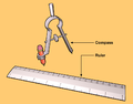 non collapsible compass and ruler

We set the origin Z to an arbitrary point. For Y, we are going down l and a to the left. The crank m can be at an arbitrary angle. Drawing the crank results in the point X.
From this point, we construct triangles that are defined by two points and two lengths.
In geometry, this is the SSS case (constructing a Triangle with three sides given, see also Solution of triangles#Three sides given (SSS)).
On paper, this can be easily solved using a compass.
Let us start with setting the compass to length b and then putting the compass in point Y. Then we set the compass to the length j and put the compass in point X. The crossing point of the arcs is the point W.
Note that when two points and two lengths are given, there are always two solutions, speak crossing points. Given that we already know the general shape of the mechanism, we know which one we need. But keep it mind for later.
The rest is more or less "rinse and repeat".
Geometric Construction Instructions
[edit | edit source]Conventions
[edit | edit source]- lengths are written in lower case
- point are written in upper case
- lines and arcs used for construction have a '
Instructions
[edit | edit source]- construct point Z
- draw a horizontal line h
- draw a vertical line v crossing the horizontal line h
- mark point Z where the h and v cross
- that will be the origin of this construction and crank axis of the leg mechanism
- construct point Y
- draw a horizontal line h' distance l down from h
- draw a vertical line v' distance a left from v
- label the crossing point of h' and v' as fix point Y
- construct point X
- draw a line m' trough Z add an arbitrary angle (the angle is the crank angle)
- draw an arc from point Z with radius m, the crossing point of arc n and Point Z is crank pivot X
- draw line m from Z to X
- construct point W (SSS case)
- draw an arc j' from point X with radius j
- draw an arc b' from point Y with radius b
- the crossing point of arc j' and b' is point W
- draw line j from X to W
- draw line b from Y to W
- construct point V (SSS case)
- draw an arc e' from point W with radius e
- draw an arc d' from point Y with radius d
- draw line e from W to V
- draw line d from Y to V
- the crossing point of arc e' and d' is point V
- construct point U (SSS case)
- draw an arc c' from point Y with radius c
- draw an arc k' from point X with radius k
- draw line c from Y to U
- draw line k from X to U
- the crossing point of arc c' and k' is point U
- construct point T (SSS case)
- draw an arc f' from point V with radius f
- draw an arc g' from point U with radius g
- the crossing point of arc f' and g' is point T
- draw line f from V to T
- draw line g from U to T
- construct point S (SSS case)
- draw an arc h' from point T with radius h
- draw an arc i' from point U with radius i
- the crossing point of arc f' and g' is point S
- this is the "foot" of the mechanism
- draw line h from T to S
- draw line i from U to S
-
 Step 1
 -
 Step 2
 -
 Step 3
 -
 Step 4
 -
 Step 5
 -
 Step 6
 -
 Step 7
 -
 Step 8


given lengths
[edit | edit source] a=38.0
b=41.5
c=39.3
d=40.1
e=55.8
f=39.4
g=36.7
h=65.7
i=49.0
j=50.0
k=61.9
l= 7.8
m=15.0
Points
[edit | edit source]Z fix point, origin, crank axis Y fix point X crank axis W V U T S foot

