Communication Systems/AM Receivers
AM Receivers
[edit | edit source]The most common receivers in use today are the super heterodyne type. They consist of:
- Antenna
- RF amplifier
- Local Oscillator and Mixer
- IF Section
- Detector and Amplifier
The need for these subsystems can be seen when one considers the much simpler and inadequate TRF or tuned radio frequency amplifier.
TRF Amplifier
[edit | edit source]It is possible to design an RF amplifier to accept only a narrow range of frequencies, such as one radio station on the AM band.
By adjusting the center frequency of the tuned circuit, all other input signals can be excluded.
The AM band ranges from about 500 kHz to 1600 kHz. Each station requires 10 kHz of this spectrum, although the baseband signal is only 5 kHz.
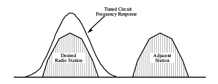
Recall that for a tuned circuit: . The center or resonant frequency in an RLC network is most often adjusted by varying the capacitor value. However, the Q remains approximately constant as the center frequency is adjusted. This suggests that as the bandwidth varies as the circuit is tuned.
- For example, the Q required at the lower end of the AM band to select only one radio station would be approximately:
- As the tuned circuit is adjusted to the higher end of the AM band, the resulting bandwidth is:
A bandwidth this high could conceivably pass three adjacent stations, thus making meaningful reception impossible.
To prevent this, the incoming RF signal is heterodyned to a fixed IF or intermediate frequency and passed through a constant bandwidth circuit.
Superheterodyne Receiver
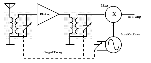
[edit | edit source]The RF amplifier boosts the RF signal into the mixer. It has broad tuning and amplifies not just one RF station, but many of them simultaneously. It also amplifies any input noise and even contributes some of its own.
The other mixer input is a high frequency sine wave created by a local oscillator. In AM receivers, it is always 455 kHz above the desired station carrier frequency. An ideal mixer will combine the incoming carrier with the local oscillator to create sum and difference frequencies. .
A real mixer combines two signals and creates a host of new frequencies:
- • A dc level
- • The original two frequencies
- • The sum and difference of the two input frequencies
- • Harmonics of the two input frequencies
- • Sums and differences of all of the harmonics
Since the RF amplifier passes several radio stations at once, the mixer output can be very complex. However, the only signal of real interest is the difference between the desired station carrier frequency and the local oscillator frequency. This difference frequency, also called the IF (intermediate frequency) will alway be 455 kHz. By passing this through a 10 kHz BPF (band pass filter) centered at 455 kHz, the bulk of the unwanted signals can be eliminated.
Local Oscillator Frequency
[edit | edit source]Since the mixer generates sum and difference frequencies, it is possible to generate the 455 kHz IF signal if the local oscillator is either above or below the IF. The inevitable question is which is preferable.
- Case I The local Oscillator is above the IF. This would require that the oscillator tune from (500 + 455) kHz to (1600 + 455) kHz or approximately 1 to 2 MHz. It is normally the capacitor in a tuned RLC circuit, which is varied to adjust the center frequency while the inductor is left fixed.
- Since
- solving for C we obtain
- When the tuning frequency is a maximum, the tuning capacitor is a minimum and vice versa. Since we know the range of frequencies to be created, we can deduce the range of capacitance required.
Making a capacitor with a 4:1 value change is well within the realm of possibility.
- Case II The local Oscillator is below the IF. This would require that the oscillator tune from (500 - 455) kHz to (1600 - 455) kHz or approximately 45 kHz to 1145 kHz, in which case:
It is not practical to make a tunable capacitor with this type of range. Therefore the local oscillator in a standard AM receiver is above the radio band.
Image Frequency
[edit | edit source]Just as there are two oscillator frequencies, which can create the same IF, two different station frequencies can create the IF. The undesired station frequency is known as the image frequency.
If any circuit in the radio front end exhibits non-linearities, there is a possibility that other combinations may create the intermediate frequency. Once the image frequency is in the mixer, there is no way to remove it since it is now heterodyned into the same IF band as the desired station.
AM Detection
[edit | edit source]There are two basic types of AM detection, coherent and non-coherent. Of these two, the non-coherent is the simpler method.
- Non-coherent detection does not rely on regenerating the carrier signal. The information or modulation envelope can be removed or detected by a diode followed by an audio filter.
- Coherent detection relies on regenerating the carrier and mixing it with the AM signal. This creates sum and difference frequencies. The difference frequency corresponds to the original modulation signal.
Both of these detection techniques have certain drawbacks. Consequently, most radio receivers use a combination of both.
Envelope Detector
[edit | edit source]An envelope detector is simply a half wave rectifier followed by a low pass filter. In the case of commercial AM radio receivers, the detector is placed after the IF section. The carrier at this point is 455 kHz while the maximum envelope frequency is only 5 kHz. Since the ripple component is nearly 100 times the frequency of the highest baseband signal and does not pass through any subsequent audio amplifiers.
- An AM signal where the carrier frequency is only 10 times the envelope frequency would have considerable ripple:
Synchronous Detector
[edit | edit source]In a synchronous or coherent detector, the incoming AM signal is mixed with the original carrier frequency.
If you think this looks suspiciously like a mixer, you are absolutely right! A synchronous detector is one where the difference frequency between the two inputs is zero Hz. Of in other words, the two input frequencies are the same. Let's check the math.
Recall that the AM input is mathematically defined by:
- At the multiplier output, we obtain:
- The high frequency component can be filtered off leaving only the original modulation signal.
- This technique has one serious drawback. The problem is how to create the exact carrier frequency. If the frequency is not exact, the entire baseband signal will be shifted by the difference. A shift of only 50 Hz will make the human voice unrecognizable. It is possible to use a PLL (phase locked loop), but making one tunable for the entire AM band is not trivial.
As a result, most radio receivers use an oscillator to create a fixed intermediate frequency. This is then followed by an envelope detector or a fixed frequency PLL.
Squaring Detector
[edit | edit source]The squaring detector is also a synchronous or coherent detector. It avoids the problem of having to recreate the carrier by simply squaring the input signal. It essentially uses the AM signal itself as a sort of wideband carrier.
- The output of the multiplier is the square of the input AM signal:
Since the input is being multiplied by the component, one of the resulting difference terms is the original modulation signal. The principle difficulty with this approach is trying to create a linear, high frequency multiplier.


