Circuit Theory/2Initially Excited


Charging
[edit | edit source]The source voltage could be DC. In this case the initial capacitor voltage is going to be Vs and the derivative of the voltage is going to be zero.
The source voltage could be AC in which case the exact time or more precise phase angle of the switch over is going to determine Vs and the derivative of the voltage values.
Discharging
[edit | edit source]The initial inductor current is going to be zero and derivative is going to be zero.
After a long time nothing will be going on. The steady state particular solution is going to be zero.
The current is going to be the same throughout. Goal should be to find an expression for the current. However, any voltage could also be found and then the current. Doesn't matter.
In summary, there will be no initial current in the discharging circuit, there will be a voltage across the capacitor. The inductor is going to act like an open at t=0+ so this entire voltage will appear across the inductor and instantly (between t=0- and t=0+) cause a change in the derivative of the current through the inductor.
The equation for the current for first order circuits would be:
However, this is a 2nd order circuit (with both capacitors and inductors), thus:
The complex frequency s has replace tau. The time constant concept disappears. An intuitive interpretation of s exists, but is more complicated. Remember:
The differential equation
[edit | edit source]Go back to the complex frequency domain to find the time constant. Start with the loop equation:
Substitute terminal equation for Vr and VL but not for Vc because want to avoid an integral:
From the terminal relation of a capacitor, know that:
So substituting in, have a differential equation for Vc:
Can see the second order now.
Finding the time constant or zeros
[edit | edit source]A zero is like a time constant, but there are more than one zero's possible. They might each influence the circuit differently.
Need to find Vc. The particular solution (steady state) is going to be zero. (Where the name zero comes from).
The homogeneous solution is going to be of this form:
Plugging into the differential equation:
Dividing out Aest have:
The zero's of this equation are:
From your experience with quadratics you know that 1,2 come in three types of pairs:
| Pair Type | Revised equation for Vc | interpretation |
|---|---|---|
| real, not equal | overdamped | |
| equal | critically damped | |
| complex | ) | underdamped |
The revised equations (guesses) come from math proofs, and some courses derive these from Laplace transformations. Just remember this table.
There are two storage elements with two initial conditions each, so there could be four equations and four constants. A1 and A2 are two of them.

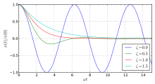
To understand damping, think of a car driving over a curb. Undamped means the car bounces up and down for ever. Under-damped is what happens when the shocks start leaking (car bounces up and down for a while ... like riding in a boat). Critically damped is why people hate sports cars (hurts their bottom). An over damped response in a car gives feedback to a person driving a car. Circuits like that above have been used to model shock obsorbers. These circuits are called analog computers.
Almost Resonance (Underdamped)
[edit | edit source]
The most interesting of the above three is Underdamped. Something like resonance occurs.
Satellites expand and contract depending upon which side is facing the sun or the 2.7 kelvin of space. Repeated expansion and contraction creates an oscillation that needs to be damped out by a motor that flings a weight around that dampens the vibration. Otherwise everything that can wiggle will wiggle more and more until parts begin to break off. (A car on earth is no different).
Most control circuit input is an unbalanced situation. The output models the desired behavior. The correcting (feedback control) circuits (not talked being studied here) kick in to make sure the actual behavior matches the desired behavior. Most often the objective is to design a critically damped circuit, rather than merely predict what is going to happen.
Resonance (or close to it) occurs when s1 and s2 are purely imaginary.
So:
What is interesting is the radical term. It determines the nature of the 2nd order response.
Pure resonance occurs when the real part of the quadratic solution is zero which would only happen when R << L.

The contents of the radical don't have to be zero, only the real part has to be zero in order to be overdamped:
The j's cancel, and we have already assumed R << L, so:
Which called the damped, ringing, or undamped frequency.
When R << L, then this turns into the resonate frequency:
Mechanical engineers try to predict ω for a given structure and materials. It could be a building or motor mount. The math proves that ω exists. Finding the exact ω usually requires testing. Instead of capacitors and inductors, mechanical engineers model everything with springs and dampers. Finding ω can be hard. This why there is an entire industry of shake tables.
The spring and damper values in a structure determine how narrow or muted the resonance is. When designing a building, mechanical engineers want the envelope to be as wide and flat (muted) as possible. When designing a notch filter the electrical engineer's design goal is the opposite: a tall and narrow envelope. Electrical engineers call this quality.
Most oscillators today are built from crystals.


