A-level Physics (Advancing Physics)/Motors

Just as a moving magnetic field induces current in conductors, a changing current in a magnetic field induces motion. When this motion is used to ensure that the current keeps changing relative to the magnetic field, the motion will continue, and so we have an electric motor. There are several types of electric motor.
Simple DC Motor
[edit | edit source]When a coil is placed inside a stationary magnetic field, and a direct current is run through the coil, the coil tries to align itself with the field since it becomes an electromagnet. This would be useless as a motor, since it would always move to the same position when you turned it on, and then stop. If, however, we use a split-ring commutator which changes the direction of the current every half-rotation, then the coil would try to align itself in the opposite direction every half-rotation. This means that, once the rotor starts to move, it continues to move. This is a DC electric motor. The permanent magnets can be replaced with electromagnets as well. The main advantage of this type of motor is that the commutator works, regardless of the frequency of rotation.

Three-phase Motor
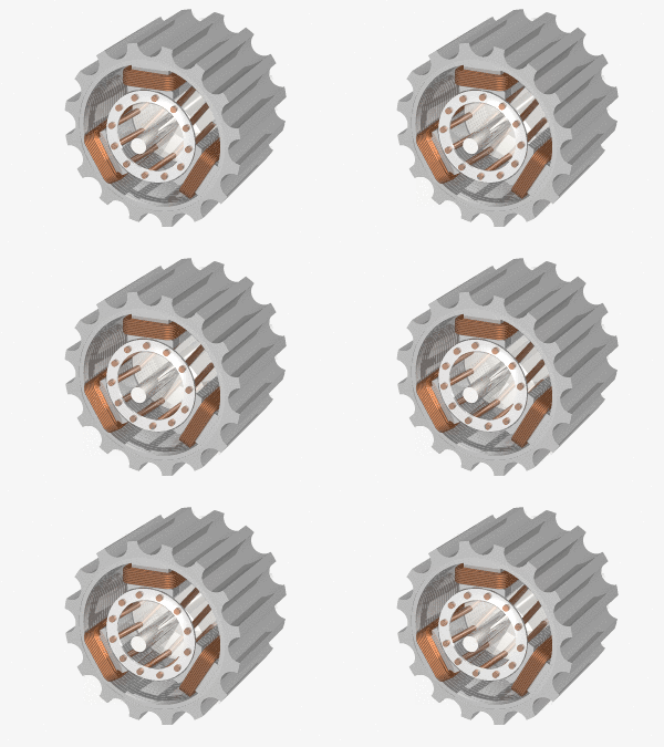
[edit | edit source]The three-phase power produced by a three-phase generator may be used to power a motor. Each phase of power is connected to one of three coils. This creates a magnetic field which rotates once for each cycle of the power. If a permanent magnet is placed in the middle, at any given time, its north pole will be attracted to a south pole in one of the coils, and will be repelled by a north pole in one of the coils. The converse would be true for its south pole. This means that the rotating magnetic field drags the magnet around with it, causing the magnet to rotate with the same frequency as the magnetic field. The disadvantage of this type of motor is that it goes at one frequency only - the frequency of the current.
The permanent magnet can be replaced with a coil with direct current in it. This creates a magnetic field, the advantage being that there is no need for a permanent magnet which is expensive and heavy. The main disadvantages are that electricity must be used to power the electromagnet, and that a slip-ring commutator must be used to prevent the coil getting tangled up and stopping the motor from running.

Squirrel Cage Motor
[edit | edit source]A squirrel cage motor works on a similar principle, except that the rotor is no longer a permanent magnet. Instead, a series of metal rods run through the rotor, connected to each other at either ends. The rods run perpendicular to the rotating magnetic field. Once the rotor starts to rotate, an electric current is created in the rods - eddy currents. This creates a magnetic field which is perpendicular to the rotating magnetic at all times. As the rotating magnetic field created by the stator rotates, it pulls the induced magnetic field around after it, causing the rotor to continue to rotate.
A squirrel cage motor relies on the fact that the two magnetic fields are rotating at different rates. If they were not, then there would be no change in flux in the rotor, and so no eddy currents would be induced.
Questions
[edit | edit source]1. How could you adapt the simple DC motor to use AC?
2. Why does a three-phase motor have a constant angular velocity?
3. What is the difference between a split-ring and a slip-ring commutator?
4. How could the angular velocity of a three-phase motor be increased?
5. A squirrel-cage motor relies on eddy currents running along the rotor to function. However, if eddy currents run across the rotor, then the force on the rotor is reduced. How may these eddy currents be reduced without reducing the desired eddy currents?
