Descriptive Geometry/Introduction
Descriptive geometry is a branch of mathematics used to transform three-dimensional objects into two-dimensional representations that can then be presented on paper, computer screens, or some similar medium. Its principles are valuable for determining true shapes of planes, angles between lines, and locating intersection between line and planes. Problems are solved graphically by projecting points onto selected adjacent projection planes in an imaginary projection system. The techniques explained in this text are applicable to various architecture, art, design, and engineering activities, such as perspective drawing and drafting.
Table of Contents:
1: Picture Plane
2: Views
3: Transfer Distances
4: Plans/Elevations
5: Auxiliary Views
6:Point/Lines/Planes/Solid

Picture Plane:
Planes are the most fundamental and most common found in the field of descriptive geometry. A plane is defined as a flat surface that could be represented by three points that are not in a straight line, a straight line and a point not of the line, two intersecting lines, and two parallel lines. The picture plane, or plane of projection, is the surface on which an object is projected, and any plane parallel to either the top or front plane can be used as the picture plane, but for simplicity of construction, the top or front planes will be used as the picture planes.
Other categorization of planes include inclined plane and oblique planes, which may appear as any shape, but one can find the true shape of a plane through a series of plane projections. An inclined plane is defined as a plane that appears as a line in at least one of the standard views of projection (top, front), and foreshortened in the other views. The true shape of the inclined plane can be found in a first auxiliary view. When a plane does not appear as a line (edge) in any of the standard views, it is considered an oblique plane, and the true shape of the plane can be found only in a secondary auxiliary view.

Views:
A view is a 2D infinite surface, called the picture plane, upon which 3D objects are projected onto. Projections, achieved with projection lines that lie perpendicular to the picture plane, map each point on an object to the corresponding point on the image of that object. Because the lines are always perpendicular we call such projections orthographic projections. Views are the stepping block to learning descriptive geometry – with the use of projection lines in views, we are able to complete plan views and elevation views of any geometric figure, and are able to construct the shades and shadows cast by objects. Projections have two important properties: uniqueness and between-ness.
• Uniqueness is best described with two non-parallel lines, say a and b, one of which contains a point, say C; and a family of parallel lines. The property says that there will be a line that’s part of the family of parallel lines that goes through point C on line a, and will project point C’ where it crosses line b. C is the figure, and C’ is the image.
• Between-ness means that distances stay the same throughout projections. Say we have a straight line a and a curved line b. Even though b is technically longer in length, the endpoints of both lines will line up, with perpendicular lines joining them. The same is true for any point in between the endpoints. Parallel projections apply lot only to points and lines, but also planes and figures. They are constructed with the same projection lines and also share properties of uniqueness and between-ness. It is important to note, however, that distances will be preserved only when the lines, or planes, on which the objects lie are in fact parallel. Where one view ends and another begins is the line called folding line. Folding lines help us indicate transfer distances.
-
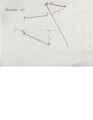
 Concept - Views Number 1
 -
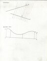 Concept - Views Number 2
 -
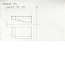 Problem Number Two - Views
 -
 Solution Number Two - Views


Transfer Distance:
In Descriptive Geometry, transfer distances are crucial elements that help create the different views of an object. The process of transferring various points on the object into a different view is called projection. Projection helps in the understanding of the object as a three dimensional form. Generally, for orthogonal or angular shapes the points that are transferred are the intersections and corners of the object. On curved shapes, the transfer points lie on the curve equidistant from one another. The first step in projecting an object into a different view is to extend lines from the chosen points on the object in the second view. These lines must be perpendicular to the folding line. In the first view, measure the distance from each chosen point to that folding line. These measurements are the transfer distances that will create the projection in the third view. Extend the perpendicular line of the chosen points to the length of the transfer distances. Once all the points are projected into the third view, connect the points to get the object in that view.
Example Problem 1: http://commons.wikimedia.org/wiki/File:Projections_Problem_1.pdf
Example Problem 1 Solution: http://commons.wikimedia.org/wiki/File:Projections_Problem_1_SOLUTION.pdf
Example Problem 2:
http://commons.wikimedia.org/wiki/File:Projections_Problem_2.pdf
Example Problem 2 Solution: http://commons.wikimedia.org/wiki/File:Projections_Problem_2_Solution.pdf
Plans/Elevations:
Plans and elevation some of the primary reasons descriptive geometry comes into play with architecture. Plan and elevation views can also be defined as projections on the horizontal and vertical planes respectively. To construct a building plan, you just create a picture plane in the top view that slices the building just below the roof. Similarly, elevation is an architecture drawing taken in the front view. Other views like section cuts can be also obtained by using a front view that cuts through the building.
Plan, elevation, and section views are categorized as orthographic views, which means they do not contain any foreshortening due to perspective. However non-orthographic lines such as slant or diagonal walls will be foreshortened. These views can also be utilized in construction, and alternate elevations can also be obtained through auxiliary views. Constructions will be discussed in later chapters.
Auxiliary Views:

Auxiliary views are specific kind of views that allow us to see plans or elevations more clearly, receive additional information of the sides of objects, and get the true lengths and shapes of objects. These views are drawn as picture planes that are perpendicular to the primary views, plans or elevations. We are allowed to take as many auxiliary views as we wish, granted they are all perpendicular to one another or the primary views. Note that the secondary views could be on an incline yet still be perpendicular to a plan view or an elevation view.
-
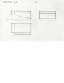
 Problem Number One - Auxiliary View
 -
 Solution Number One - Auxiliary View


Terms:


Point- determined by a coordinate in the horizontal x-axis, the vertical y-axis, and depth z-axis. A point has no dimension because it does not have length, area or volume.
Line- an infinite number of points that connect two given points. A line is one-dimensional because it has no width or depth.

Plane- a two-dimensional surface with all its points and lines on either the x, y or z axis
Solid-a three-dimensional object that includes length, area and volume.
reference:
Ingrid Carlbom, Joseph Paciorek (December 1978), "Planar Geometric Projections and Viewing Transformations", ACM Computing Surveys 10 (4): 465–502
Leslie A. Lee, Ronald Fraser Reekie (May, 22, 2007),"Descriptive Geometry for Architects and Builders", University of Wisconsin - Madison
Frederick Newton Willson (April 2011),"Descriptive Geometry--Pure and Applied", MacMillan