Basic Physics of Nuclear Medicine/Scintillation Detectors

The second type of radiation detector we will discuss is called the scintillation detector. Scintillations are minute flashes of light which are produced by certain materials when they absorb radiation. These materials are variously called fluorescent materials, fluors, scintillators or phosphors.
If we had a radioactive source and a scintillator in the lab we could darken the room, move the scintillator close to the source and see the scintillations. These small flashes of light might be green or blue or some other colour depending on the scintillator. We could also count the number of flashes produced to gain an estimate of the radioactivity of the source, that is the more flashes of light seen the more radiation present.
The scintillation detector was possibly the first radiation detector discovered. You might have heard the story of the discovery of X-rays by Wilhelm Roentgen in 1895. He was working one evening in his laboratory in Wurzburg, Germany with a device which fired a beam of electrons at a target inside an evacuated glass tube. While working with this device he noticed that some platino-barium cyanide crystals, which he just happened to have close by, began to glow – and that they stopped glowing when he switched the device off. Roentgen had accidentally discovered a new form of radiation. He had also accidentally discovered a scintillator detector.
Although scintillations can be seen we have a more sophisticated way of counting and measuring them today by using some form of photodetector.
We will learn about the construction and mode of operation of this type of detector in this chapter. In addition, we will see how it can be used not just for detecting the presence of ionizing radiation but also for measuring the energy of that radiation.
Before we do however it is useful to note that scintillators are very widely used in the medical radiations field. For example the X-ray cassette used in radiography contains a scintillator (called an intensifying screen) in close contact with a photographic film. A second example is the X-ray Image Intensifier used in fluoroscopy which contains scintillators called phosphors. Scintillators are also used in some CT Scanners and as we will see in the next chapter, in the Gamma Camera and PET Scanner. Their application is not limited to the medical radiations field in that scintillators are also used as screens in television sets and computer monitors and for generating light in fluorescent tubes – to mention just two common applications. What other applications can you think of?
So scintillators are a lot more common than you might initially think and you will therefore find the information presented here useful to you not just for your studies of nuclear medicine.
Fluorescent Materials[edit | edit source]
Some fluorescent materials are listed in the following table. Thallium-activated sodium iodide, NaI(Tl) is a crystalline material which is widely used for the detection of gamma-rays in scintillation detectors. We will be looking at this in more detail below.
Another crystalline material sodium-activated caesium iodide, CsI(Na) is widely used for X-ray detection in devices such as the X-ray image intensifier. Another one called calcium tungstate, CaWO4 has been widely used in X-ray cassettes although this substance has been replaced by other scintillators such as lanthanum oxybromide in many modern cassettes.
| Material | Form |
|---|---|
| NaI (Tl) | crystal |
| CsI (Na) | crystal |
| CaWO4 | crystal |
| ZnS (Ag) | powder |
| p-terphenyl in toluene | liquid |
| p-terphenyl in polystyrene | plastic |
Notice that some scintillation materials are activated with certain elements. What this means is that the base material has a small amount of the activation element present. The term doped is sometimes used instead of activated. This activating element is used to influence the wavelength (colour) of the light produced by the scintillator.
Silver-activated zinc sulphide is a scintillator in powder form and p-terphenyl in toluene is a liquid scintillator. The advantage of such forms of scintillators is that the radioactive material can be placed in close contact with the scintillating material. For example if a radioactive sample happened to be in liquid form we could mix it with a liquid scintillator so as to optimise the chances of detection of the emitted radiation and hence have a very sensitive detector.
A final example is p-terphenyl in polystyrene which is a scintillator in the form of a plastic. This form can be easily made into different shapes like most plastics and is therefore useful when detectors of particular shapes are required.
Photomultiplier Tube[edit | edit source]
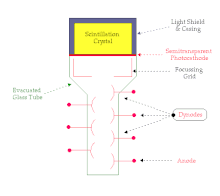
A scintillation crystal coupled to a photomultiplier tube (PMT) is illustrated in the following figure. The overall device is typically cylindrical in shape and the figure shows a cross-section through this cylinder:

The scintillation crystal, NaI(Tl) is very delicate and this is one of the reasons it is housed in an aluminium casing. The inside wall of the casing is designed so that any light which strikes it is reflected downwards towards the PMT.
The PMT itself consists of a photocathode, a focussing grid, an array of dynodes and an anode housed in an evacuated glass tube. The function of the photocathode is to convert the light flashes produced by radiation attenuation in the scintillation crystal into electrons. The grid focuses these electrons onto the first dynode and the dynode array is used for electron multiplication. We will consider this process in more detail below. Finally the anode collects the electrons produced by the array of dynodes.
The electrical circuitry which is typically attached to a PMT is shown in the next figure:

It consists of a high voltage supply, a resistor divider chain and a load resistor, RL. The high voltage supply generates a dc voltage, Vdc which can be up to 1,000 volts. It is applied to the resistor divider chain which consists of an array of resistors, each of which has the same resistance, R. The function of this chain of resistors is to divide up Vdc into equal voltages which are supplied to the dynodes. As a result voltages which increase in equal steps are applied to the array of dynodes. The load resistor is used so that an output voltage, Vout can be generated.
Finally the operation of the device is illustrated in the figure below:

The ionizing radiation produces flashes of light in the scintillation crystal. This light strikes the photocathode and is converted into electrons. The electrons are directed by the grid onto the first dynode.
Dynodes are made from certain alloys which emit electrons when their surface is struck by electrons with the advantage that more electrons are emitted than are absorbed. A dynode used in a PMT typically emits between two and five electrons for each electron which strikes it.
So when an electron from the photocathode strikes the first dynode between two and five electrons are emitted and are directed towards the second dynode in the array (three are illustrated in the figure). This electron multiplication process is repeated at the second dynode so that we end up with nine electrons for example heading towards the third dynode. An electron avalanche therefore develops so that a sizeable number of electrons eventually hits the anode at the bottom of the dynode chain.
These electrons flow through the load resistor, RL and constitute an electric current which according to Ohm's Law generates a voltage, Vout which is measured by electronic circuitry (which we will describe later).
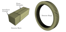
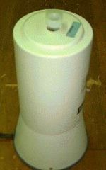
A number of photographs of devices based on scintillation detection are shown below:
The important feature of the scintillation detector is that this output voltage, Vout is directly proportional to the energy deposited by the radiation in the crystal. We will see what a useful feature this is below. Before we do so we will briefly analyze the operation of this device.
Mathematical Model[edit | edit source]
A simple mathematical model will be presented below which will help us get a better handle on the performance of a scintillation detector. We will do this by quantifying the performance of the scintillator, the photocathode and the dynodes.
Let's use the following symbols to characterize each stage of the detection process:
- m: number of light photons produced in crystal
- k: optical efficiency of the crystal, that is the efficiency with which the crystal transmits light
- l: quantum efficiency of the photocathode, that is the efficiency with which the photocathode converts light photons to electrons
- n: number of dynodes
- R: dynode multiplication factor, that is the number of secondary electrons emitted by a dynode per primary electron absorbed.
Therefore the charge collected at the anode is given by the following equation:
where e: the electronic charge.
For example supposing a 100 keV gamma-ray is absorbed in the crystal. The number of light photons produced, m, might be about 1,000 for a typical scintillation crystal. A typical crystal might have an optical efficiency, k, of 0.5 – in other words 50% of the light produced reaches the photocathode which might have a quantum efficiency of 0.15. A typical PMT has ten dynodes and let us assume that the dynode multiplication factor is 4.5.
Therefore
This amount of charge is very small. Even though we have used a sophisticated photodetector like a PMT we still end up with quite a small electrical signal.
A very sensitive amplifier is therefore needed to amplify this signal. This type of amplifier is generally called a pre-amplifier and we will refer to it again later.
Output Voltage[edit | edit source]
We noted above that the voltage measured across the resistor, RL, is proportional to the energy deposited in the scintillation crystal by the radiation. Let us consider how the radiation might deposit its energy in the crystal.
Let us consider a situation where gamma-rays are detected by the crystal. We learnt in Chapter 5 that there were two interaction mechanisms involved in gamma-ray attenuation – the Photoelectric Effect and the Compton Effect. You will remember that the Photoelectric Effect involves the total absorption of the energy of a gamma-ray, while the Compton Effect involves just partial absorption of this energy. Since the output voltage of a scintillation detector is proportional to the energy deposited by the gamma-rays it is reasonable to expect that Photoelectric Effects in the crystal will generate distinct and relatively large output voltages and that Compton Effects will result in lower output voltages.
The usual way of presenting this information is by plotting a graph of the count rate versus the output voltage pulse height as shown in the following figure:

This plot illustrates what is obtained for a monoenergetic gamma-emitting radioisotope, for example 99mTc – which, as we have noted before emits a single gamma-ray with an energy of 140 keV.
Before we look at it in detail remember that we noted above that the output voltage from this detector is proportional to the energy deposited by the radiation in the crystal. The horizontal axis can therefore be used to represent the output voltage or the gamma-ray energy. Both of these quantities are shown in the figure to help with this discussion. In addition note that this plot is often called a Gamma-Ray Energy Spectrum.
The figure above contains two regions. One called the Photopeak and the other called the Compton Smear. The Photopeak results because of Photoelectric absorption of the gamma-rays from the radioactive source – remember that we are dealing with a monoenergetic emitter in this example. It consists of a peak representing the gamma-ray energy (140 keV in our example). If our radioisotope emitted gamma-rays of two energies we would have two photopeaks in our spectrum and so on.
Notice that the peak has a statistical spread. This has to do with how good our detector is and we will not get into any detail about it here other than to note that the extent of this spread is a measure of the quality of our detector. A high quality (and more expensive!) detector will have a narrower statistical spread in the photopeaks which it measures.
The other component of our spectrum is the Compton Smear. It represents a range of output voltages which are lower than that for the Photopeak. It is therefore indicative of the partial absorption of the energy of gamma-rays in the crystal. In some Compton Effects a substantial scattering with a valence electron can occur which gives rise to relatively large voltage pulses. In other Compton Effects the gamma-ray just grazes off a valence electron with minimal energy transfer and hence a relatively small voltage pulse is generated. In between these two extremes are a range of scattering events involving a range of energy transfers and hence a range of voltage pulse heights. A 'smear' therefore manifests itself on the gamma-ray energy spectrum.
It is important to note that the spectrum illustrated in the figure is simplified for the sake of this introductory discussion and that actual spectra are a little more complex – see figure below for an example:

You will find though that your understanding of actual spectra can easily develop on the basis of the simple picture we have painted here.
It is also important to appreciate the additional information which this type of radiation detector provides relative to a gas-filled detector. In essence gas-filled detectors can be used to tell us if any radiation is present as well as the amount of that radiation. Scintillation detectors also give us this information but they tell us about the energy of this radiation as well. This additional information can be used for many diverse applications such as the identification of unknown radioisotopes and the production of nuclear medicine images. Let us stay a little bit longer though with the fundamental features of how scintillation detectors work.
The photopeak of the Gamma-Ray Energy Spectrum is generally of interest in nuclear medicine. This peak is the main signature of the radioisotope being used and its isolation from the Compton Smear is normally achieved using a technique called Pulse Height Analysis.
Pulse Height Analysis[edit | edit source]
This is an electronic technique which allows a spectrum to be acquired using two types of circuitry. One circuit is called a Lower Level Discriminator which only allows voltages pulses through it which are higher than its setting. The other is called an Upper Level Discriminator which only allows voltage pulses though which are lower than its setting.
The result of using both these circuits in combination is a variable-width window which can be placed anywhere along a spectrum. For example if we wished to obtain information from the photopeak only of our simplified spectrum we would place the discrimination controls as shown in the following figure:

A final point to note here is that since the scintillation detector is widely used to obtain information about the energies of the radiation emitted from a radioactive source it is frequently referred to as a Scintillation Spectrometer.
Scintillation Spectrometer[edit | edit source]
Types of scintillation spectrometer fall into two basic categories – the relatively straight-forward Single Channel Analyser and the more sophisticated Multi-Channel Analyser.
The Single Channel Analyser is the type of instrument we have been describing so far in this discussion. A block diagram of the instrument is shown below:

It consists of a scintillation crystal coupled to a photomultiplier tube which is powered by a high voltage circuit (H.V.). The output voltages are initially amplified by a sensitive pre-amplifier (Pre-Amp) as we noted above before being amplified further and conditioned by the amplifier (Amp).
The voltage pulses are then in a suitable form for the pulse height analyser (P.H.A.) – the output pulses from which can be fed to a Scaler and a Ratemeter for display of the information about the portion of the spectrum we have allowed to pass through the PHA. The Ratemeter is a display device just like the speedometer in a car and indicates the number of pulses generated per unit time. The Scaler on the other hand usually consists of a digital display which shows the number of voltage pulses produced in a specified period of time.
We can illustrate the operation of this circuitry by considering how it might be used to generate a Gamma-Ray Energy Spectrum. What we would do is set up the LLD and ULD so as to define a narrow window and place this to pass the lowest voltage pulses produced by the detector through to the Scaler and Ratemeter. In other words we would place a narrow window at the extreme left of the spectrum and acquire information about the lowest energy gamma-ray interactions in the crystal. We would then adjust the LLD and ULD settings to acquire information about the interactions of the next highest energy. We would proceed in this fashion to scan the whole spectrum.
A more sophisticated detector circuit is illustrated in the following figure:

It is quite similar to that in the previous figure with the exception that the PHA, Scaler and Ratemeter are replaced by a Multi-Channel Analyser and a computer. The Multi-Channel Analyser (MCA) is a circuit which is capable of setting up a large number of individual windows to look at a complete spectrum in one go. The MCA might consist of 1024 individual windows for example and the computer might consist of a personal computer which can acquire information simultaneously from each window and display it as an energy spectrum. The computer generally contains software which allows us to manipulate the resultant information in a variety of ways. Indeed the 137Cs spectrum shown above was generated using this approach.


